

Home of K-fab

|
|
|
|
The Mini-Raptor Build, 2020
2016 build
2017 build
2018 build
2019 build
2020 build
2021 build
2022 build
2023 build
Jan 11, 2020
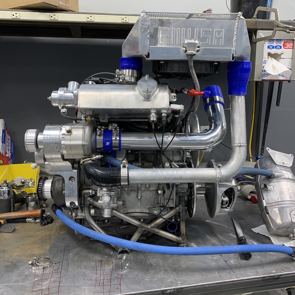
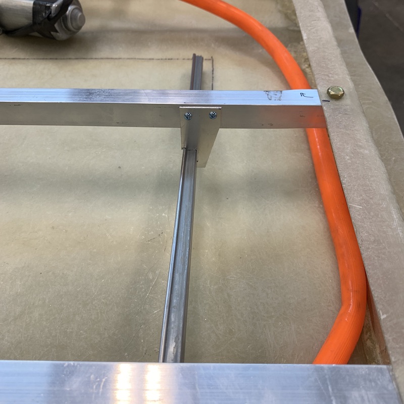
I've been needing to make a small diameter tubing bender for a long time now. While the power plant sits on my bench the tubing holding the intercooler in place has one piece that has to go around the fuel line, dodges another tube and kinda snakes through its area.
Problem was that the first attempt looked like something some crackhead made with a hammer and crescent wrench. It's bothered me since I made it so it was time for a bender.
Turned out pretty well - and I have room for a 5/8" or 3/4" addition.
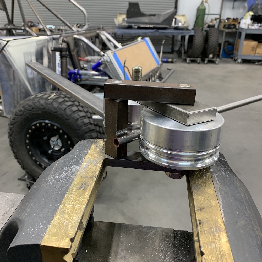
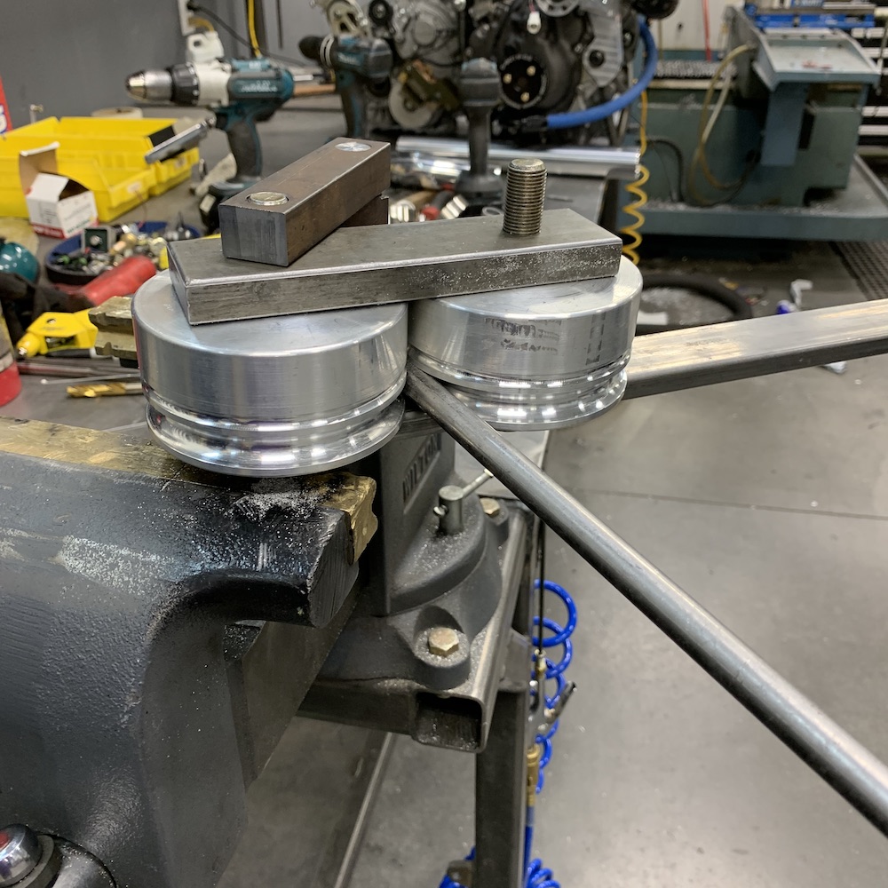
The result was much better - no mo crackhead and now has swoop.
Of course, as I lowered the power plant into the chassis today I discover that the clearance is wrong and hits two spots on the fuel pressure regulator. Shit...
So I've hacked off the leg, bent a new one up and it's presently hanging in place, waiting to be massaged a tad more then welded in place. Pix later.
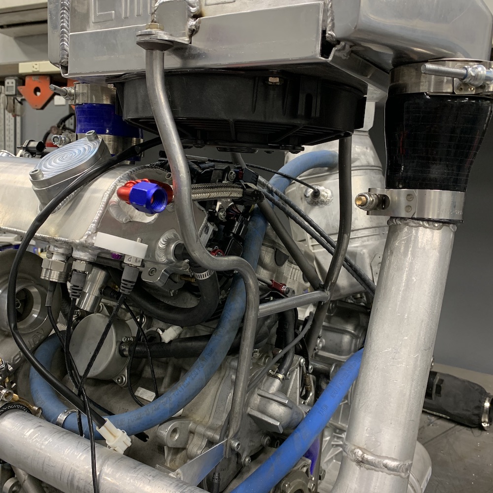
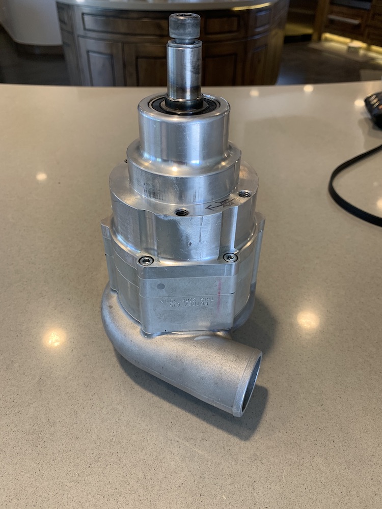
I also got around to moving the thermostat housing. Found the OEM one and started hacking away. Took the top incoming tube and moved it from the side to the top, cut off the bypass tube and blocked it off and machined a few bosses and bungs off of the piece. It fits nicely behind the pressure line from the supercharger.

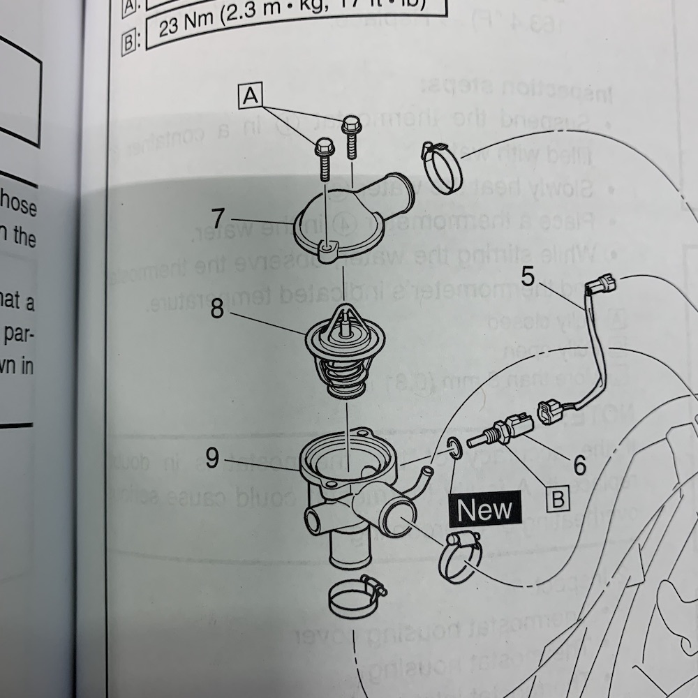
Here's a shot of the thermostat in the manual to see what I removed/moved.
Test fitment - it actually is about 3 or so inches higher and angles towards the center of the engine.
Jan 19, 2020
ADHD at work. I've been bouncing among a few aspects whilst waiting on stuff.
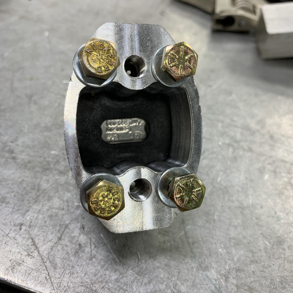
Have had a set of Flea-bay calipers sitting in a box for a while. They were very dirty and needed some attention. The oversized rotor mounts also needed some modifying (weight removal is what I'm calling it).
First thing was to get rid of all the casting lines. Little crap like that seems unfinished/unrefined. A little elbow work with some sanding and scotchbrite discs and then a trip through the bead blaster and I have shiny new brake clampers.
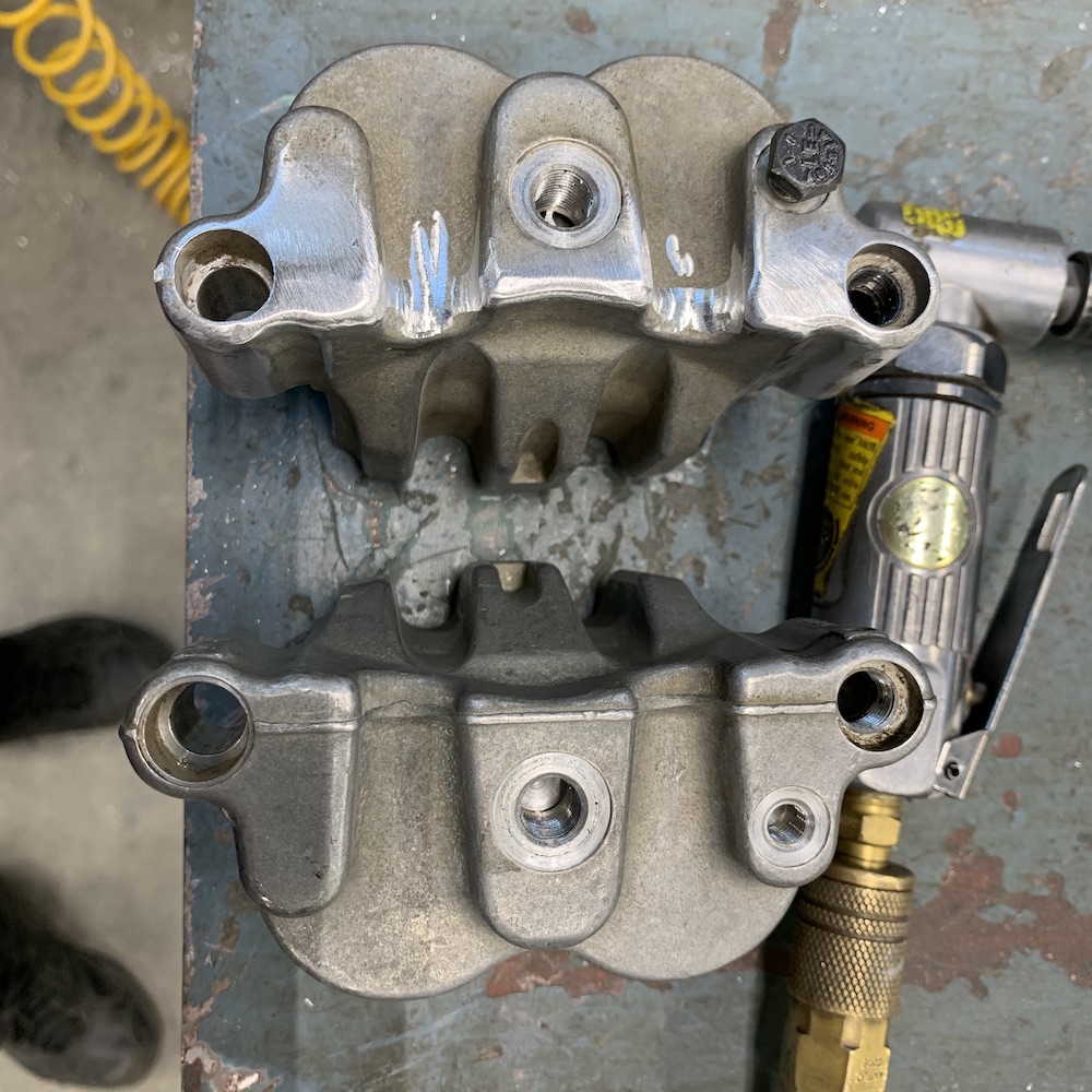
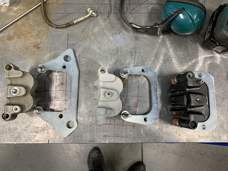
Left to right:
Dirty caliper, kit supplied oversized rotor mount.
Blasted caliper, weight relieved mount.
Painted, assembled, ready to install caliper and mount
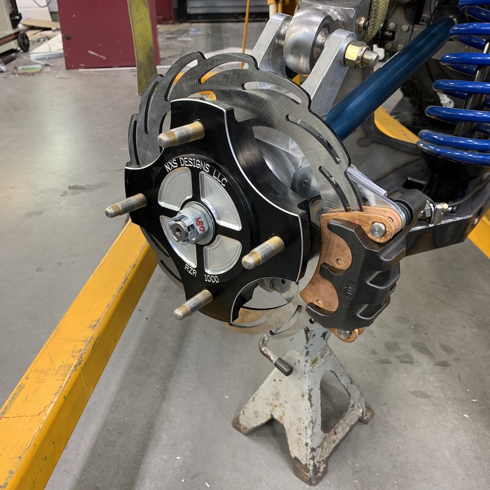
Left front installed and ready for fluid.
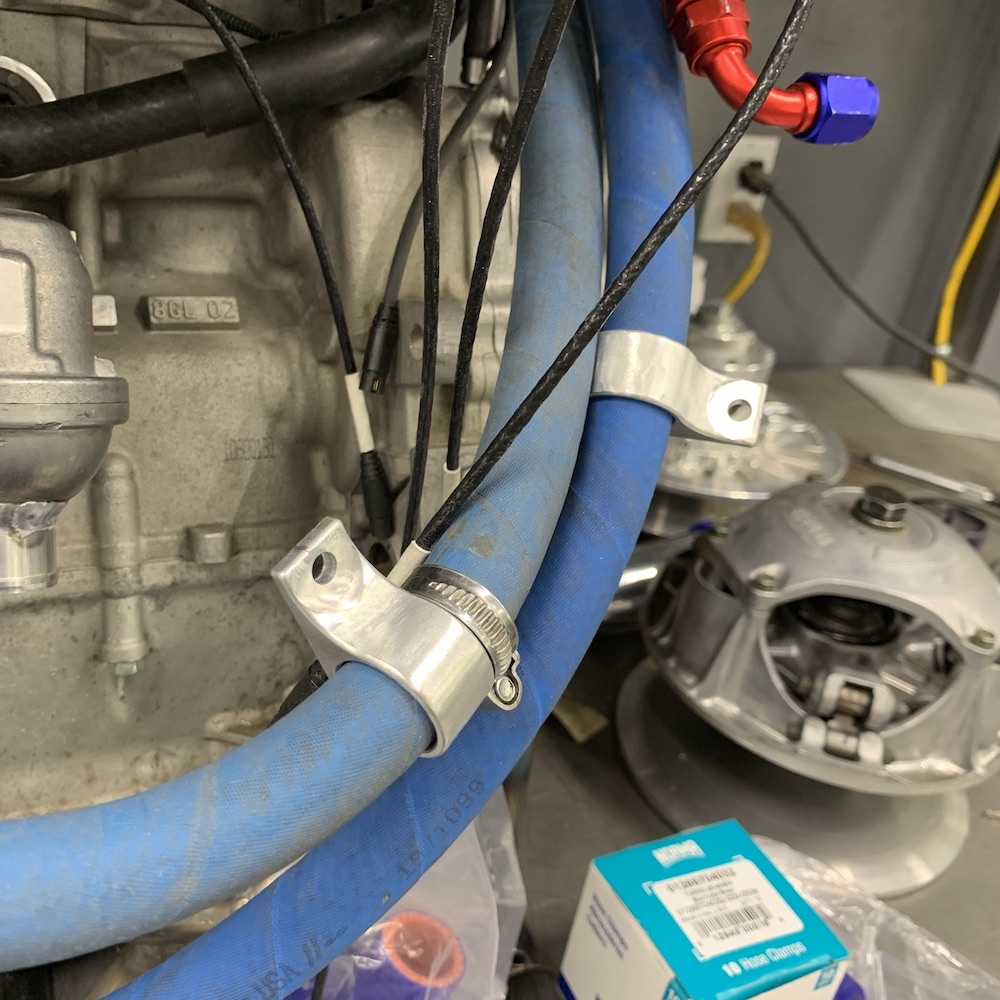
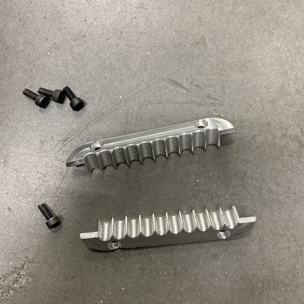
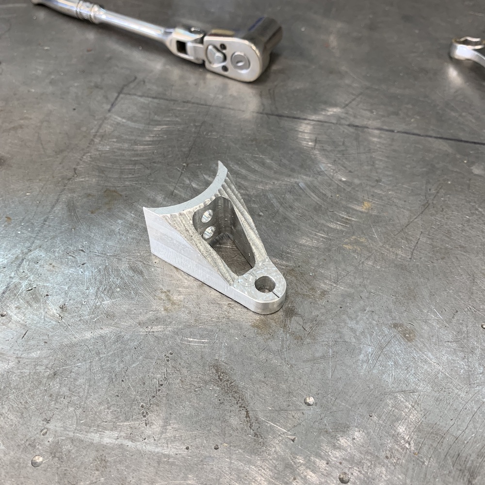
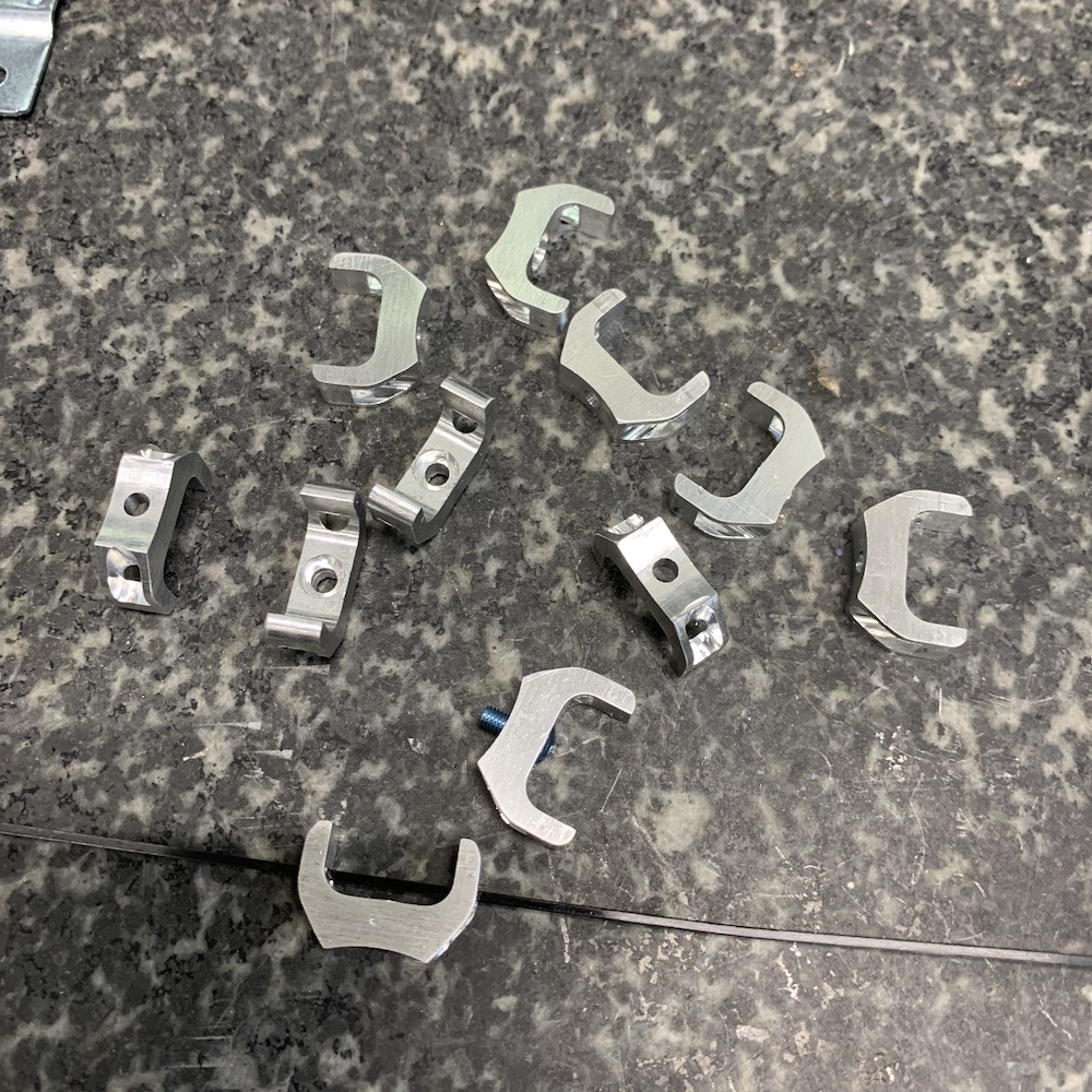
Also knocked out a couple of hose mounts. These will keep the lines between the oil tank and the engine tucked against the firewall and out of the way of stuff:
-------
(heck I'm gonna copy my FB post - being lazy and don't feel like typing a bunch:)
Supercharger is on the way to repair - when I filled it with lube a few weeks ago I ended up with blue oil in the pressure tube.
Shit.
What sucks is that MPI (who makes the SC conversation) rebuilt it a year or so ago. It would appear they dorked a seal when they put it back together.
It's the busy season and I can't get an answered call.Internet search finds a place that rebuilds superchargers and sells seals.
So I decided I'd give it a shot and see if I could break into the Rotrex C-15 charger and replace the seal(s) myself. Heck, it's broken so why not see if I can fix it first.
Nope! Okay, now I have a leaky SC with a loose impeller. Off it went for repair. Its supposed to be on vacation from my place for 2-3 weeks according to the repair place. Supercharger Spa - comes back all shiny, clean, not leaking, ready for action.
-------------v
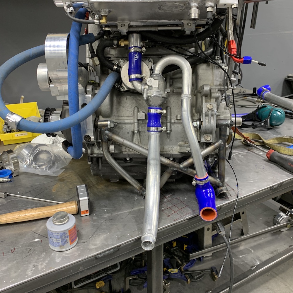
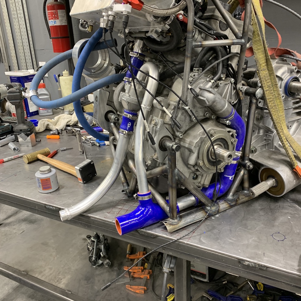
Got a box with tubing a couple of days ago so I got to finish up the thermostat circuit last night.
At least it's three steps forward and only one back now, sort of...
Third time's a charm...
The Thermostat Saga comes to an end (except for the missing bleed nipple on the u bend).
Started out with the thermostat up front in the radiator and no OEM bypass circuit. I took some bad advice and fortunately some (good?) bad luck reared its ugly head and the thermostat ends up getting put back on the engine end of the cooling system.
Then let's say there were a series of errors and observations that even managed to trip up our local Wizard.
Phone calls were made.
Internet pictures were studied.
Realizations came to surface.
The damn thing is now plumbed correctly, the bypass circuit is back in place and the cooling system is now done.
Another box checked off the list.
Front shock rebuild next on the list. One had some issues that I tended to but needed some parts. Have them now. The other one needs oil and a nitrogen charge. They shouldn't take long (and now that I've said that it's going to be an oil covered, long day at the work bench).
Jan 20, 2020
Worked on sealing the thermostat assembly today.
Already had some aluminium plugs that fit the silicone coupler tubing well, made a stepped stopper with an air chuck valve - you know, professional like.
All pieces band clamped, ready for pressure.
Add air.
Dunk in water.
Find leaks, remove from bucket.
Pull schrader valve so no pressure is built from the welding heat (it blows the weld out), weld leaks, plug, repeat.
Chased them for at least an hr.
Blew stepped stopper off once - chuck got caught.
Pop.
System is good for 100 psi, not 120.
Final leak check shows all is good.
I set it down and muck with something else for a moment.
Decide to put it back on the engine.
Hold it up in front of me so I can remove the plugs.
Put Makita drill with socket on band clamp to remove plug.
Pulled Makita trigger.
POP!
Had forgotten about pressure.
Plug nailed me in the right nut, perfectly.
Glad the bench was so nice and held me whilst I took deep breaths.
Wish I had it on video. AFV worthy.
Jan 27, 2020
Assembly to run continues.
Holy crap there's a lot of stuff in here.
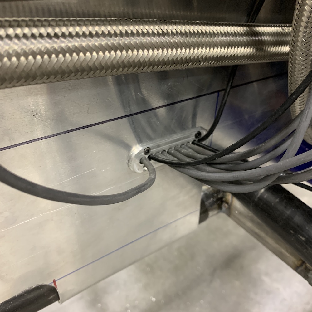
Realized that the wires for the AiM system needed to come through the firewall safely so I knocked out a little billet piece for safe passage:
I also got the 1/2" (12mm) heater core feeder line installed in the coolant transfer tube assembly:
One thing that I'd not addressed yet was the high mount brake light. Have been tossing around ideas of where to mount it. Originally I thought under the rear lip of the roof but that puts it in the middle of the top of the rear glass and there's no really good way to mount it to the cross bar.
I always thought it would look good in the stock place like you see on full sized trucks - upper edge of the back of the roof. Wasn't sure I had clearance between the roof and cage, though. Did some measuring and sure enough I had room so I got brave, pulled out the cutting and filing tools and a Sharpie.
Game on - had one chance to get it correct.
I got it correct! WHEW. 3.5 hours from start to finish.
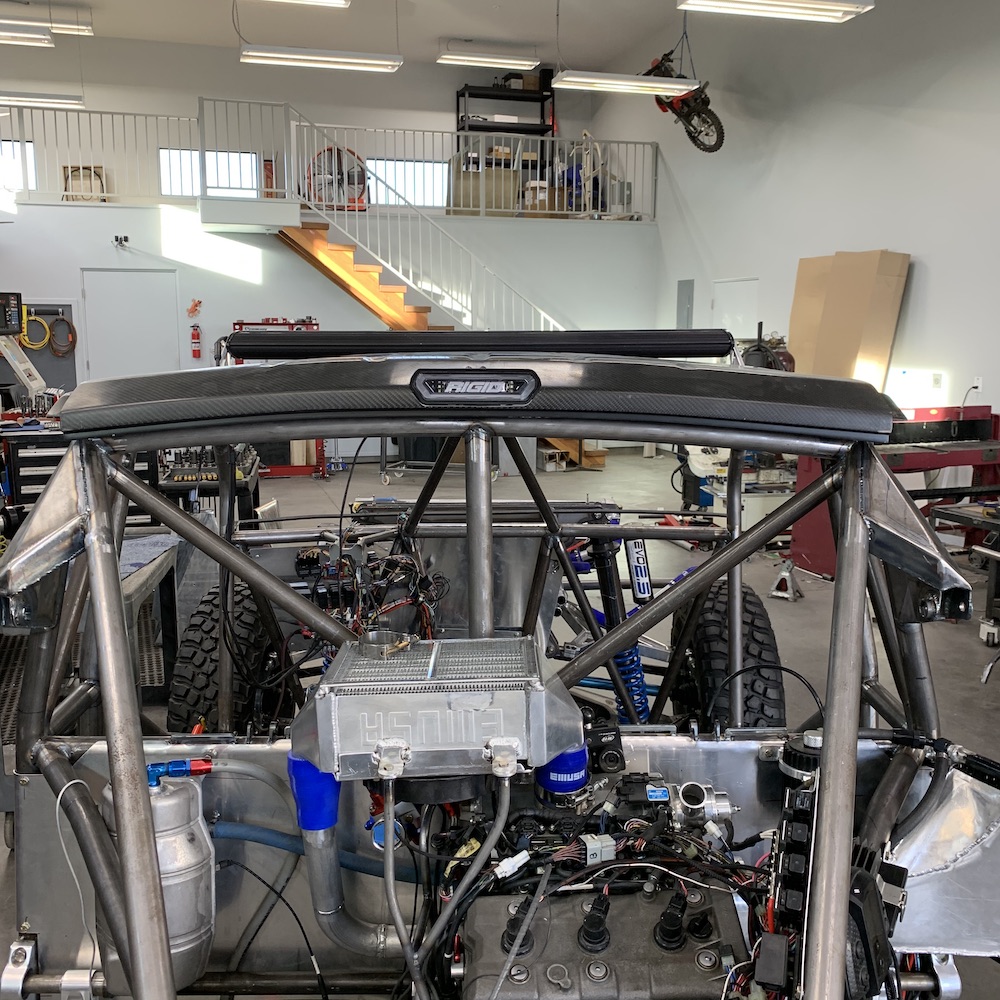
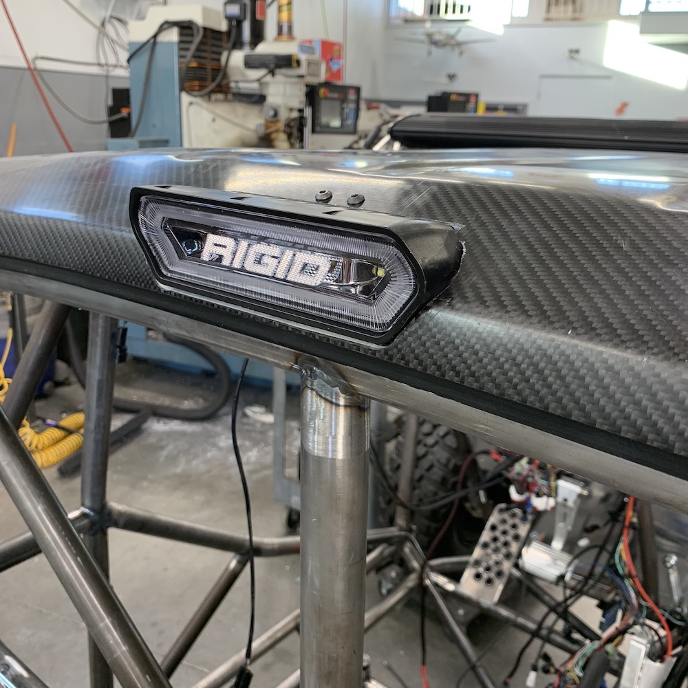
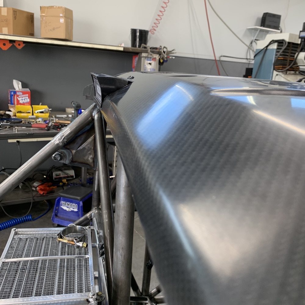
Started out by sinking it horizontally into the back of the roof and then opening up the hole in the top part of the roof until the light sunk in flush to the bottom of the roof.
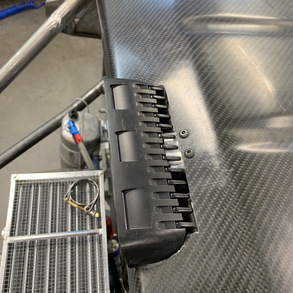
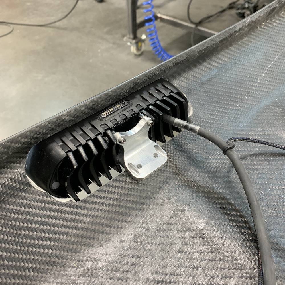
Once I got the light in place I made a quick mount to secure it in its home and the thing darned near clips into position.
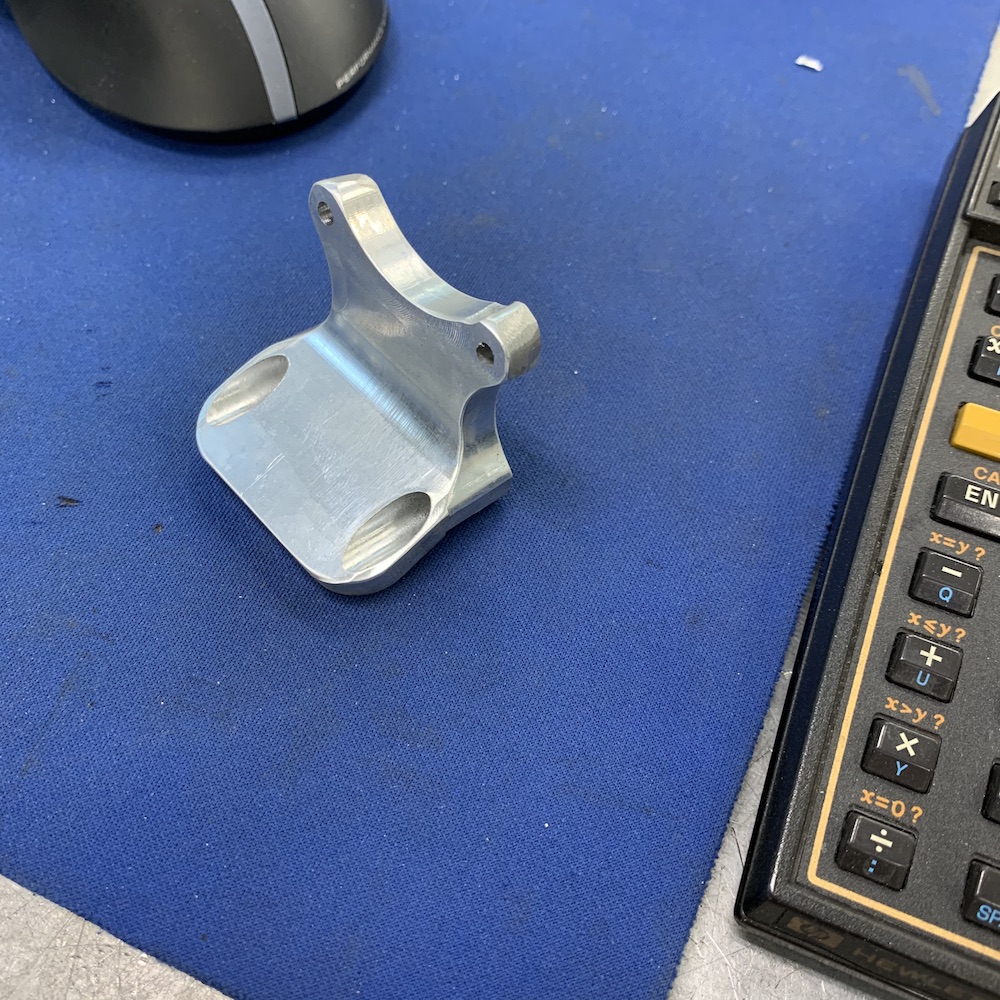
Yes, that is a Hewlett-Packard 41CV calculator, closing in on 40 years old and uses Reverse Polish Notation. 1, enter, 2, + Few will understand.
I win!
-------------------
What you see here is a true Unicorn.
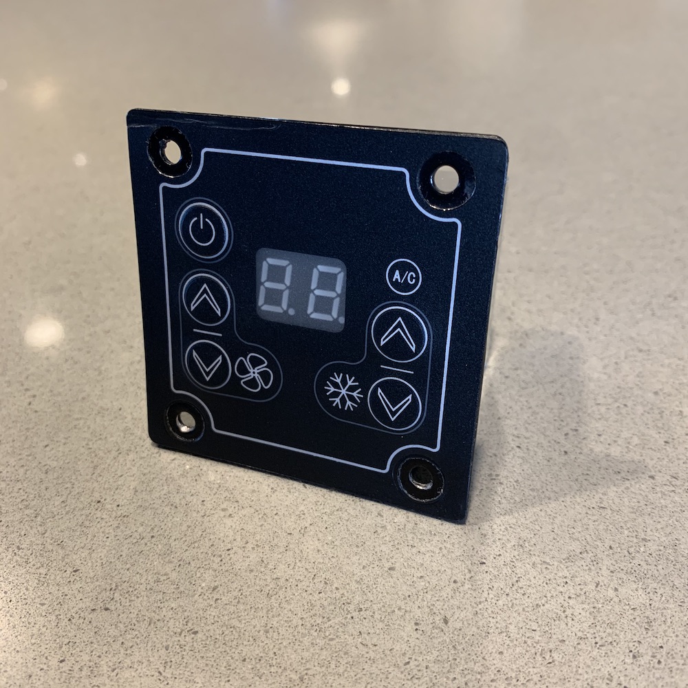
Once I got the 12v DC compressor in hand (end of October, 2019) I realized I needed a controller for it - or at least it would be easier to get one than having to engineer one (and my electronics skills would/will be tested by this regardless). So I got online and started searching the company, Rencool, that makes the compressor. Sure enough, there's a controller.
Being that TALON is down in Australia I ask him to do a little inquiry on the controller. A few messages later and its "No, they don't have it in 12V anymore. You're SOL."
Crap.
I get in touch with StreetFX, where I got the compressor and asked them about the controller. "Sure, we can get that. You'll need to contact us directly and we'll work from there."
I get in touch with them as asked (e-mail), send them links and pictures from Rencool and they say no issues on getting the controller. It'll take a couple weeks.
Hmmm... that seems too easy. TALON said no go... Oh well, I'll wait. Couple weeks go by and they say "We have it."
"Can I get a picture of what you're sending me?"
I get a picture of the actual control circuit in the top of the compressor. NOPE!!!!
Quick e-mail back and they were very apologetic and said they'd see what they could do about getting me the controller I was after.
Go for it! (I've not informed them that I'm aware of the lack of stock at Rencool).
I get an email last week: I have spoken with Rencool in regards to your order, they are still awaiting some components to be able to complete the unit for dispatch to you, they aren't able to give me an estimate yet as they are still awaiting their supplier to provide this information. There are a few orders held up at the moment due to this.
However they did note that due to the length you have already waited they would let their display model (at a reduced rate) be sold to you. If you wish to save a few $$$ and get one soon I could get this arranged for you.
I'm not sure on the total savings but I believe it will be at the very min of $100.00 of the total price.
I'm good with this!
I get a tracking number four days ago and THE ONE AND ONLY 12v controller shows up three days ago.
Now I have to figure out the HVAC system as this whole mess goes back together into one working machine.
Off to the shop! There's work to be done.
Feb 13, 2020
TheDoc
Getting your dose of Aussie lingo. Mate!
Me
LOL! Yup. I'm quite versed now.
When TALON and his buddy Smith came here a few years ago I had a bit of a time following conversation between them (especially with a bit of alcohol added to us all).
Then, a couple of years later, Talon and I spent a couple weeks driving/riding across the USA and I got really good at Aussie (especially with a bit of alcohol added to us).
I still want to see any of you mates from down under go get a bag of ice from a US convenience store. They won't sell it to Aussies, as they think you're asking for a bag of ass. (and I laughed until I cried)
I've also discovered that you all know 'Ol' Mate'. He's a common character, apparently. Even Ozzy Man knows Ol' Mate.
My wife had to have "having a root" explained too. (another laugh until I cried moment)
------
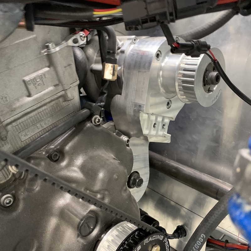
Got the clutch belt guard done yesterday. Have about 6 hrs into it.
First backing plate attempt wasn't quite right. The whole thing mounts only to the transmission as both trans and engine are rubber mounted so there's flex between the two pieces. That meant that I couldn't attach the cover to both - one end had to float. The transmission already had four bosses that just needed threading and I had my cover mount. First attempt ended up being clocked incorrectly by 4.8 degrees. Crap - more in the scrap bin.
Second backing plate went as planned and fits perfectly:
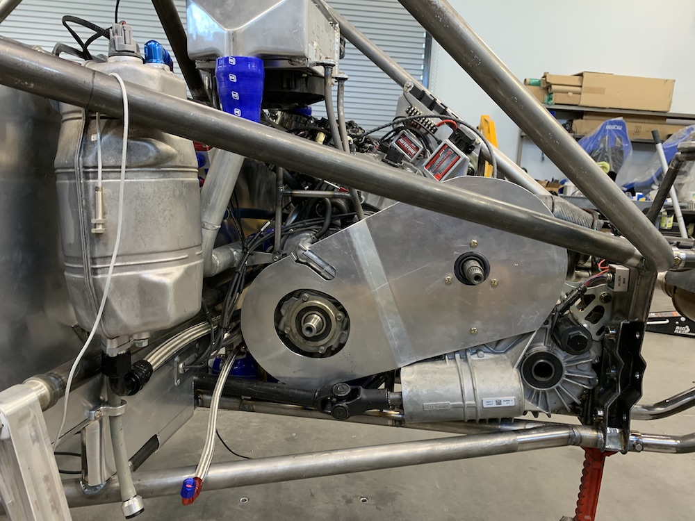
It has good clearance all around so getting to the belt (installing/removing) is easy enough:

Welding's getting better all the time. Seat time and help with settings has made a HUGE difference:
The issue, after getting it assembled and test fit, is that the backing plate for the cover is thin enough that it allows for some flex and that let it hit (probably vibrate) against the engine so I needed to stiffen the area. Fortunately (for once) I had a spare, screwed up, discarded plate that had the correct bolt pattern in it. A bit of time with a jig saw and some more welding and I had a dual plated area around the mounting screws. By only welding the outer perimeter and then using bolts in the center it makes the backing plate nice and stiff. No more wiggle.
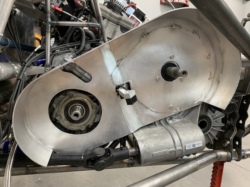
Still needs a little bit of attention to detail work done but other than that, it's done and I'm actually really pleased with this piece.
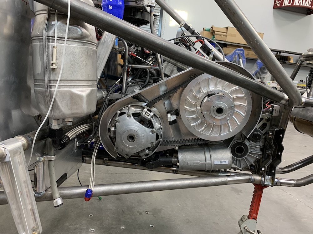
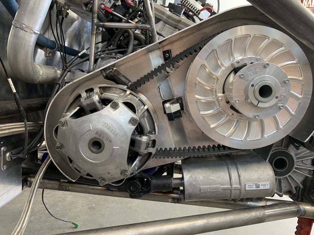
I've chosen to run the clutches open to the world instead of sealing them off like all the UTVs do. I've run thousands of miles in the two Deztazes, my old Honda Pilot and the Briggs cars and never had any issues with them being exposed to the elements other than when I had to deal with water and being that I live in the desert, water's not an issue (and I avoid the stuff like the Coronavirus when possible).
Leaving the cover open lets everything breath, get cooler air all the time instead of trapping it inside a cover and I don't have to deal with a sealed box that has to have an air intake and exhaust (plumbing). Simple is better. The only thing I see on a covered CVT system is time wasted trying to get the stupid thing off when you have belt issues.
Feb 15, 2020
Clutch cover complete.
The belt temp IR sensor (window in the top, middle) can now see it's target and I can put the cover on over the CVT reading IR sensors and arm w/o issue and swearing.
Have to say that I'm really pleased with this piece. I'm getting better with each piece I make - always satisfying to see progress.
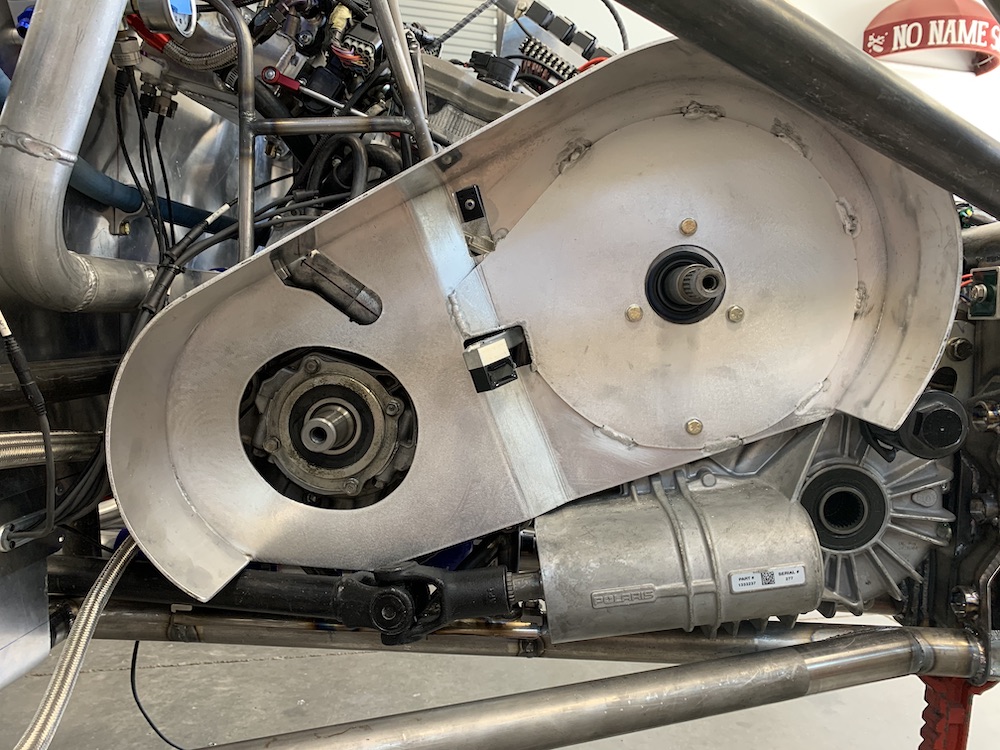
Just needs bolts in the clutches and they're installed.
Worked on the wire harness routing/mounting a bit on the back end while I was there. The little billet standoffs that I made a while back use a 2mm bolt to secure them. Tapping the holes is a very tedious, careful process and thus far I'm 15 - 0 when it comes to successfully tapping the tiny holes. (not broken a drill bit yet either).
Made this handle for a small drill chuck and have been using this tool for quite a few years now - mainly on R/C stuff:

For once I'm very pleased with the results:
The sled engine will retain it's electronics and charging system. I figure this is the easiest and safest way to keep things working. It charges the battery, runs the system, has enough spare power for some small components.
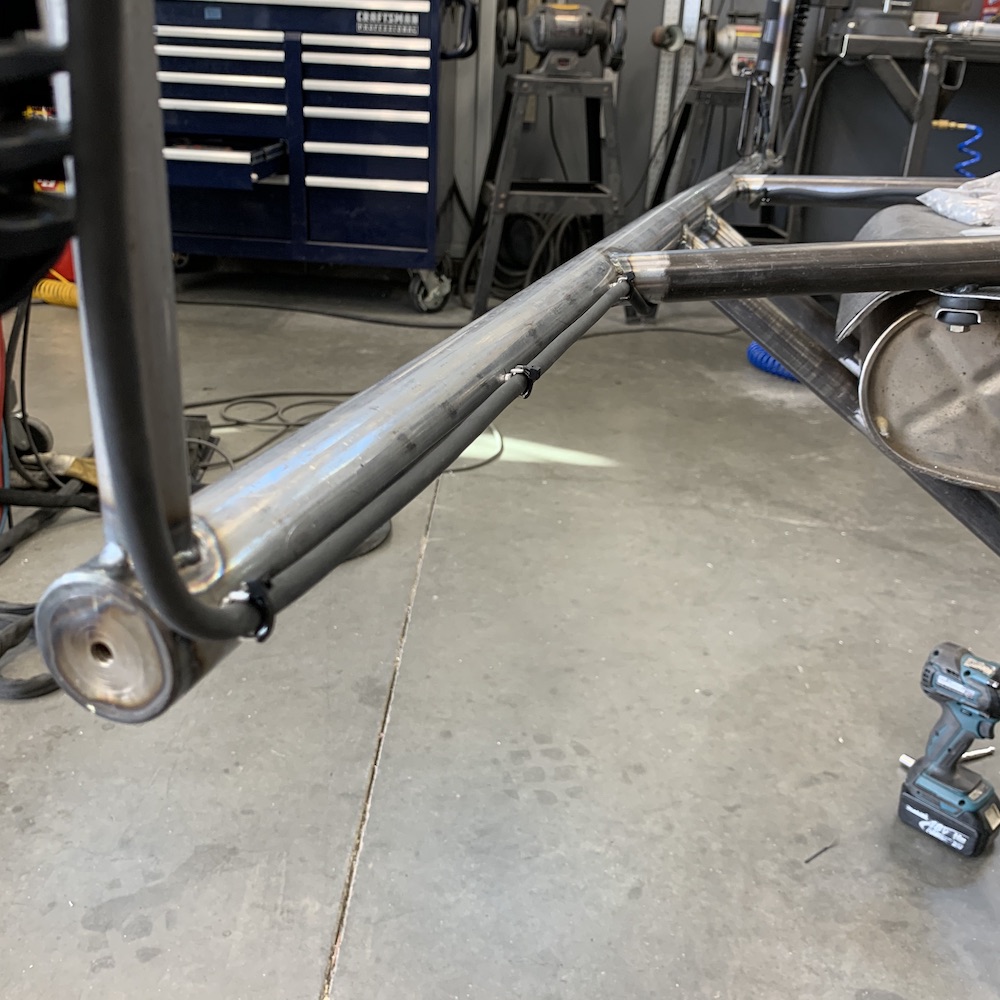
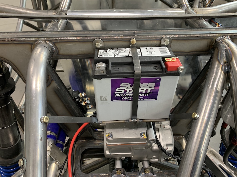
I've added a stand alone alternator to run the big stuff - A/C compressor, winch, electric power steering, lights. All that stuff is up in the front of the MR chassis so I was going to have to run a large gauge wire from the back to front from the battery, which isn't the best of things. Got me thinking - I have an alternator, high load stuff up front, etc... Why not just put a secondary electrical system up front? I can tap in off of the battery, have short leads, the alternator wire is the only thing I've to worry about now.
So I'm in the process of making a battery box that fits up in front of the shock bulkhead. Still have to add another leg and make the hold down. So far the battery fits like a glove - almost like the mount was made for it.
The challenge this makes is that the entire area that the battery and compressor are located in is going to have to get shrouded and insulated. Can't have the hot air off the radiator blowing on the components all the time.
Gonna work up front for a bit and wait for my supercharger to come back from repair. Once I get that I'll get it installed and then stick on the rear suspension. It's SO much easier to work around the back part of the MR w/o the trailing arms and stuff in the way.
I can see the light at the end of the tunnel!
Feb 16, 2020
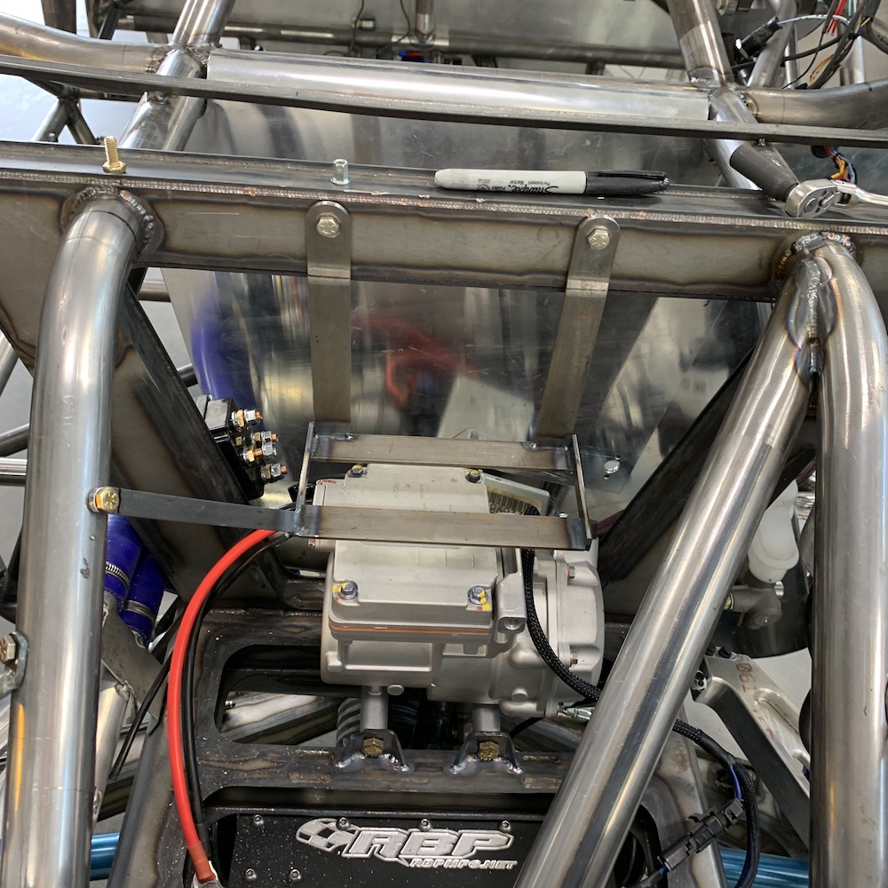
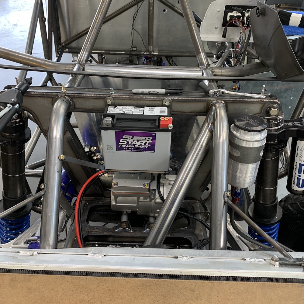
Front battery now in place:
Feb 28, 2020
Knocked out a few things yesterday.
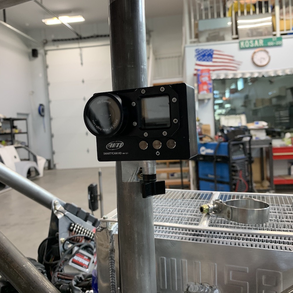
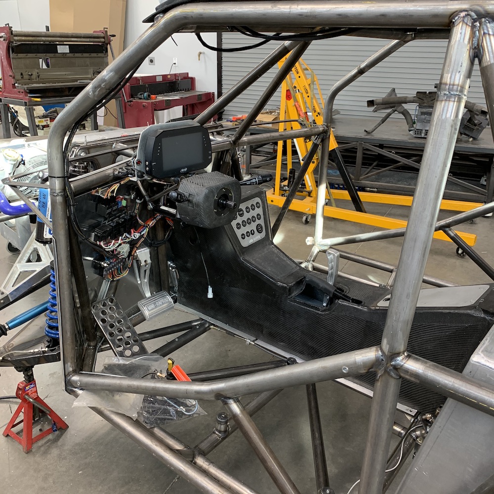
Ended up with an AiM SmartyCam (long story) so I may as well install it. It will use GPS and actually track (and I can make a course) where I've been. It also puts all sorts of data overlays on the video it takes.
Got the Beast back in it's home too. I'm curious as to the capacity - many miles, that's for sure!
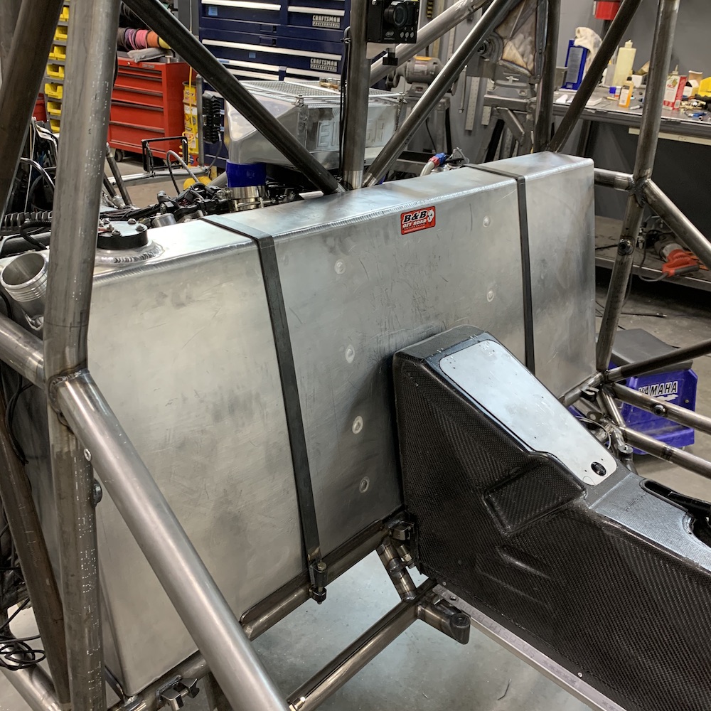
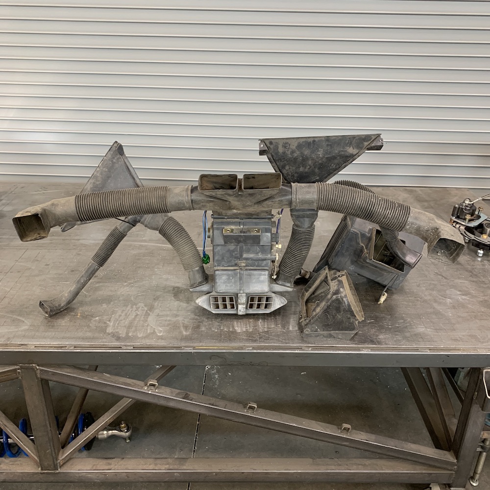
So this goes into the end of the center console, somewhere... Full HVAC system out of Samurai! It (heater core/fan assembly) kinda fits up high, inverted and backwards into the console and the steering shaft goes right through it. I'm gonna have to make a full housing for it and then make it all fit in the center console. Oh, and then there's the A/C condenser that's sitting to the right of the center piece. That's gonna end up in front/above of the passenger's foot area.
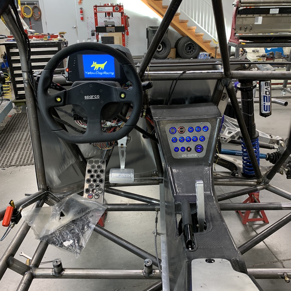
So assembly continues. Gonna get the steering in place today and see what else needs to be tended to, to get 'er up and running.
I'll not be messing with an upper dash and the HVAC system right now - I'm working on getting this running under it's own power so I can go get my street plates, test, thrash a bit and make sure everything's gonna work. Once it's proven I'll finish up the interior and some of the sealing panels and such. (still trying to wrap my head around how I'm gonna seal off the cab)
It's really pleasing that as I put stuff back in it all fits like it's supposed to. Whew!
Feb 29, 2020 Leap Day
Knine Racing rear axles installed.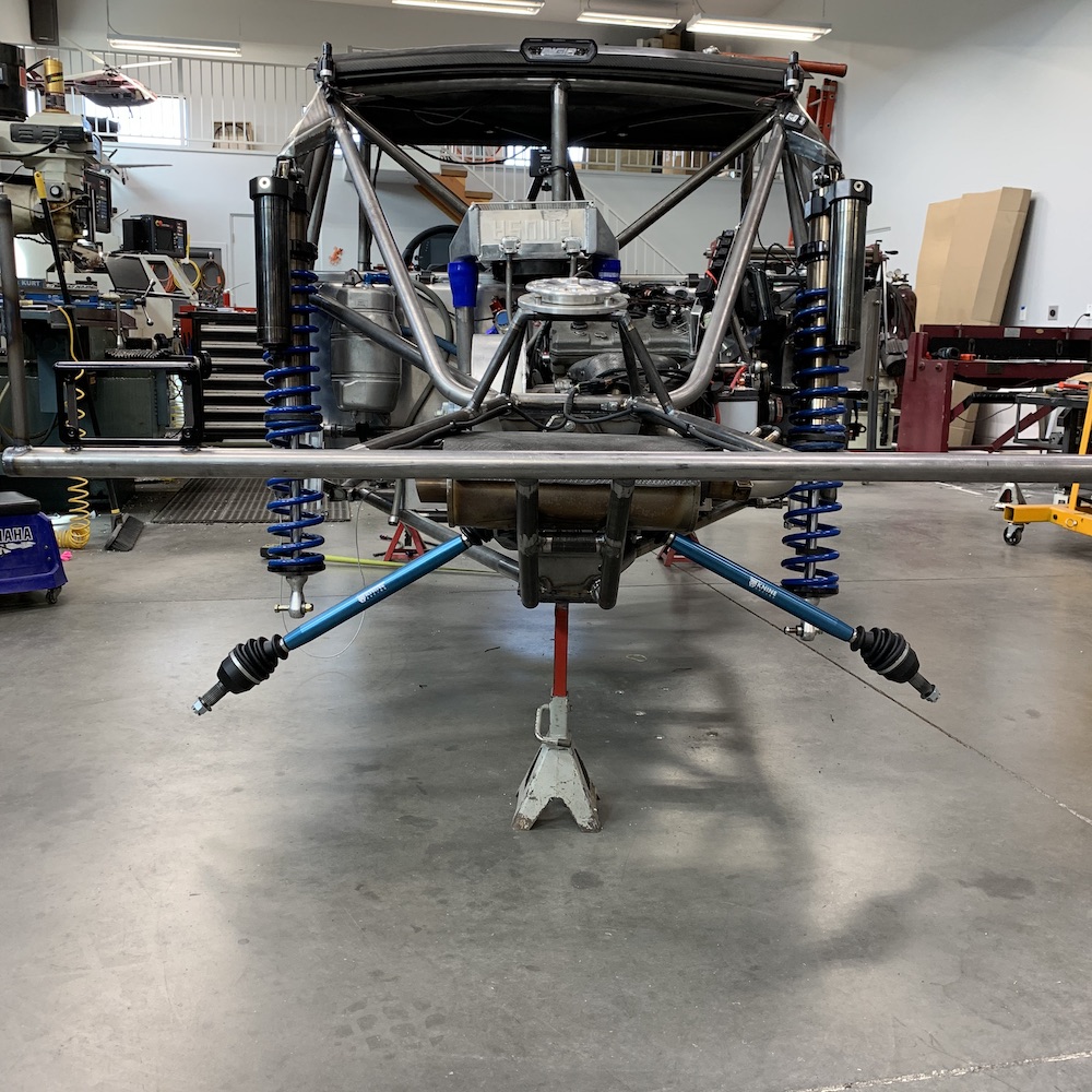
Rear suspension in place, right side done, left side has to come back off and have a few things added.
Slapped the left side (it was all assembled) on, started working on the right. As I put the carrier in I realized that there were no circlips holding the uni-balls in their homes.
Crap.
That means that the left side, while on the chassis, is missing all the circlips.
So, off comes the left side this morning, in go the circlips and then back on it goes. Arrrrggghhhh...
Mar 1, 2020
Yesterday was an odd day.
It started out with me dropping the dog food bowl first thing in the morning and what ever the bad juju that caused that followed me into the shop.
It would appear that I've somehow managed to completely f up all my hard brake line ends.
I've made these before.
I've done lots of them.
I have the correct tools.
I know what I'm doing.
Every one of the bastards leaks.
Arrggghhhh!
Stripped two nuts, fought with stuff, got all the circlips installed.
I guess on the bright side I didn't bleed at any point.
When torquing down the secondary clutch (55 lb-ft) I didn't have a clutch holder so I put a pry bar in the u-joint yoke of the output for the front drive train. Simple enough. Then put the trans into high gear and torqued the clutch bolt (opposite rotational direction as to what the trans sees from the engine). No fuss, no issues, no sounds, nothing other than the feeling of a bolt getting torqued.
Pulled the pry bar out of the yoke and now my trans is locked up. If I put it in park or neutral, the input shaft (secondary clutch) spins just fine. The moment I put it in any gear (R, L, H), the whole thing is locked up. I can't get the axles to spin, nor the output shaft for the front wheel drive (constant gear mesh - 4x4 is accomplished by locking the front diff in).
Not sure what my next move is (shoot the f'n thing). I have a query on the RZR forum as to if anyone has a clue. God I hope I don't have to pull the trans...
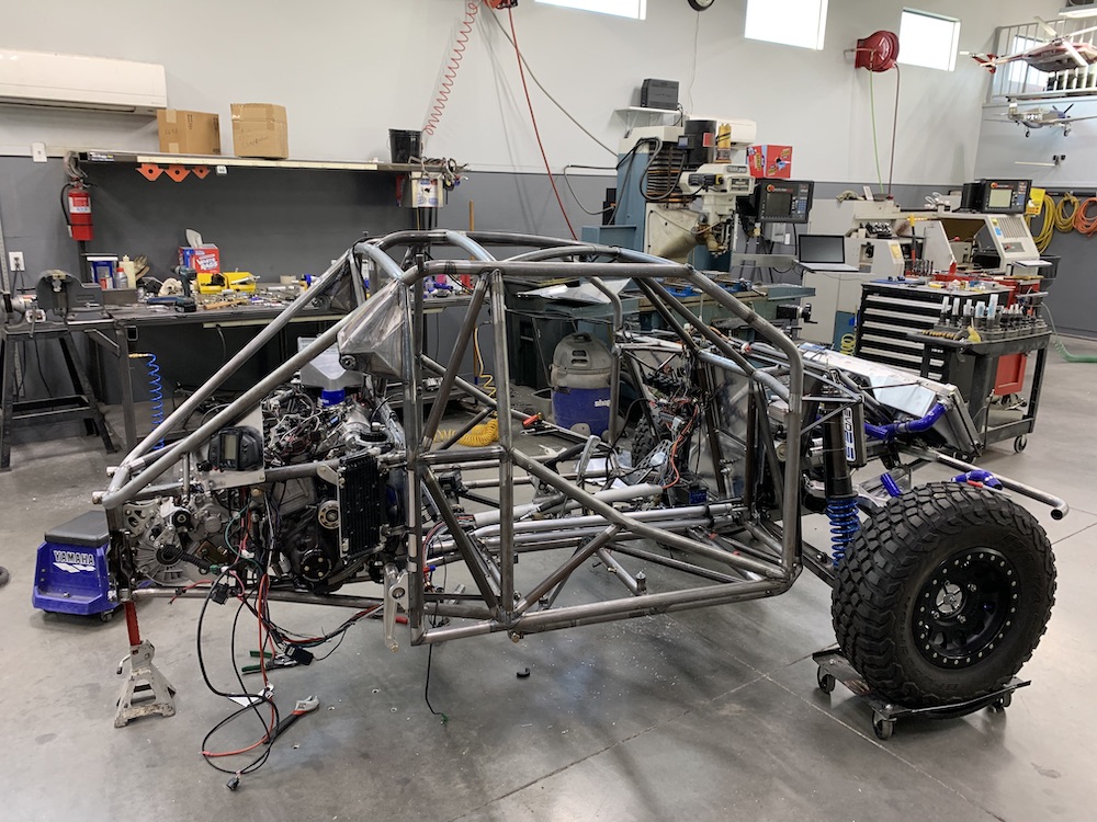
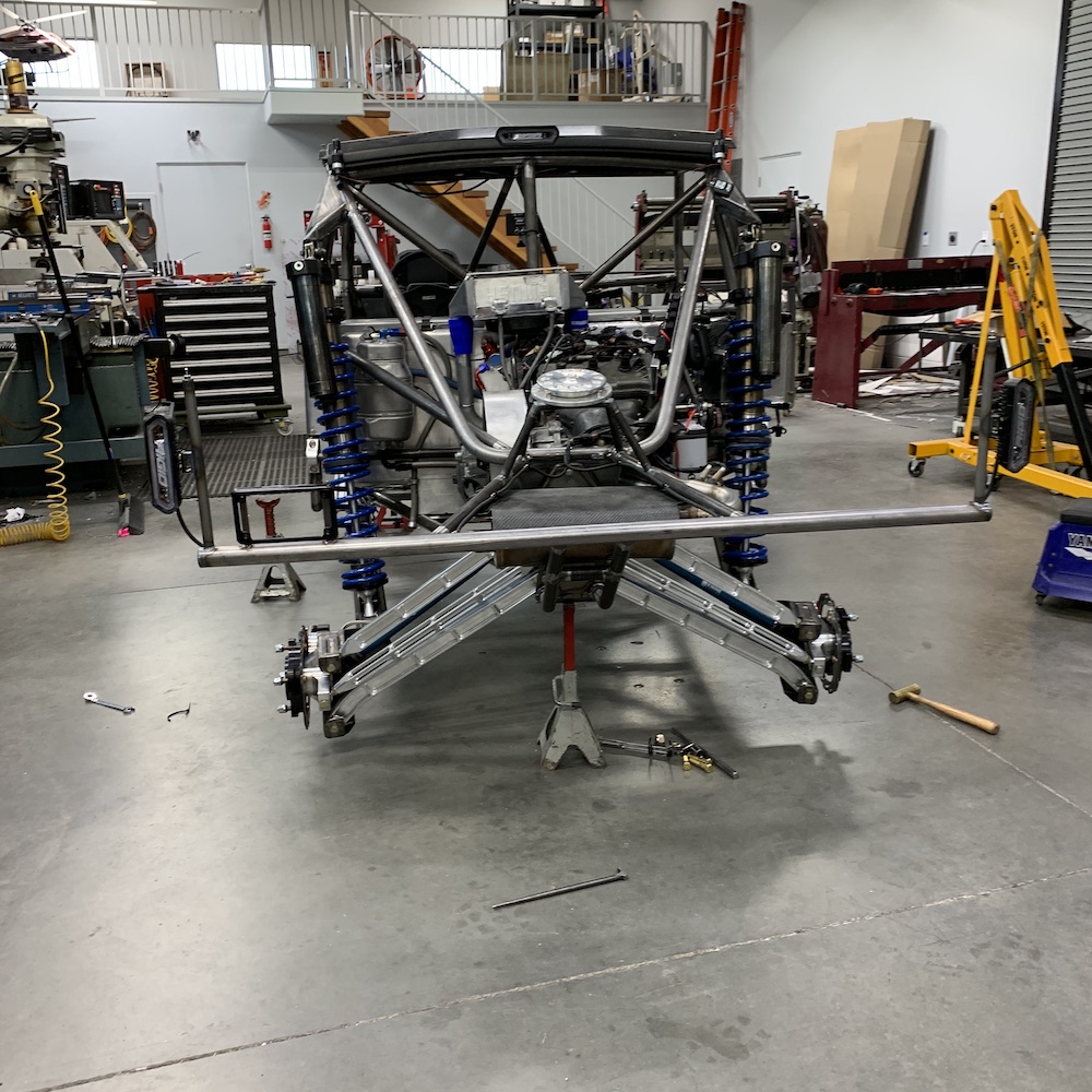
Assembly towards that first run:
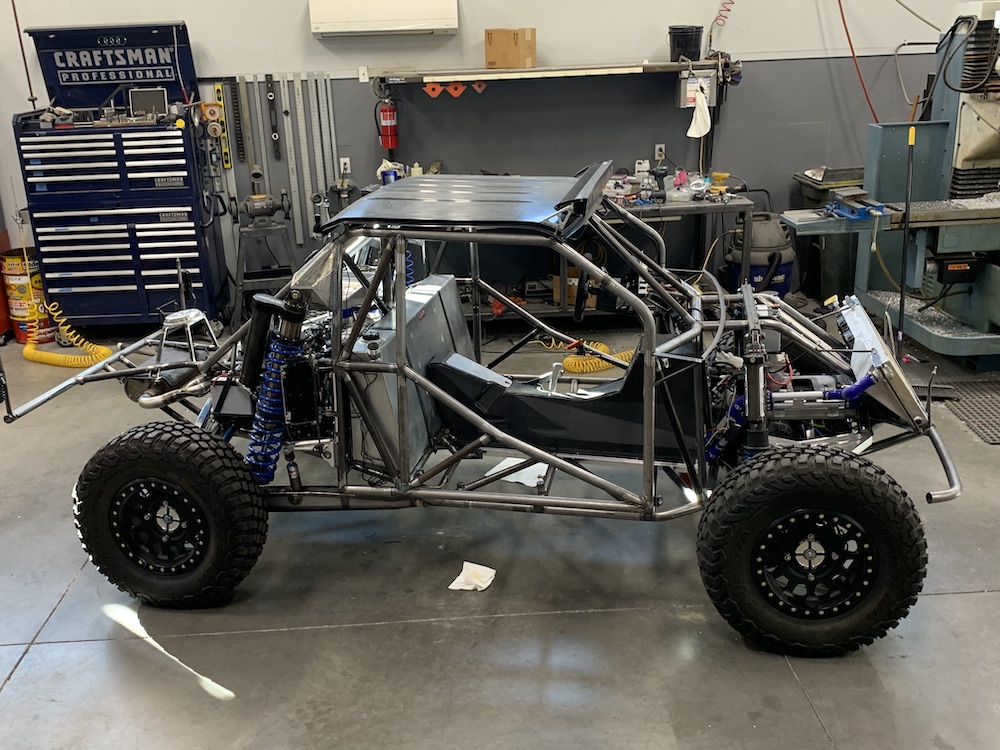
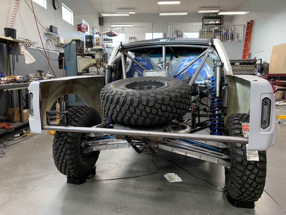
I've been guessing (pulled the numbers outta thin air) that the Mini-Raptor was going to weigh in somewhere around 1,850 lbs. Don't know why, it's the number that spoke to me.
Guess I was off a tad - expect it to be right at 2,000 lbs when completely finished.
The high cross weight is a direct result of a front spring holder and the preload it's put on the system and the weight of the engine biased towards the right rear.
Front shocks don't have tender (upper) springs and the spring rates are off anyhow (part of the reason for weighing is to put all the numbers into the [URL="http://f-o-a.com/foa-suspension-calculator/"]FOA Suspension Calculator[/URL] to find my spring rates). I still need to do a unsprung weight (chassis on jack stands, suspension fully floppy, weigh at the jack stands) check.
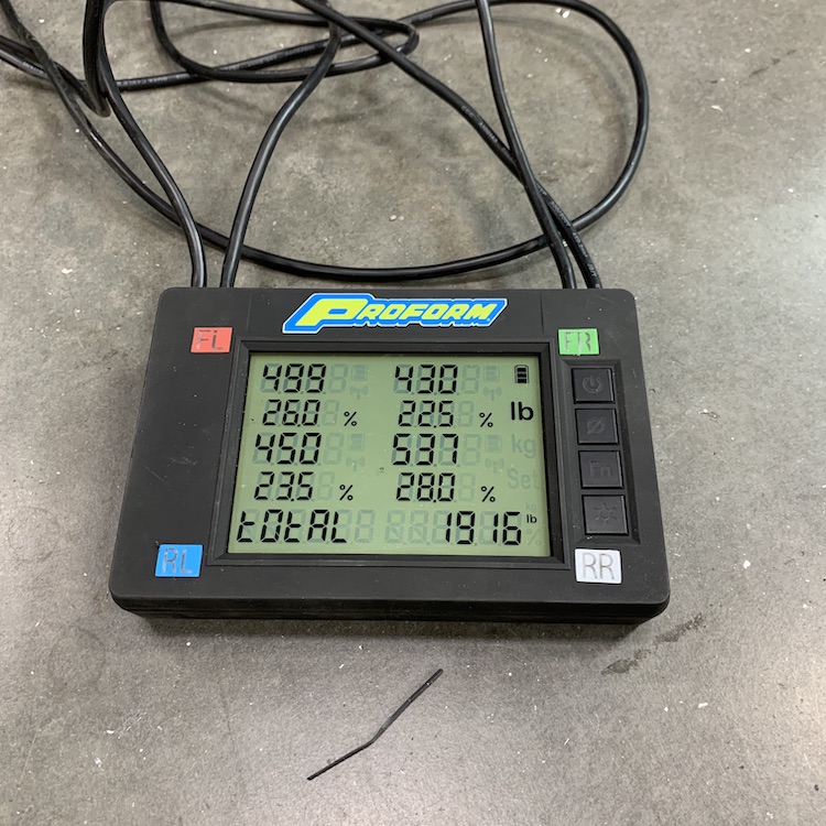
I'm really pleased with the weight distribution - it's gonna be close to a 50/50 front/rear split.
Even at 2K lbs, this thing is gonna rip. The Dez II was 2200 lbs and down 50ish hp. It had the same shocks, similar weight, travel and such and it was an absolute Cadillac in the dirt. The Mini-Raptor has a far superior suspension design so I expect it'll be everything the Dez was and more.
Light at the end of the tunnel is visible - flickering but visible.
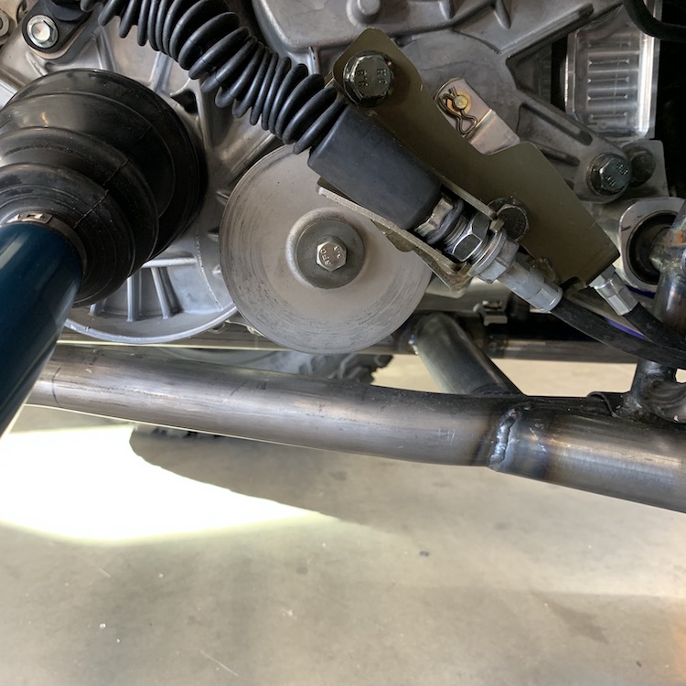
Mar 2, 2020
The Dumb Ass Behind the Wheel (this would be me...)
When torquing down the secondary clutch (55 lb-ft) I didn't have a clutch holder so I put a pry bar in the u-joint yoke of the output for the front drive train. Simple enough. Then put the trans into high gear and torqued the clutch bolt (opposite rotational direction as to what the trans sees from the engine). No fuss, no issues, no sounds, nothing other than the feeling of a bolt getting torqued.
Pulled the pry bar out of the yoke and now my trans is locked up. If I put it in park or neutral, the input shaft (secondary clutch) spins just fine. The moment I put it in any gear (R, L, H), the whole thing is locked up. I can't get the axles to spin, nor the output shaft for the front wheel drive (constant gear mesh - 4x4 is accomplished by locking the front diff in).
Not sure what my next move is (shoot the f'n thing). I have a query on the RZR forum as to if anyone has a clue. God I hope I don't have to pull the trans...
Okay, guess what our XP1K and the two XP900s that we used to own don't have....
And, as a bonus question, what DOES the XP1K International transmission have (besides a diff)?
It's not something that I've ever paid attention to ('cause it's not there...)
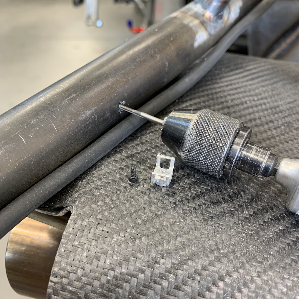
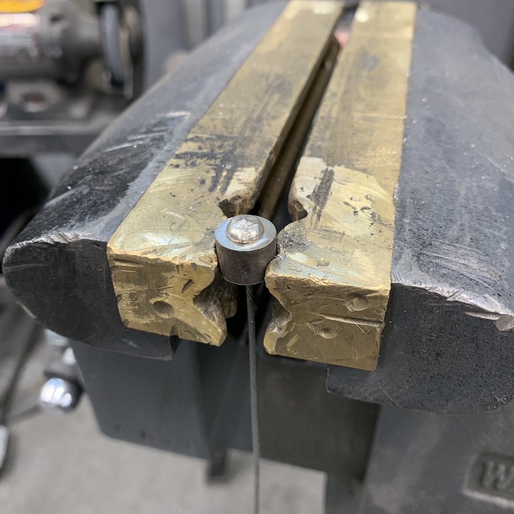
Yes, that's right, a PARKING BRAKE!!!!
And let me tell ya, that little rotor and cable activated caliper work REALLY DAMN WELL!!!
Hit the button on the lever, released the brake and the Mini-Raptor's a roller again!
Dodged a HUGE bullet. WOO HOO!!! (insert happy dance)v
The rotor is 4" in diameter.

Mar 4, 2020
Spent the earlier part of the day machining.
Had to make mounts for the dome lights that I could bond to the inside of the roof.

Whole roof harness is complete and installed now.

Also made more wire harness standoffs.
Mar 11, 2020
A myriad of things going on...
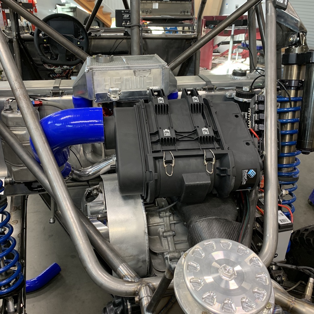
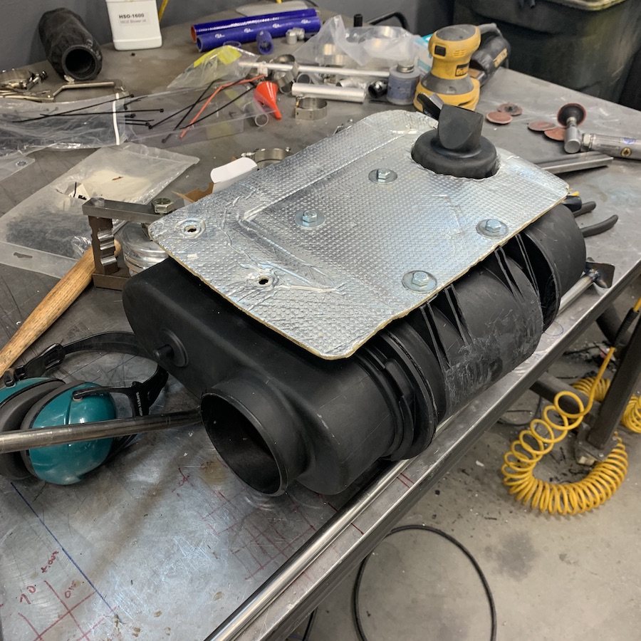
Got my air filter/air box ordered. Gonna use a Donaldson D090055 system. It'll fit between the intercooler and the spare tire (which may have to get moved back a couple of inches - of course. Why would everything fit simply???). It has a 4" outlet and the intake on the supercharger (which is still in Texas, supposedly getting repaired this week - only been gone 6 weeks when they said 3-4) is 2.25".
So I made a reducer and made it a velocity stack while I was at it. I've had a chunk of 6" diameter billet aluminum sitting on a shelf for YEARS - guess it was waiting to become a part and now it has:
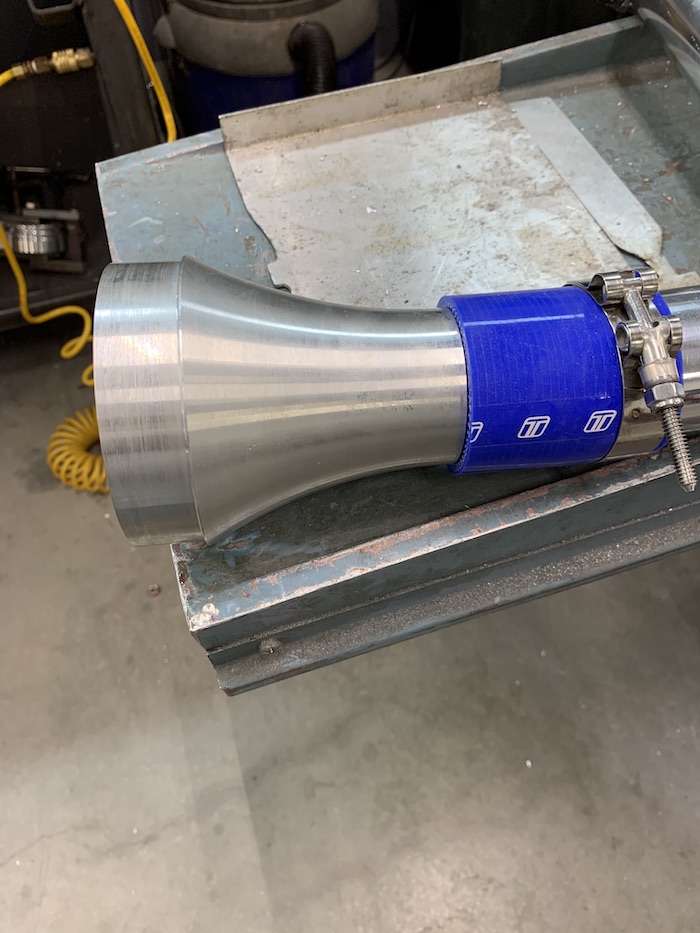

The air cleaner and the plumbing should be here in the next couple of days.
Whilst I wait, I chase leaking shit. I'm tired of leaking shit...
Been chasing self induced brake line leaks for two days.
Not sure why but I single flared the lines on the first go around (months ago)
So I redid the lines, double flaring them.
Seats still leaked (and I wasn't smart enough yet...)
Frustration....
CSI time:
Flared a junk piece of tubing, ran a Sharpie on the mating surface, screw into adapter, look at witness marks.
Yup, screwed up spots.
Cinching them down ended up screwing up the little brass tit that's the seat of the brake line adapters (hard line to braided).
Fortunately the little brass tits pop out of the stainless adapter bodies and I have a lathe.
Quick refacing of the tit, reinsert, put "new" adapter in and it looks like I've beaten the brake line leaks.
All was dry last night when I left the shop. I'm curious if there are any puddles this morning. I'll know in a bit.
Actually was semi-smart on the cooling system.
BEFORE putting any wet liquids in it (air is a dryish liquid), I pulled a junction line by the radiator, plugged each end it was in, thus sealing the system, put 14.5 psi in the system and walked away for 90 min.
Come back to 3.1 psi. Shit, leaks somewhere.
Thought about the system, KNEW the tubing on the engine was good (remember - I popped myself in the nuts with a plug because it holds pressure well). Isolated everything from the radiator and pressurized it to 8 lbs.. The next morning it was at 5 psi. It's not enough to consider "a leak" and hopefully I'll have dirt witness marks at any micro leak that I'll be able to take care of when I do the full final assembly thing.
Coolant leak has been isolated to the radiator. Gonna block it off, pressurize it and bring it to our pool - only body of water large enough to dip it in and look for bubbles. Sharpie the spots, head back to shop, weld, repeat seal check. Once that's sealed, the cooling system's ready to be filled. Woo hoo! That'll be two liquid containment systems done.
I won't be playing with the radiator today, though. We're actually getting rain and the stuff's cold and wet and not pleasant to work in.
Still have to add oil and see where it decides to come out. It didn't leak when I had it running last time but that doesn't mean squat. Something WILL.
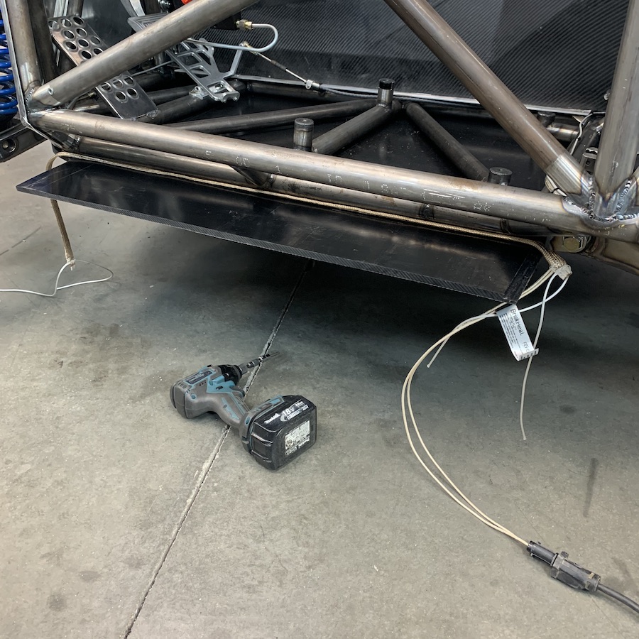
Gonna start on the belly panels today.
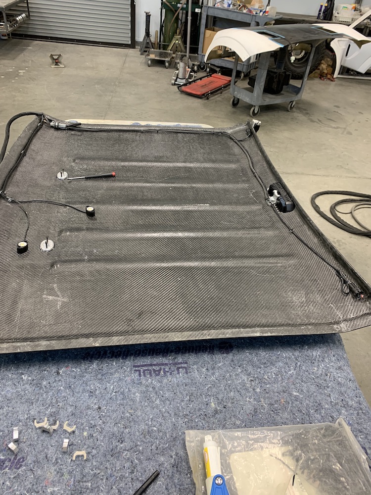
Mar 12, 2020
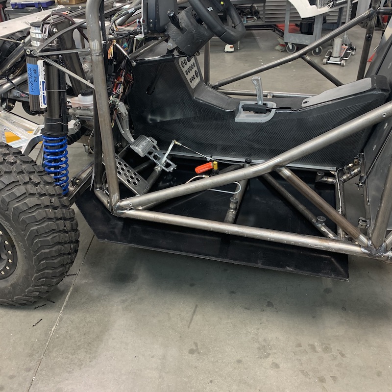
UHMW (Ultra High Molecular Weight plastic) front belly pan.
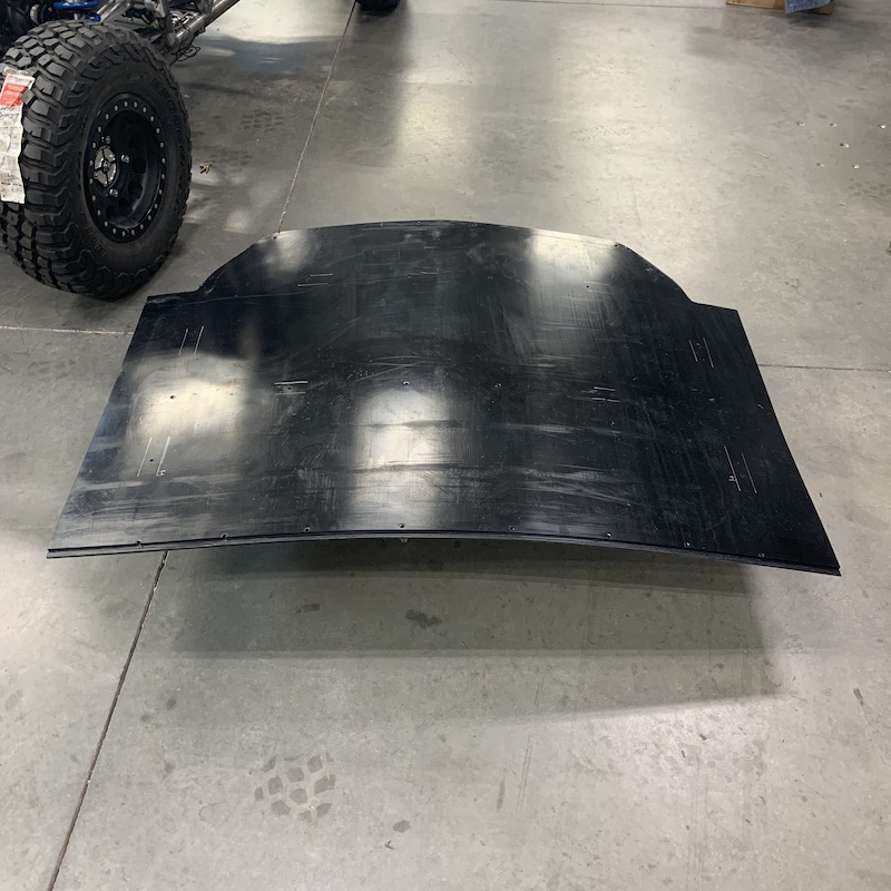
Rear edge is lipped, rear pan will have matching lip that will hold it in place.
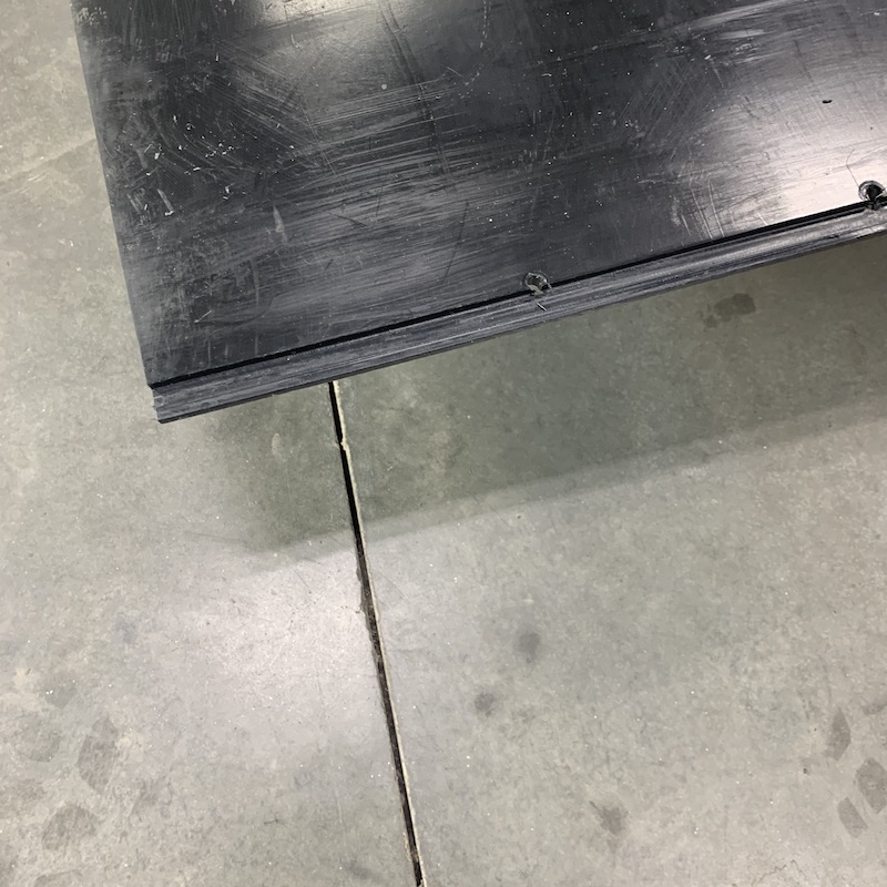
Still have to form the edges. They get bent up to seal the lower frame step up on the sides. 28 bolts hold it on. Laid on my back all day drilling holes and all the chips sucked! Hot, pokey, sharp. Have more to do tomorrow too.
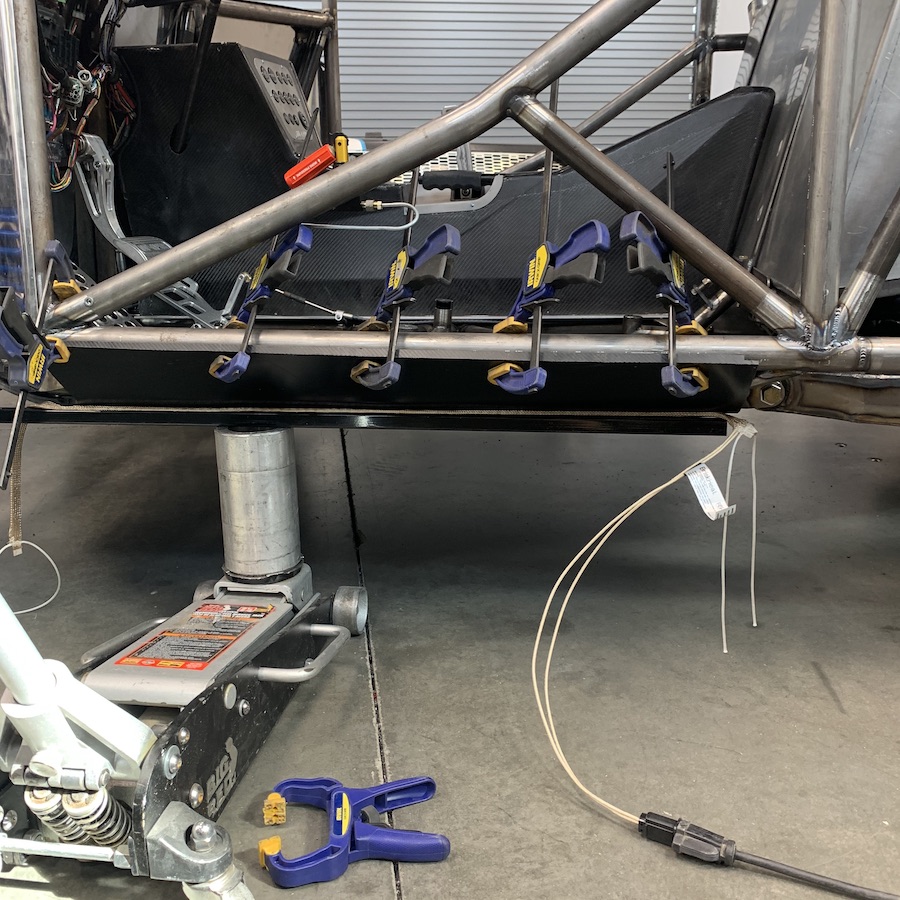
Trimmed and ready to fold - not sure how yet.
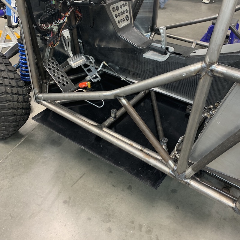
May be hitting up a buddy with a break. (Brake?). Bender thingy. Not sure if his is wide enough.
I keep hearing that a heat gun will work. On a .375” thick, 42” long area? Don't think I can get the heat evenly distributed.
Was told by the plastics guy to slit half to three quarters depth, spaced about .125” apart, three or four times and it'll fold nicely around the tube. I like this idea.
May look into some "heat tape" - 48" long, capable of 1400F. Lay it in place, heat things up slowly, bend to fit.
Mar 15, 2020
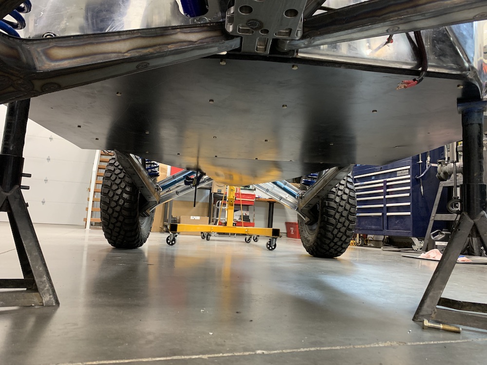
Belly pan, front and rear, installed. Waiting on heat tape so I can bend the edges. Should be here tomorrow. Amazon's amazing...
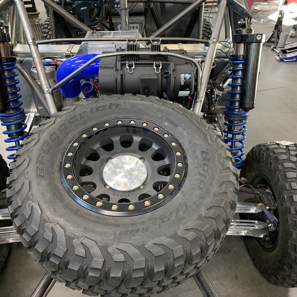
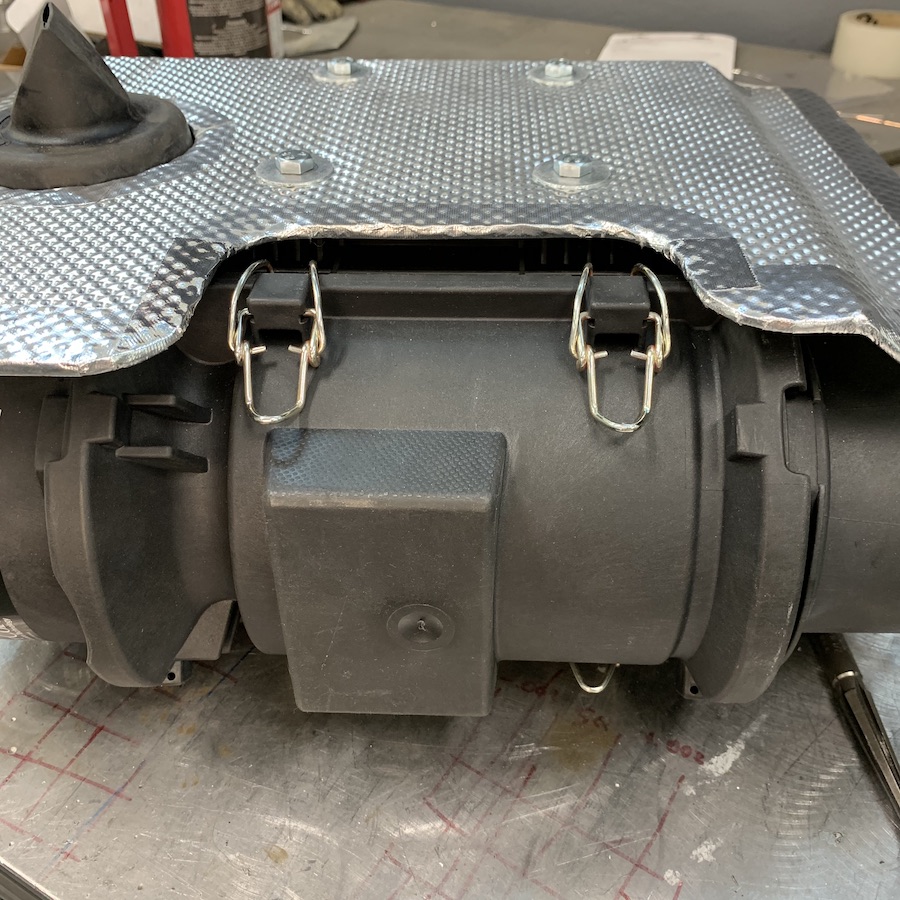
Got the Donaldson airbox installed and am now waiting on the supercharger so I can get it all plumbed.
The filter is an industrial setup designed to be used in high dust environments on engines that just chug along for hours on end. It's capable of flowing about 1/3 more CFM that the engine can pull with supercharger at full tilt boogie.
Preliminary fitment check. Yeah, looks like it'll just fit:
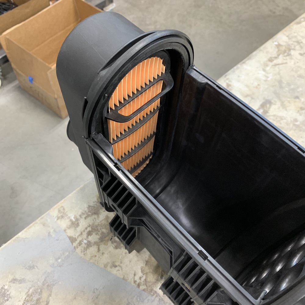
Airbox is pretty cool. It's multi chambered and multi elemental. From left to right: Airbox lid, main filter (white) and secondary filter (orange) and the body:
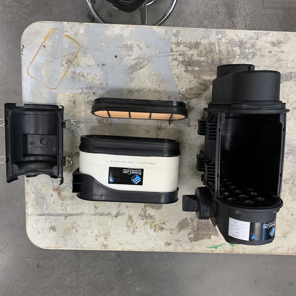
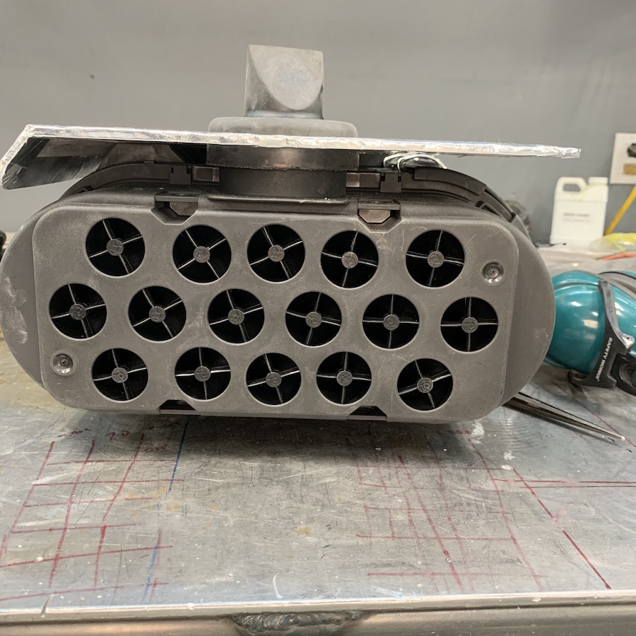
This end is like a Dyson vacuum cleaner. Each one of those holes is a little vortex generator. It spins the dirt outta the air and lets the majority of it pass right on out of the airbox, before it even gets to the filters.
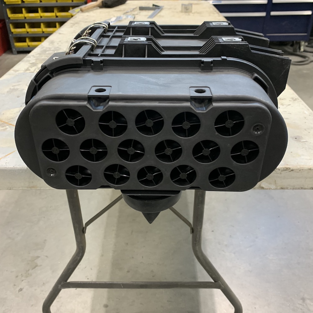
Elements are accessed through a lid that's held on with four spring clips. You can see the feed holes out of the vortex section on the right, inside, across the open spot from the filter.
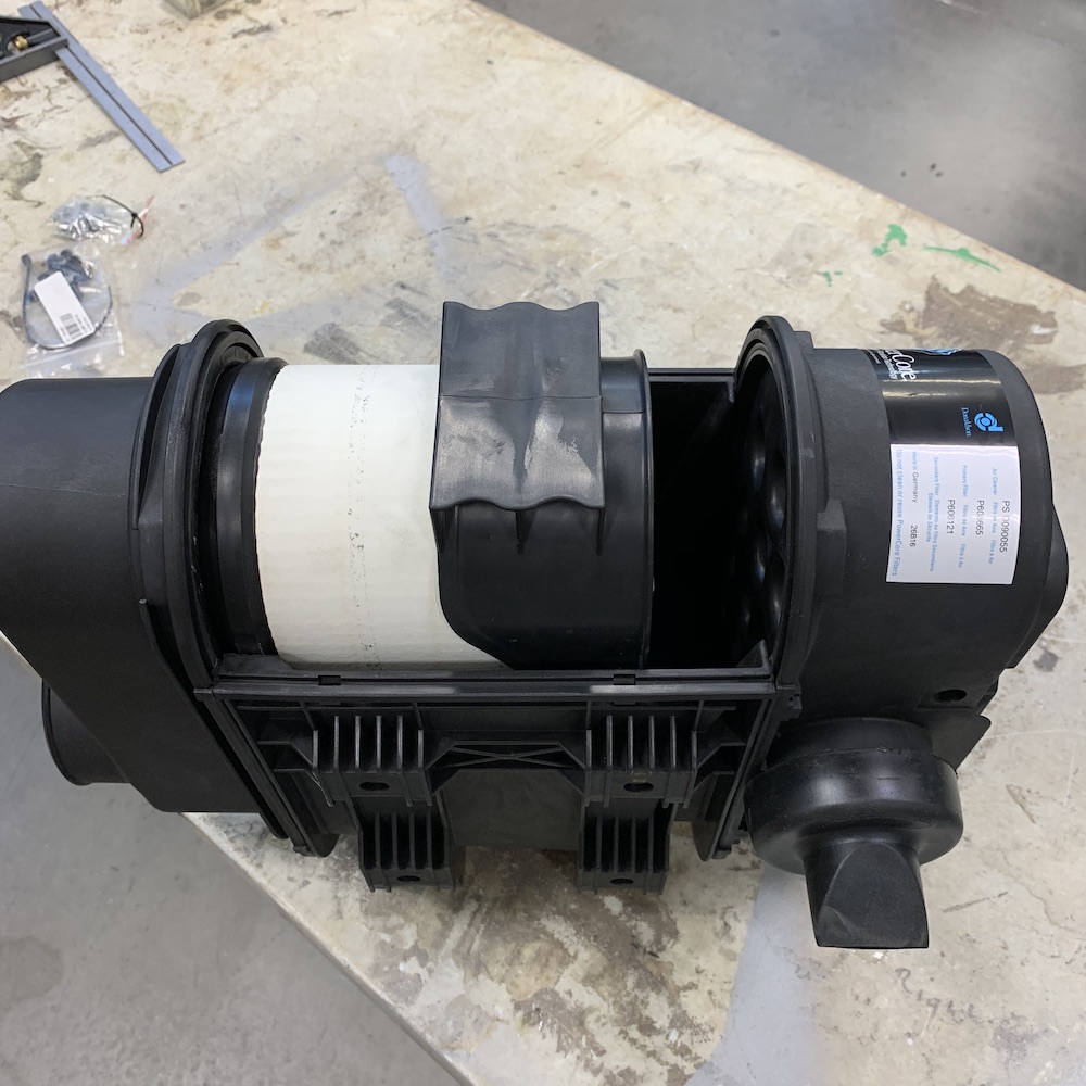
Secondary filter:
Output (4") side of the airbox:
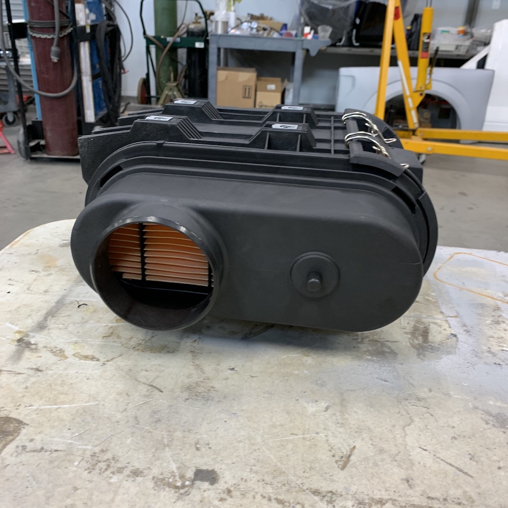
It's really tight but it fits perfectly:

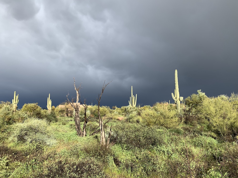
One of our rare rain days here in the desert.
Most people hear 'desert' and instantly think sand and no plants. Wrong - it's BEAUTIFUL here and remarkably green.
Heck we've had rain all week and are actually over our average amount presently.
That'll change in a couple months and we'll be begging for wet stuff to fall from the sky.
Mar 20, 2020
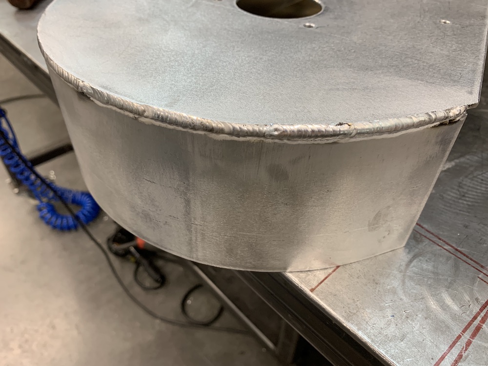
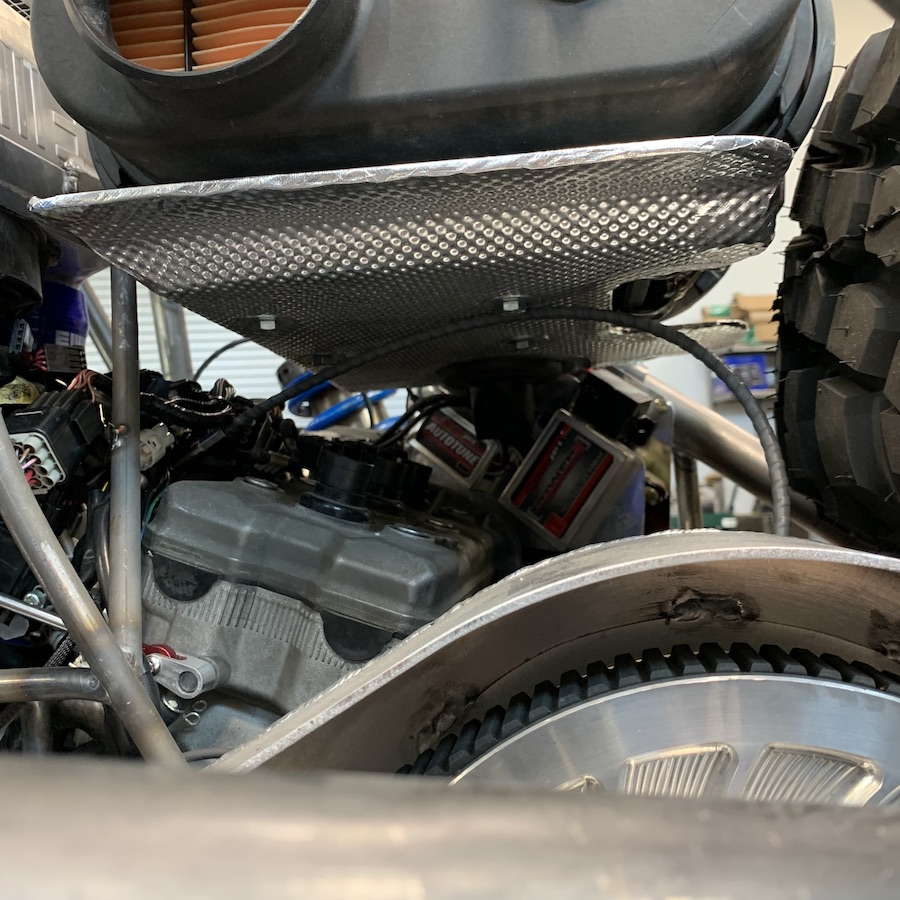
Heat shield done.
Process of development through completion:
Old XP900 heat shield that I've been saving for something like this:
Shield fitment:
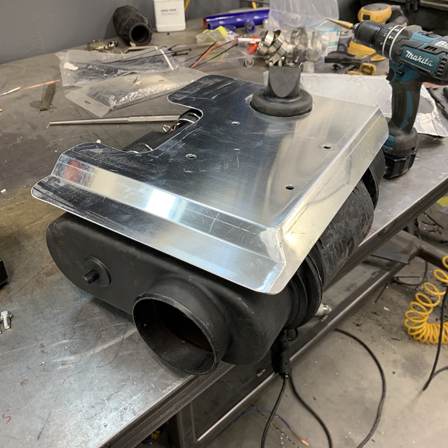
Covered with insulating sheeting, edges taped and ready for use:
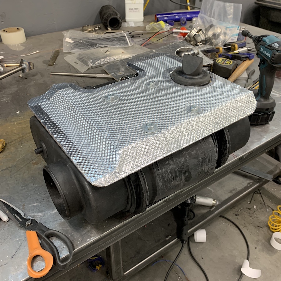
Nice air gap between the shield and the air box - should work well.
Made sure I still have access to the filter access lid:
Installed:
This little heat tape thingy is pretty impressive:
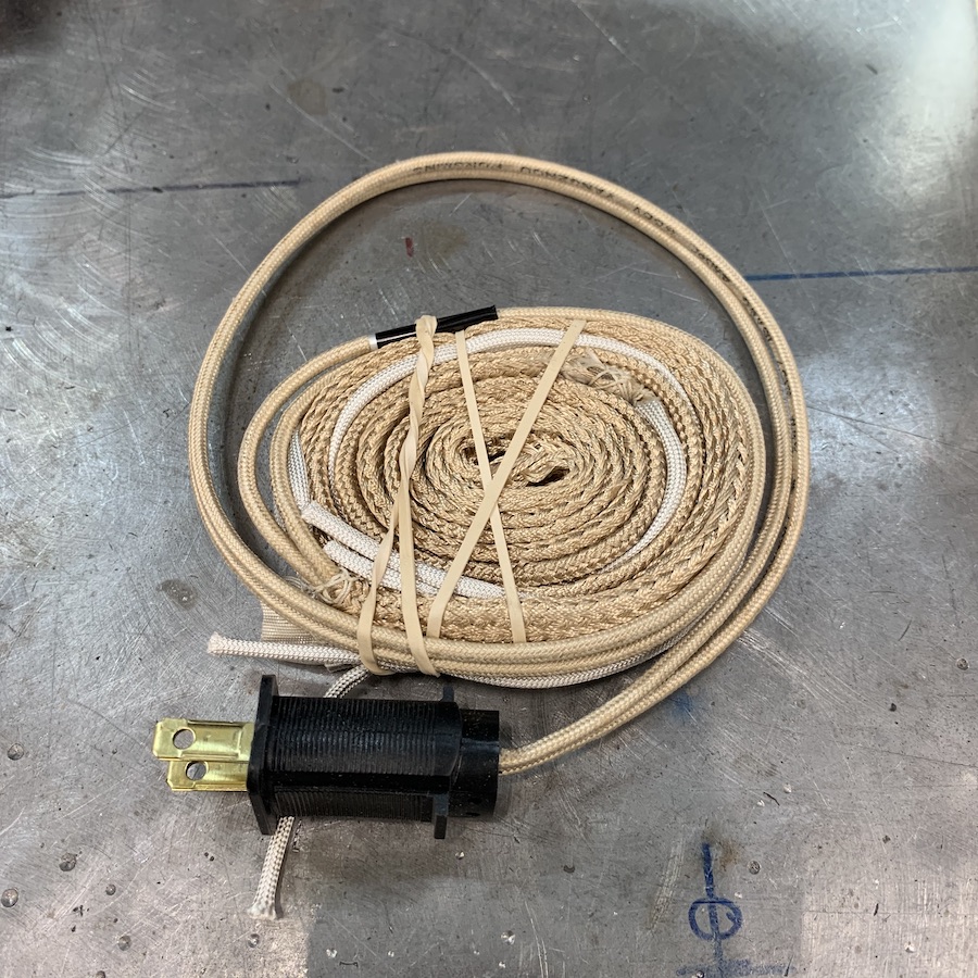
Put it between the frame rail and the UHMW plate and plugged it in. 35 minutes later I can't touch the bottom and the edge is starting to droop a tad:
So next I put it on the underside of the panel and plugged it back in for another 10 minutes.
That allowed me to bend the edges up and form my side areas:

The Mini-Raptor LIVES!!! March 18, 2020 1:21 p.m. she moves on her own for the first time. As much as I wanted to step on the fun pedal and see what she'd do, I don't have front springs on the shocks, the supercharger isn't installed, the air filter system's not attached. I just wanted to see if it was gonna move.
I watched the AiM dash as I heated it up and ran through pressures, temperatures and such. The thermostat bypass system works - temps it 201 and then whoosh, the thermostat opened up and the water temp dropped back to 135 and then started climbing back up to operating temps.
Outside view - phone rang just as I was pulling back in so the video cut off. Crap...
Inside view:
Presently assembling everything I have to put it back on the scales and try to dial in my weight so I can go get springs and get this thing suspended.
Apr 1, 2020 April Fools!!!
Front springs (pair of 400# 12" per shock - gives me a 200# rate) installed.
Rear end alignedGot in another run. This time I played with the fun pedal a bit.
I'm having an issue with cooling - there must be something in the line. It worked just fine the other day, now it appears to have some sort of blockage (probably another paper towel, knowing my history) and isn't getting the hot water to the radiator. I can see/feel/tell when the thermostat opens up so I know that's not the issue. Arrrggg. I hate dealing with fluids.
So... been a day. Fixed my old XP900's lower front a-arm (it got dorked this weekend, I have tools, owner and I have agreement)
The MR is having funky cooling issues. My first time cycling it, it worked. Temp goes up to 200, thermostat (which says 71C - 160F) opens, temp drops, thermostat closes, temps up, blah, blah, blah - does this until it levels out around 200. Good. That's what I wanted.
Nope, then it does the "I'm hot" and spikes up to 220 then 230. Off with the engine. No steam, no hissing.
Yesterday I drained, changed thermostat (holy f**k not easy!), filled, burped, started, warmed to fan on.
Hot water goes into the line that goes to the rad at the back of the tunnel. No hot coming out at other end. Wtf?
It worked fine the last time.
Very confused.
I checked the lines today for obstruction (the little 40 buck video on a flexible stick thing I picked up at Vato Zone is killer). Was able to look into all the lines and there's nothing there that shouldn't be.
I picked each end up with the engine lift. Burped the bypass that way.
Gonna look for more air tomorrow after I finish something else.
Changed direction for a few:
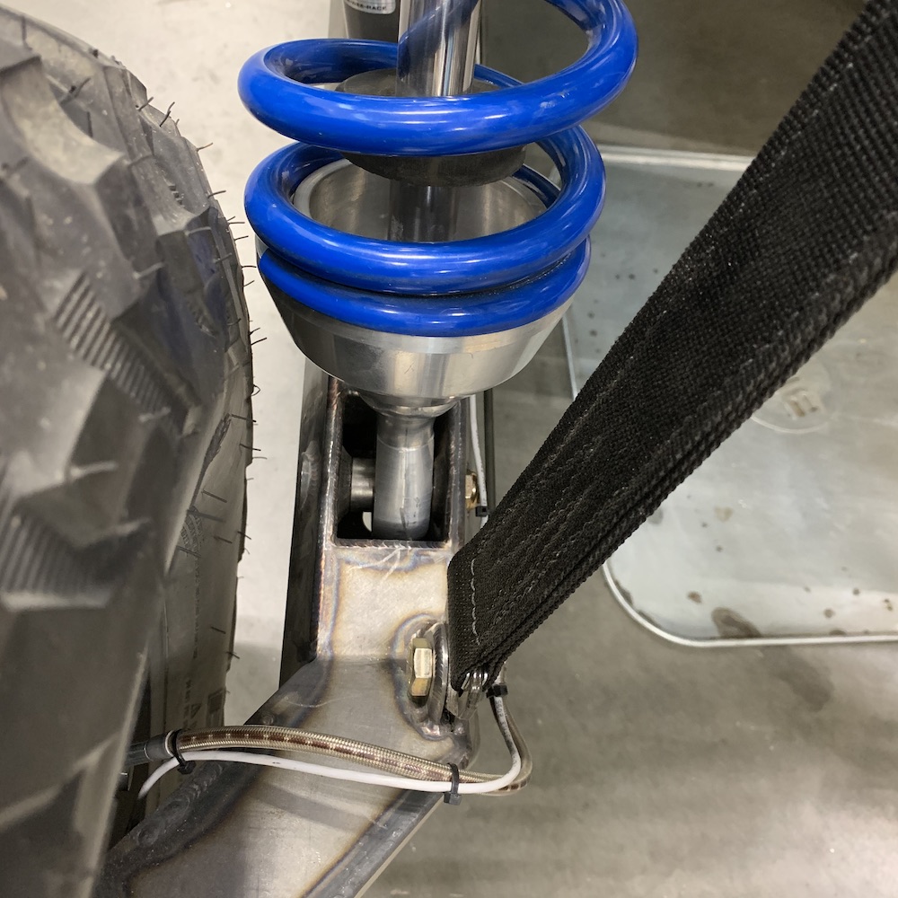
At full droop the rear wheels toe in. They were just touching the bottom spring perches. Not good.
So I tried adding just a little toe out- basically enough to stop interference. Made rear end squirrelly as shit at ride height.
Out with more big hunks of round stock and I'm making perches that move the springs up 2.75” and clear the tires.
Got the spring side of each one done, programmed the other side but didn't get a chance to run it. Will finish tomorrow.
Pix later.
Apr 4, 2020
Second run showed that a tad bit of toe out makes for a really squirrelly back end. Reason I'm having to try to get my toe adjusted is because (like so many aspects of this build) there's a slight clearance issue at full droop.
The wheels toe in as the suspension droops out and right at the limit, the tire tags the shock spring collar. If I adjust it so that there's clearance (minimal at that), as the MR goes back to ride height the toe in the rear becomes toe out and the back end gets all loose.

Decided I'd just move the spring perch up so I had clearance and the issue would go away. (hoped at least...)
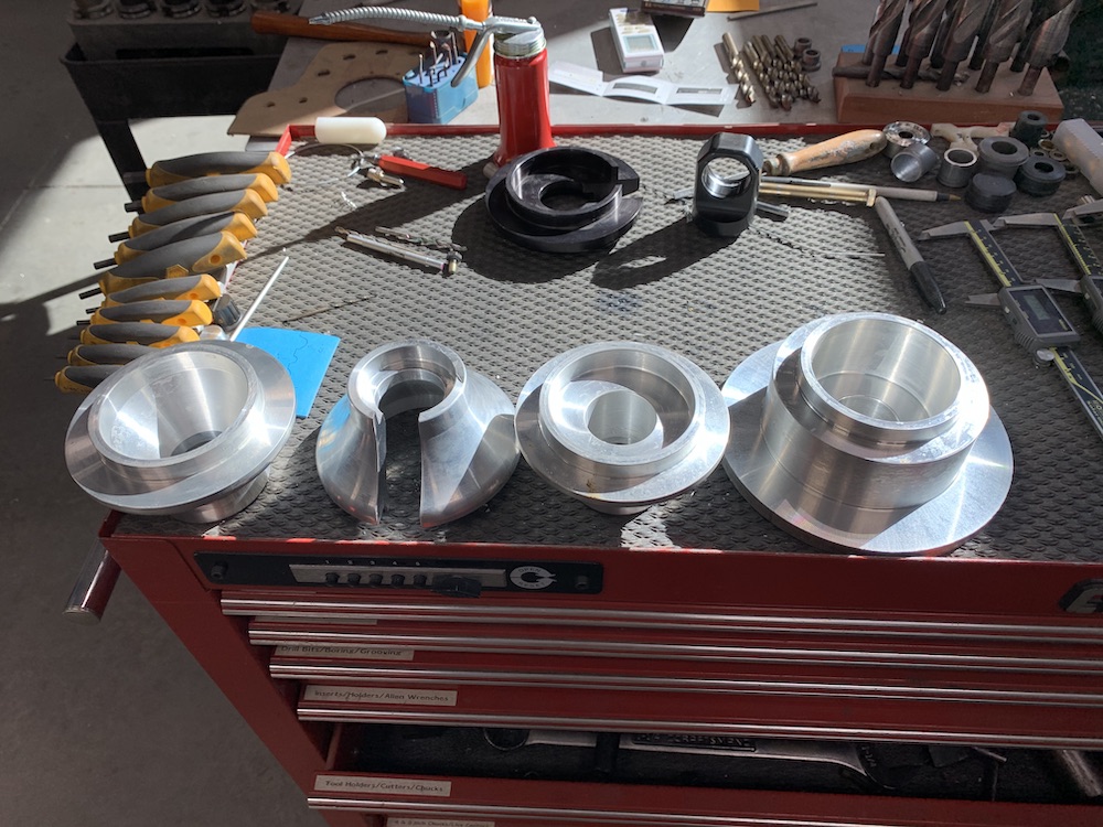
Fortunately I have had five large slugs of round stock aluminum in storage for years, left over from a long gone machine shop project and I have a lathe.
Left to right:
First two, one with slot, one showing the nicely blended, tapered, lightened inner part that doesn't work. (shit).
Third one - see the nice flat for the shock to bottom on? Yeah, perfect! Just 2" too high. (shit)
Far right - see how deeply the cup goes now? Yeah, back to stock spring perch thickness. No travel lost.
Out came a pair of billet slugs, measurements made, lathe programmed, chips made.
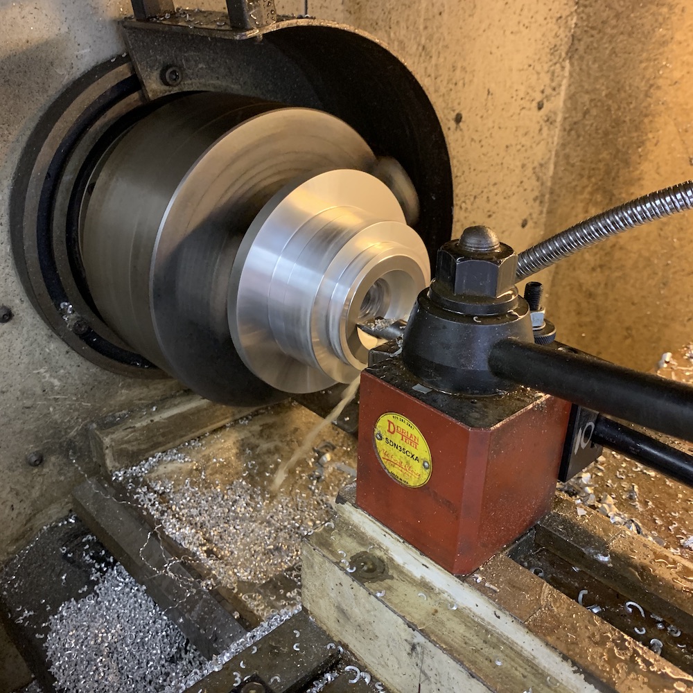
Two nice new spring perches that have moved the lip 2.8" up are produced. One's still in the lathe, finishing, one's been slotted to fit over the shock shaft so I could install.
Saw it as soon as I placed the perch on the shock - I'd done a tapered inner section (saving weight). No, that won't work... The shock body has to hit a flat surface when it bottoms. This is tapered just right that the shock body will wedge itself in the cup the first time they meet.
Shit.
Okay, it goes to a flat. Easy enough. Quick reprogramming of the lathe and we have a third cup.
Held it up with pride, admired, patted myself on the back. It looks REALLY NICE.
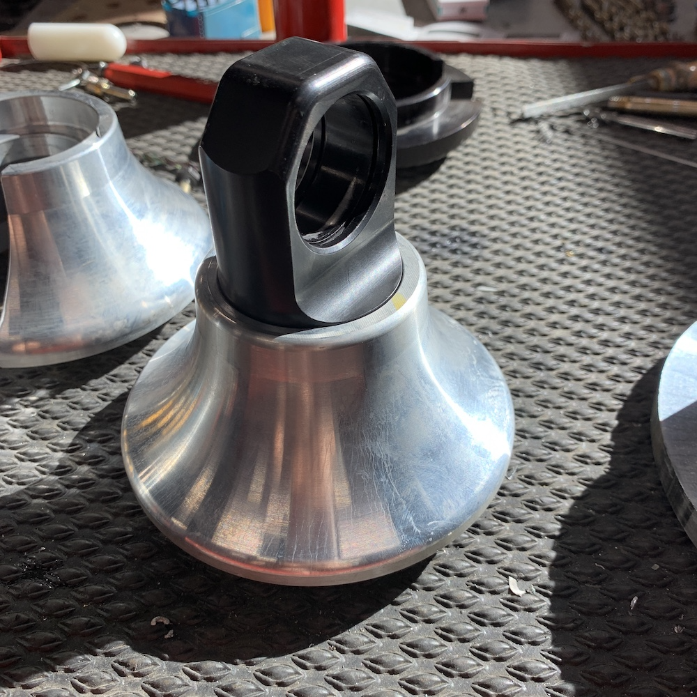
Walked over to the Mini-Raptor, held it up against the shock (no slot cut to put on shock yet), admired my nice flat spot for the shock body to bottom on and realized I'd just removed 2" of shock travel with my nice flat piece.
Shit.
Round three!
Deep cup that accommodates the shock body, narrow as possible body to save weight, made it 4.8" in diameter instead of the 5.125" that the Revolution Racing cup was.
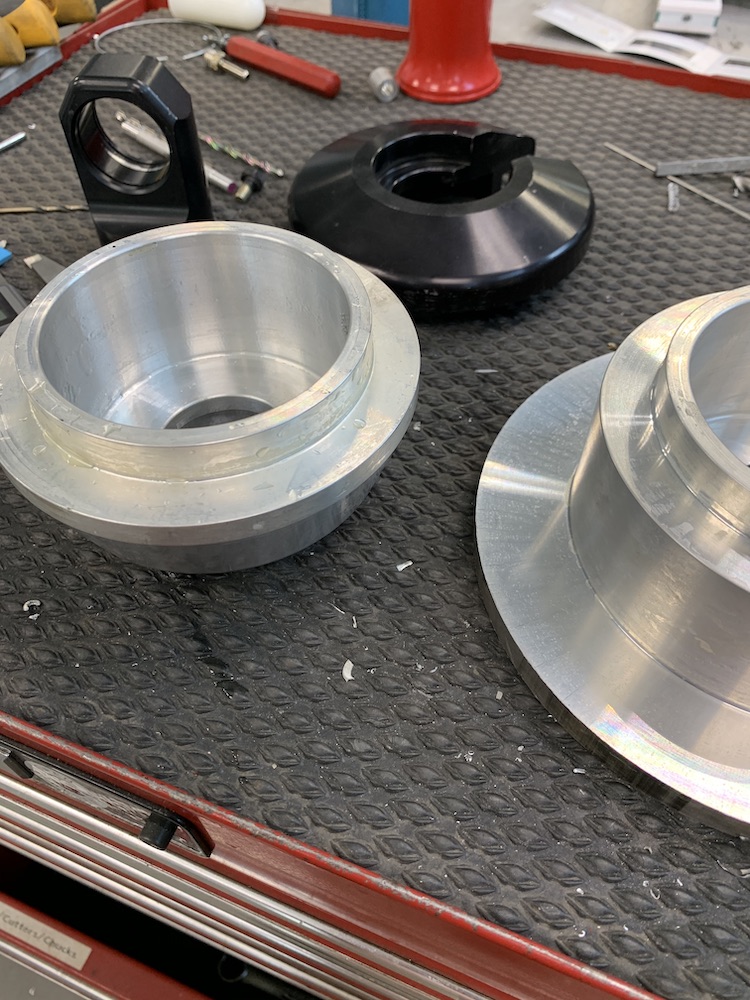
Here's that far right piece, finished along with another friend that gets finished the correct way also.
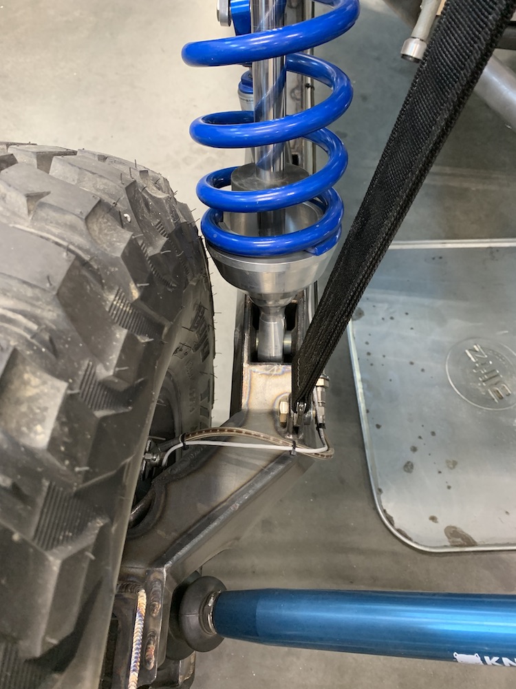
New spring perch in place. Pic doesn't quite show the additional clearance I gained. I'm also going to offset the shock spacers .125" - .150" so the shock moves inward and away. Should give me about 1/4" clearance at full droop. Tires will still hit stuff - the sidewalls flex, but it shouldn't be an issue.
At ride height the clearance is well over a half inch.
More later, as always.
Apr 10, 2020
Finished the spring cups. They have clearance everywhere needed. Still, it was tighter than I want so a bit more room was needed to be found.
A bit of shock spacer mods gave me another .175"
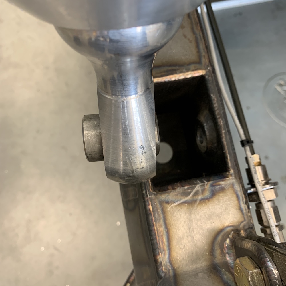
And, much to my surprise ('cause nothing works on the first try) no hitting, no bumping, no interference. Just clearance!


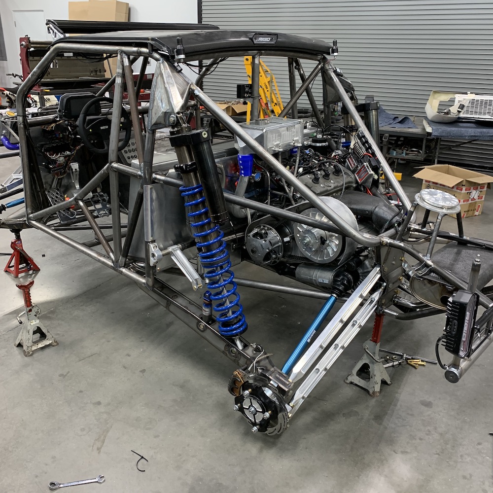
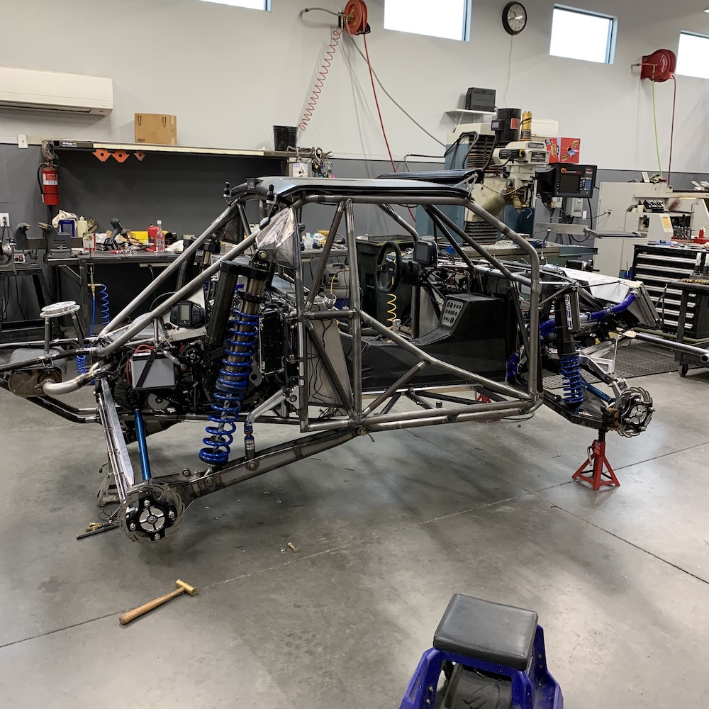
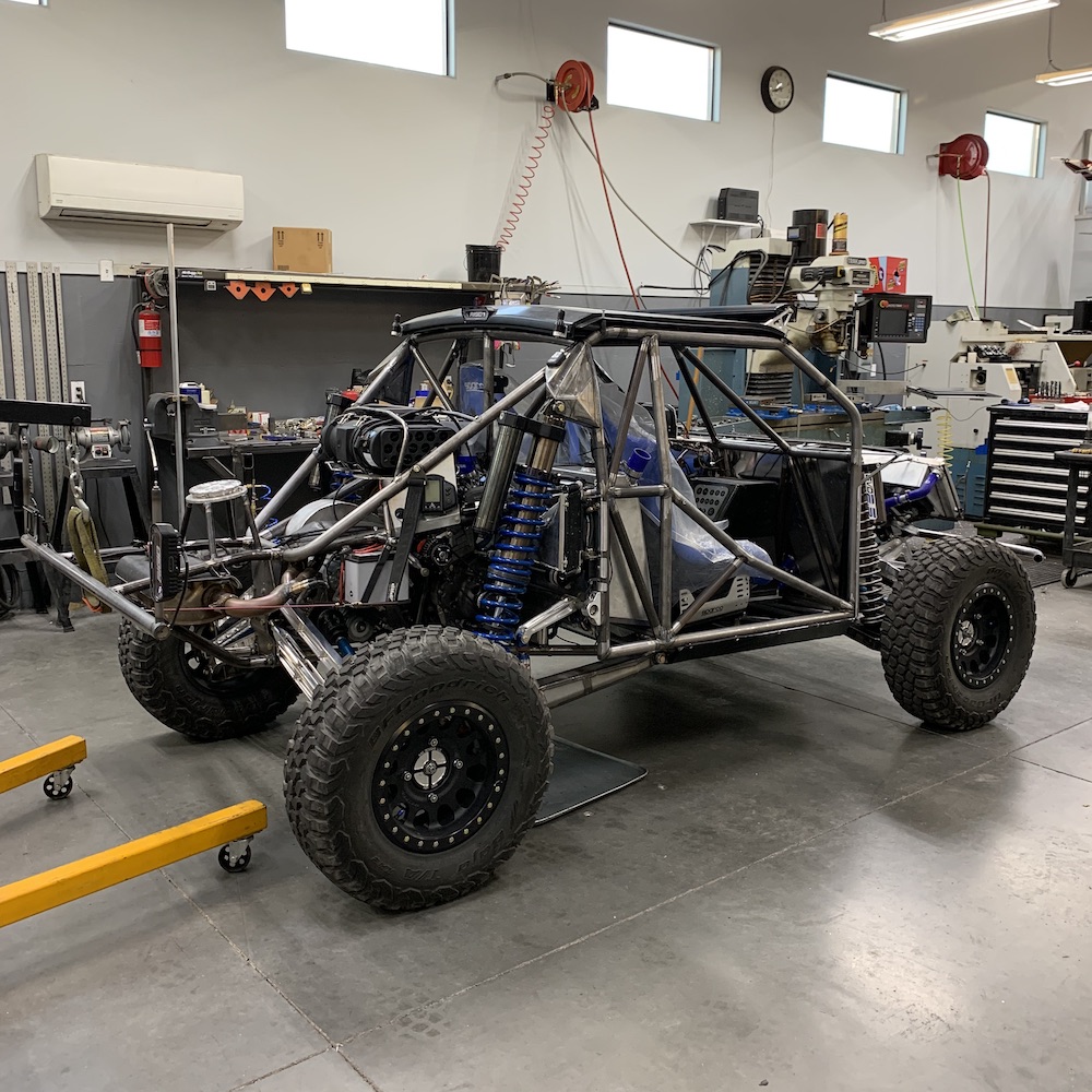
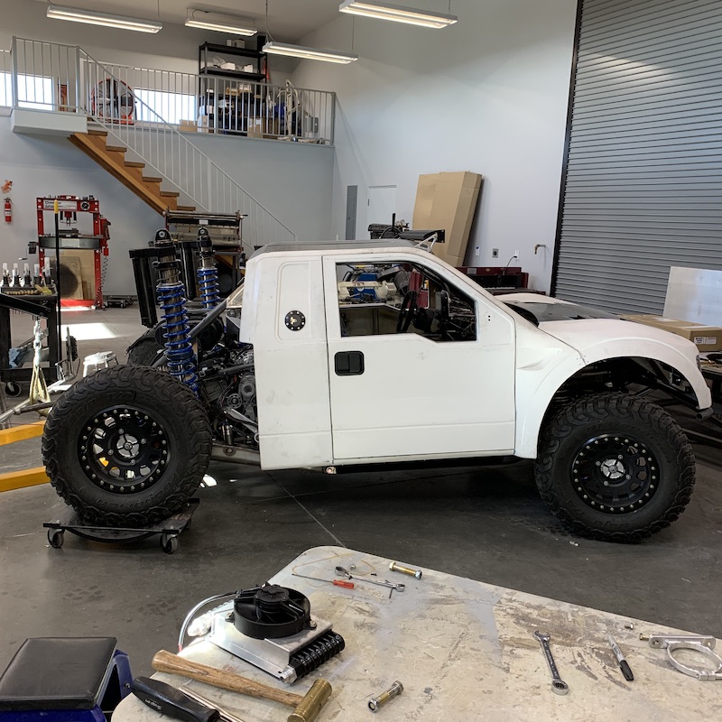
Gratuitous chassis shot.
Apr 20, 2020
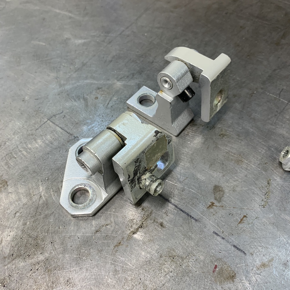
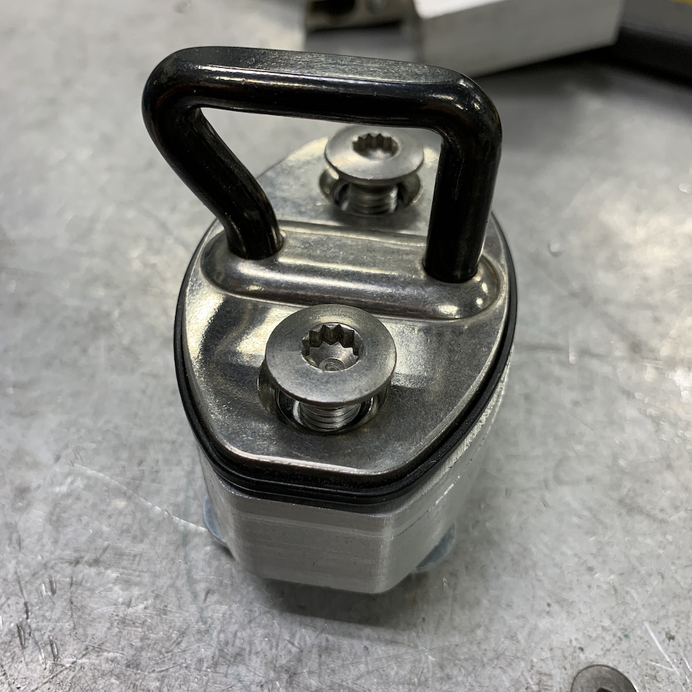
Benihana supplied Audi A4 hinges and Audi R8 door latches with the Mini-Raptor body.
Not sure why I only have one latch in my box o' door stuff that came with the body. Can't find the other latch so the second one's on order and should be here this week.
So door installation began.
Driver's door was already drilled for the hinges (thank you Beni!) so I put the hinges in, played around with fitment (very nicely done Ben!) and then tightened them down.
Audi A4 (various years) hinges:
Upper hinge:
Lower hinge:
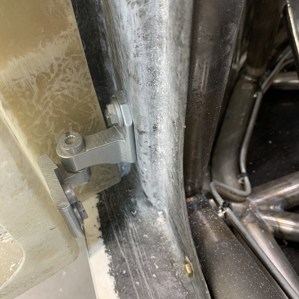
Door swinging in the breeze:
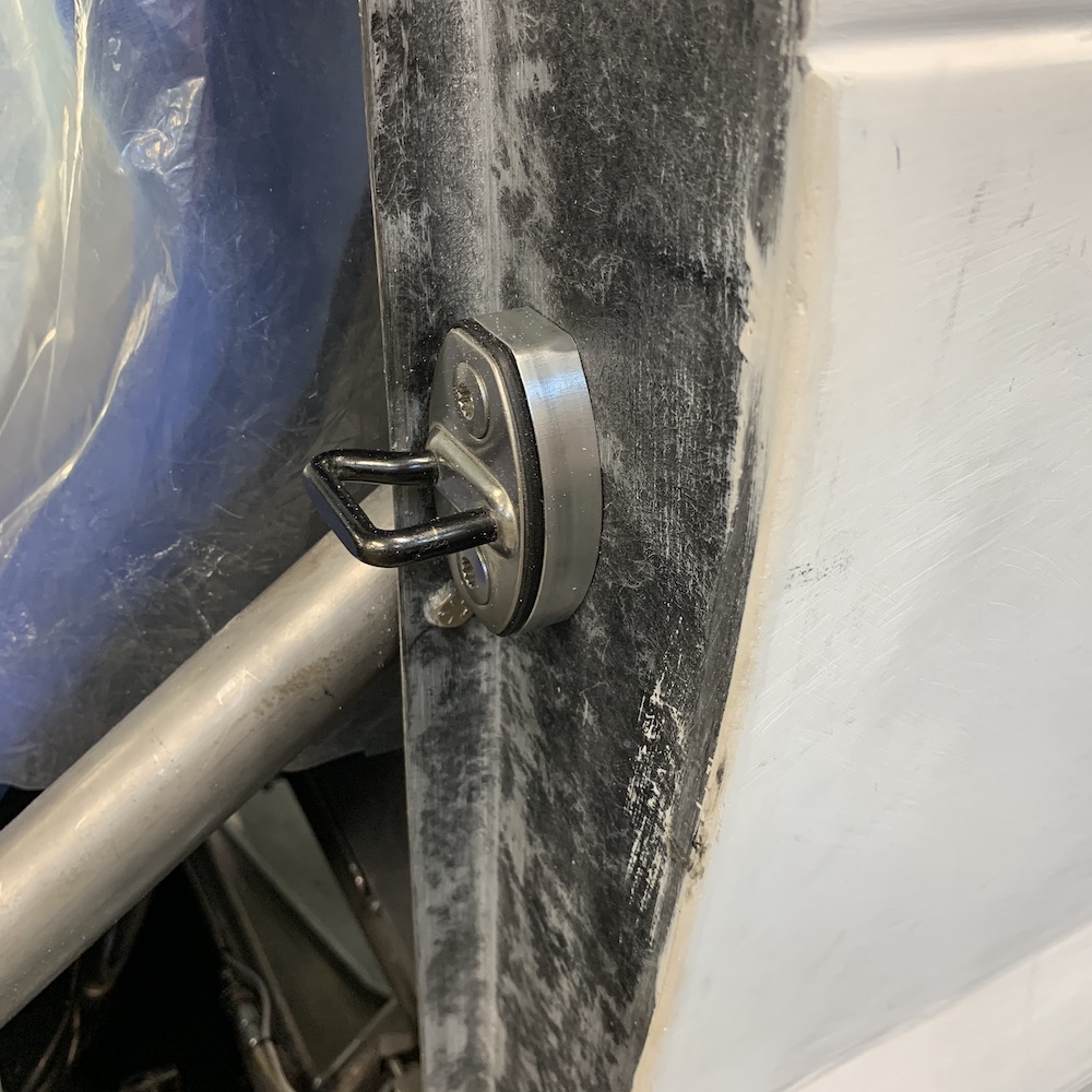
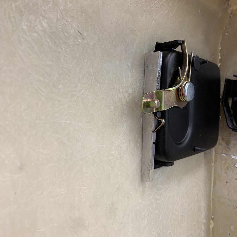
Once I got the door swinging without interference it was latch time. First thing was to locate it:
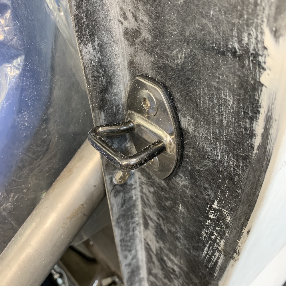
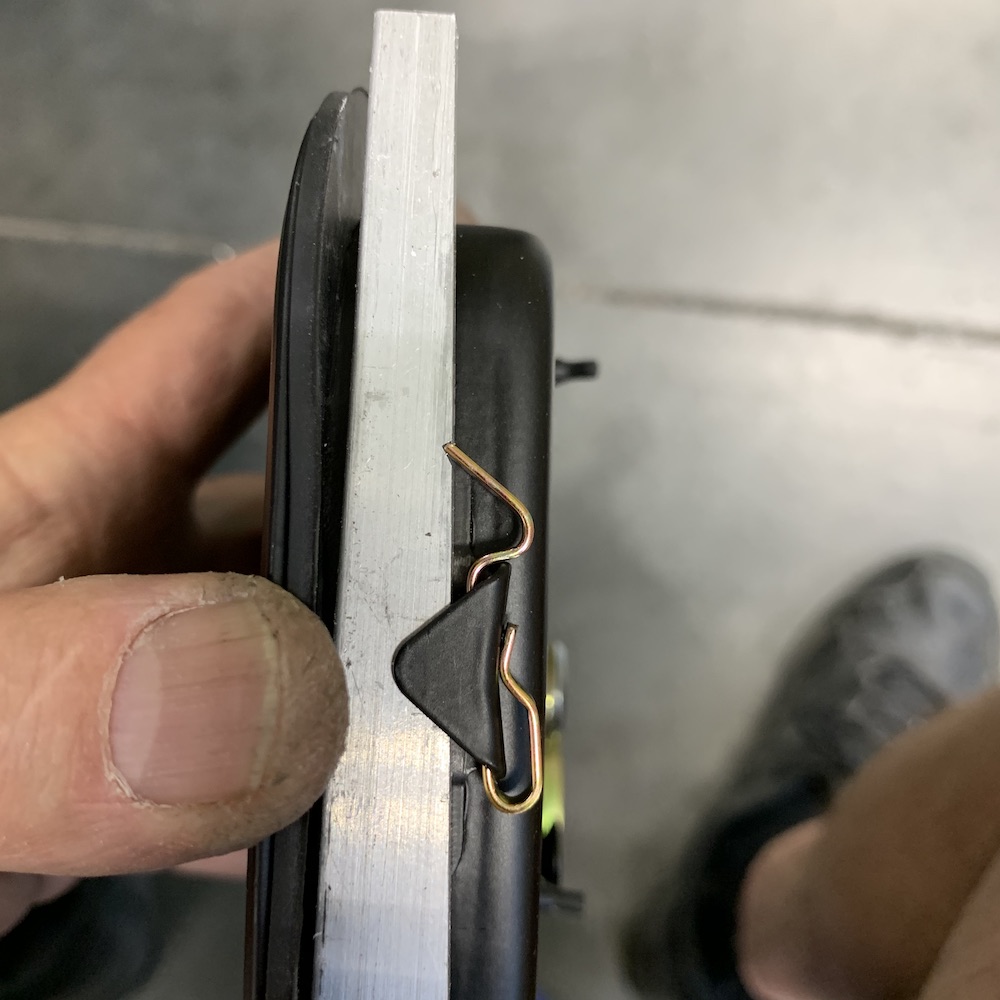
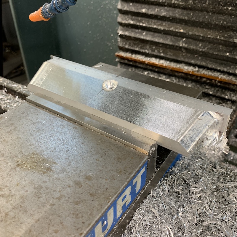
The catch needed to be space about .700" off of the door sill so I would be able to capture it with the latch. That required spacers to be made. The catch is held on with two 8mm countersunk bolts and the spacer is held in from the other side by four 1/4-20 bolts:

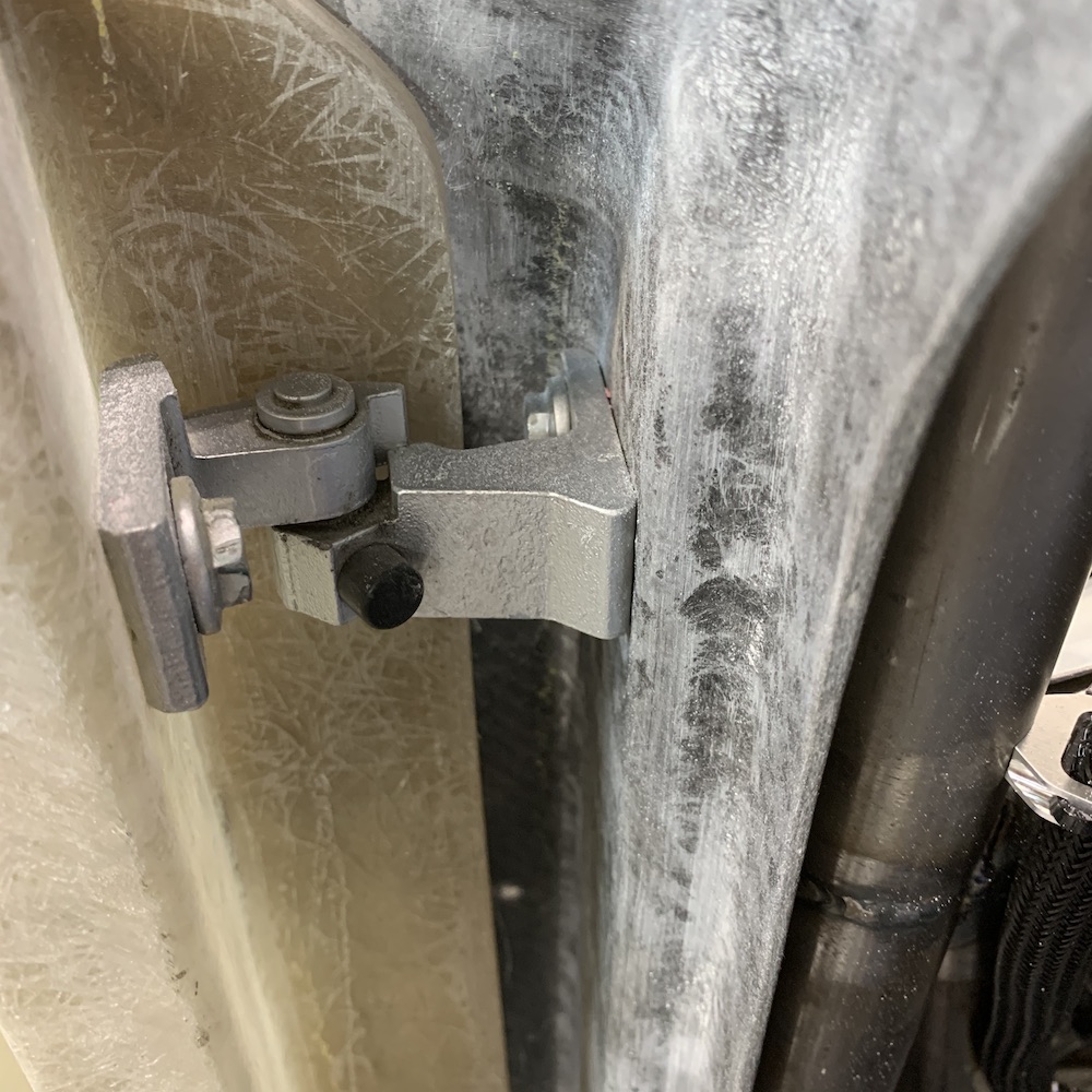
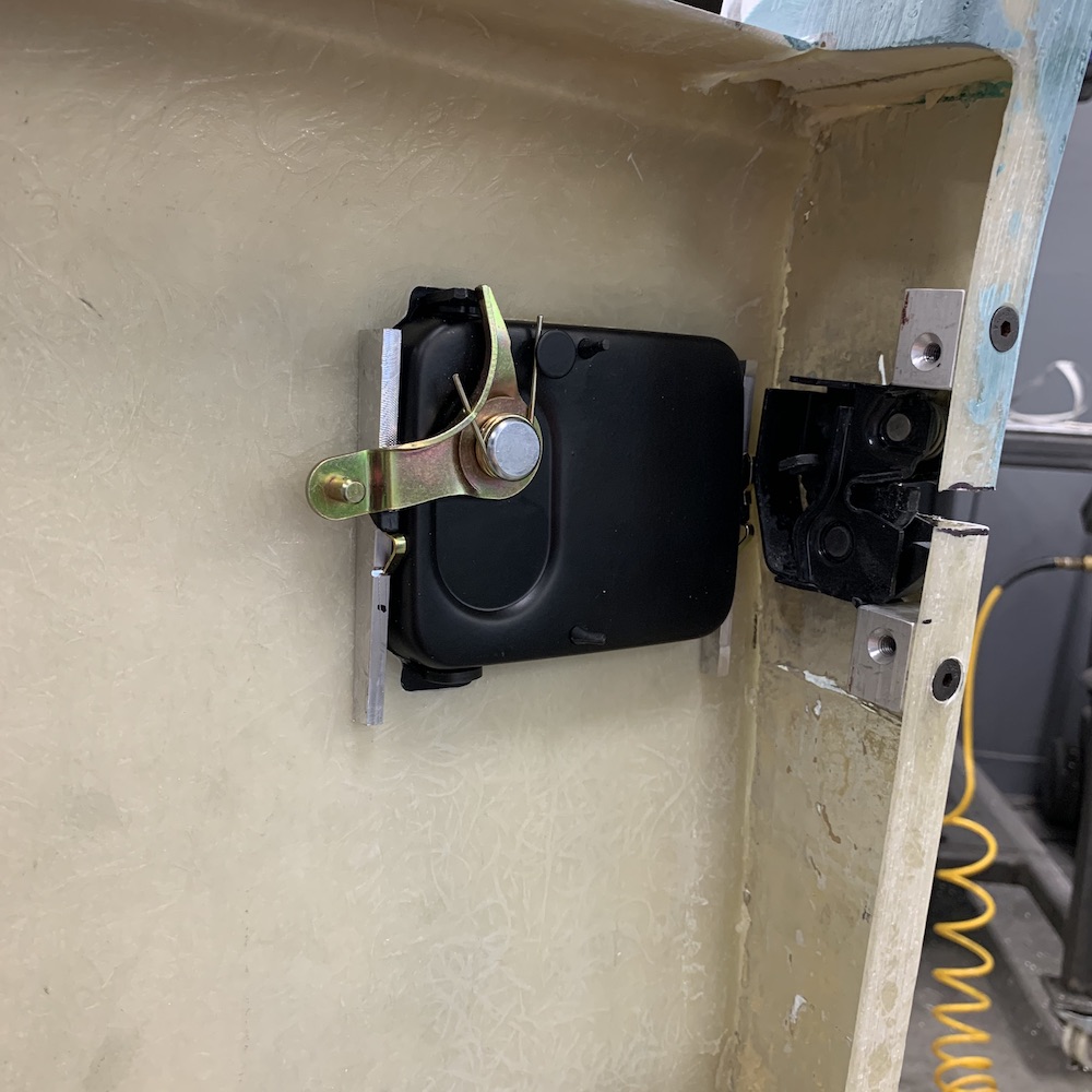
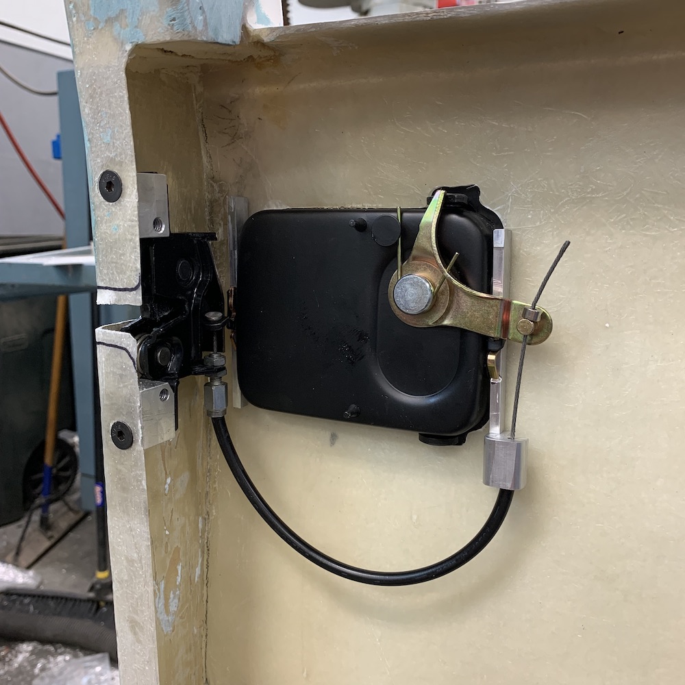
Once I got the catch located and mounted it was time to install the latch. It fits nicely against the door sill, grabs the catch very nicely and needed a couple of mounts to hold it in location.
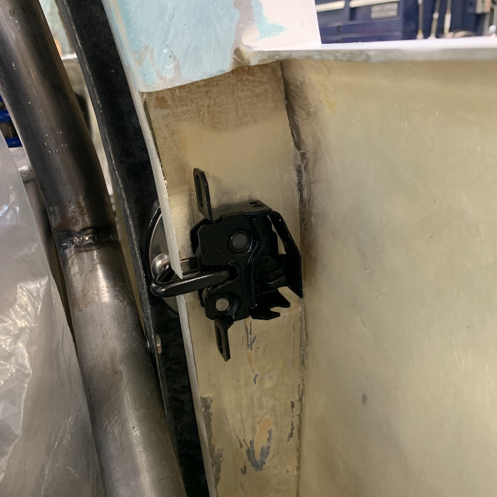
Mounts installed, latch attached:
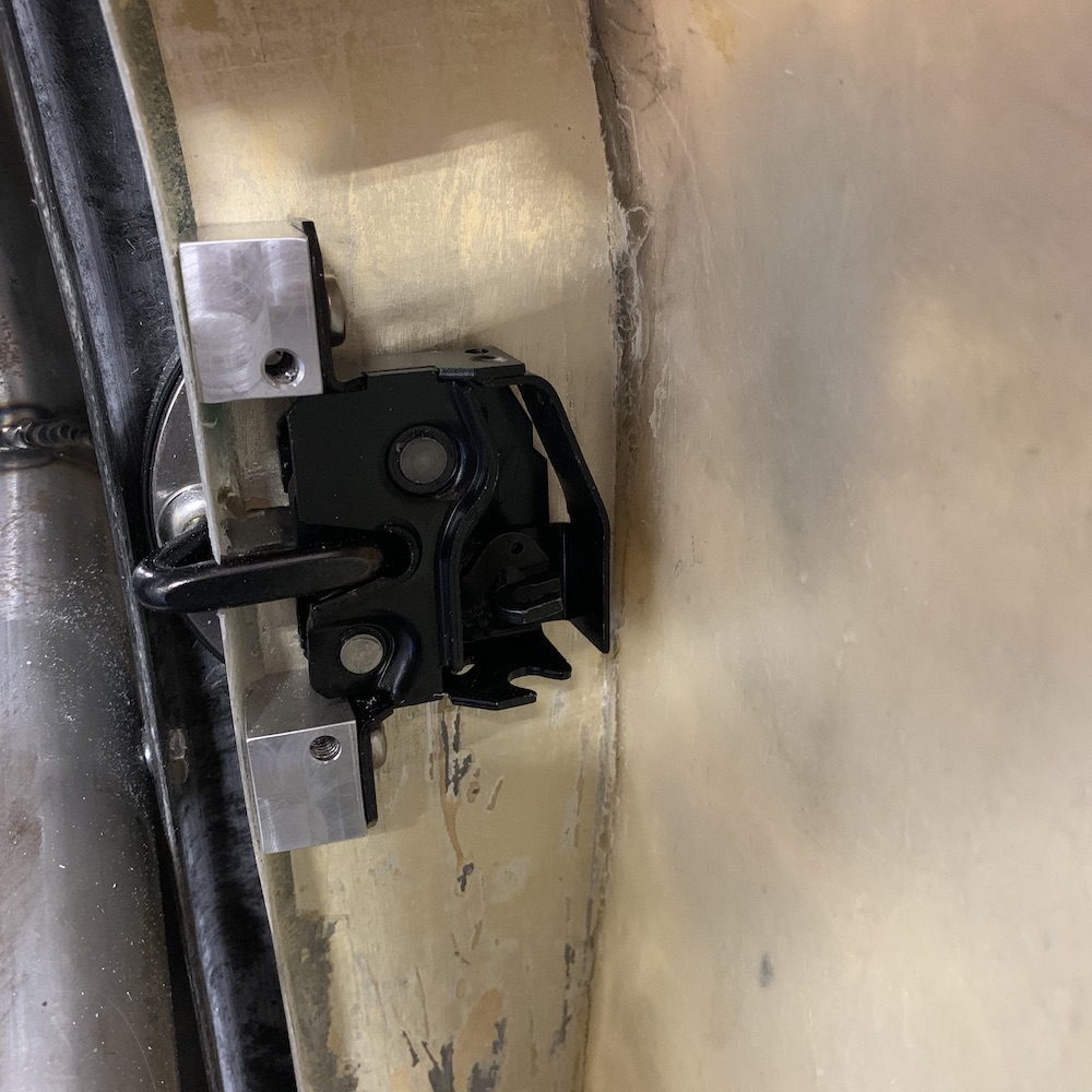
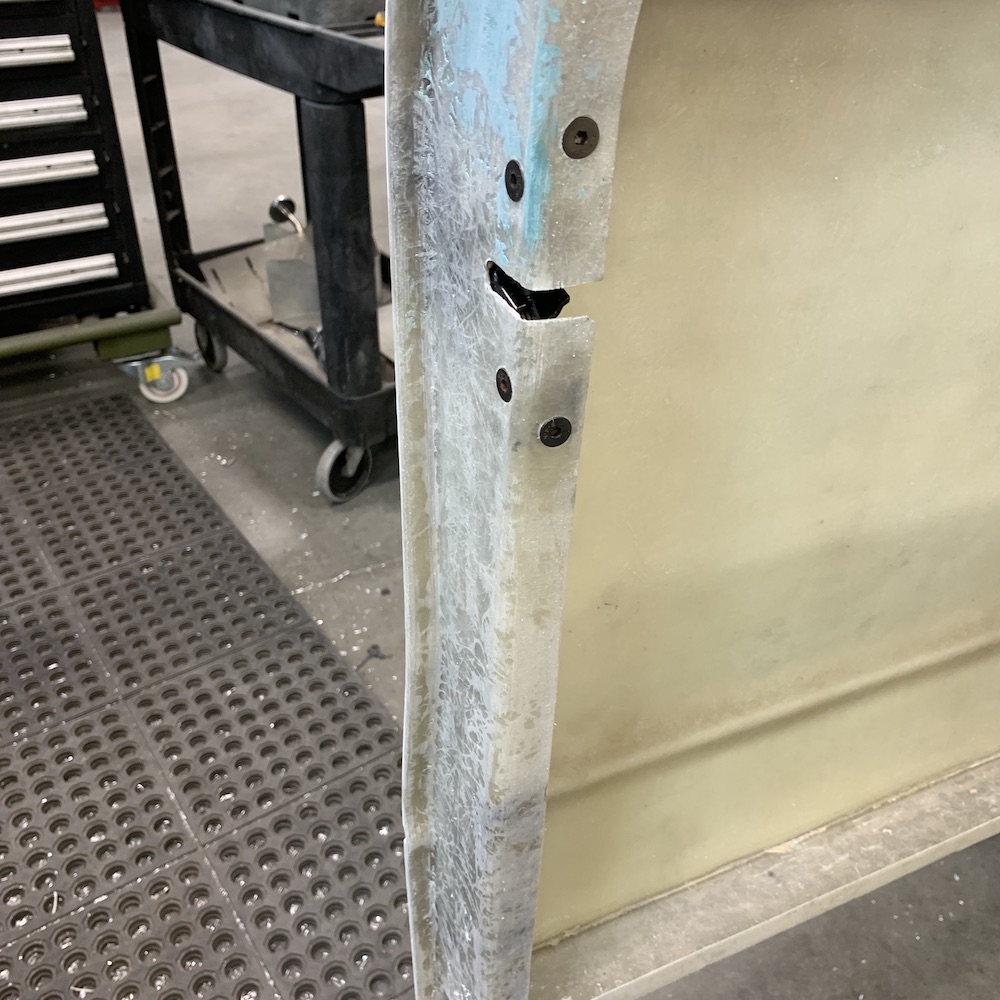
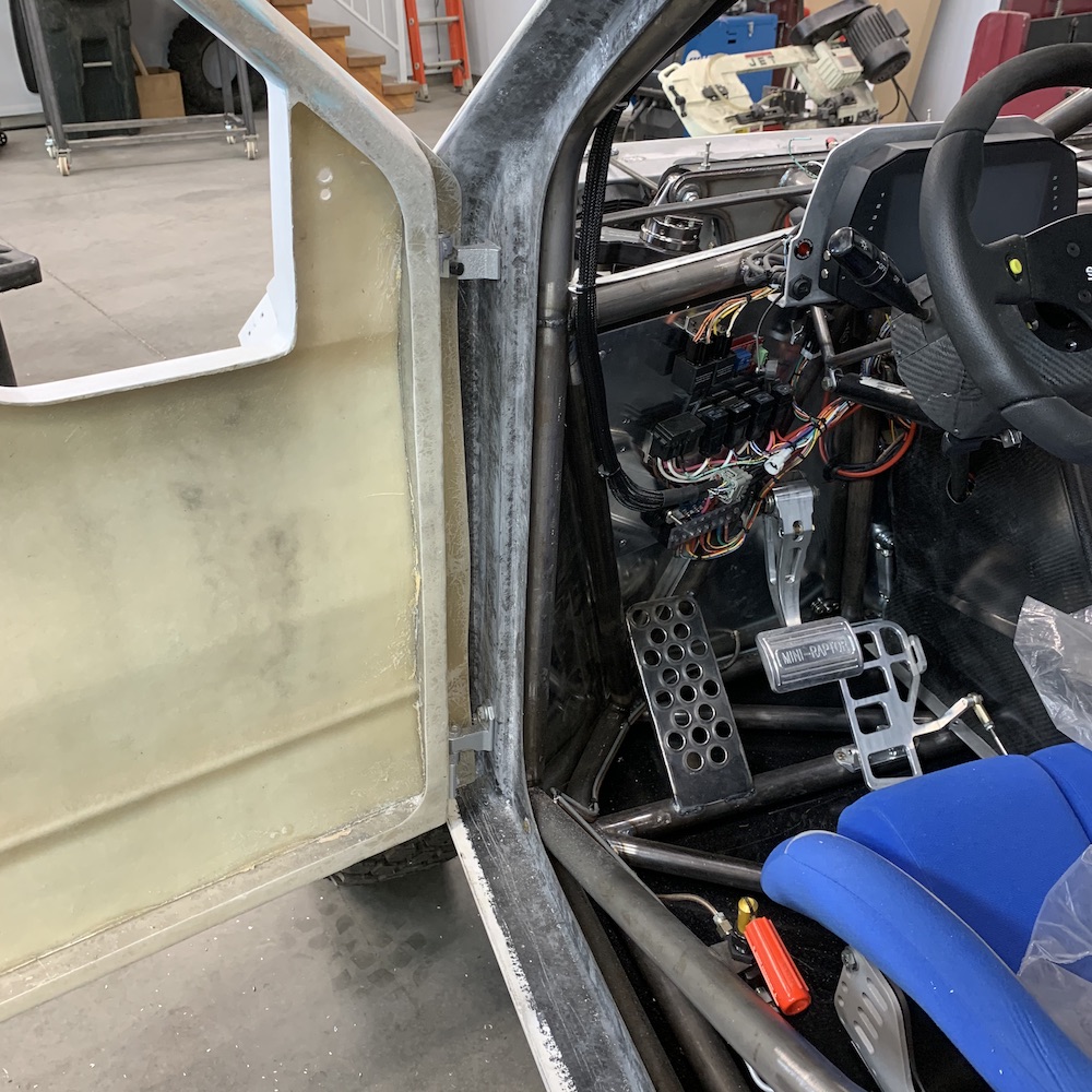
Door installed and latched shut:

I spent a couple of hours getting the passenger's side door hinges all lined up and mounted (was easier than I was expecting).
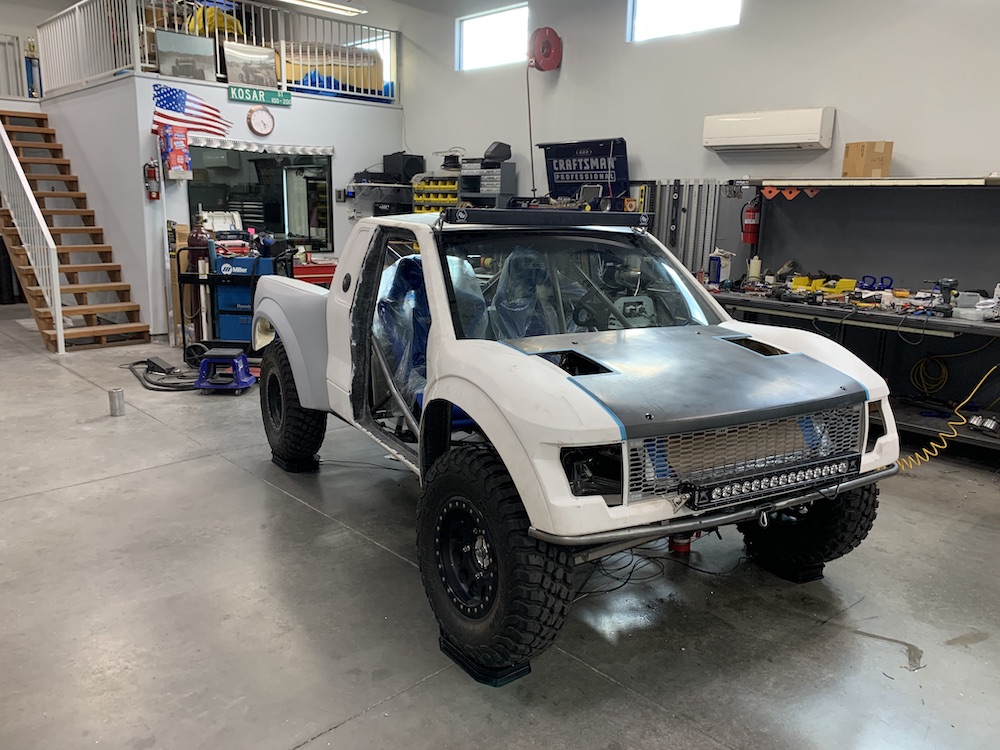
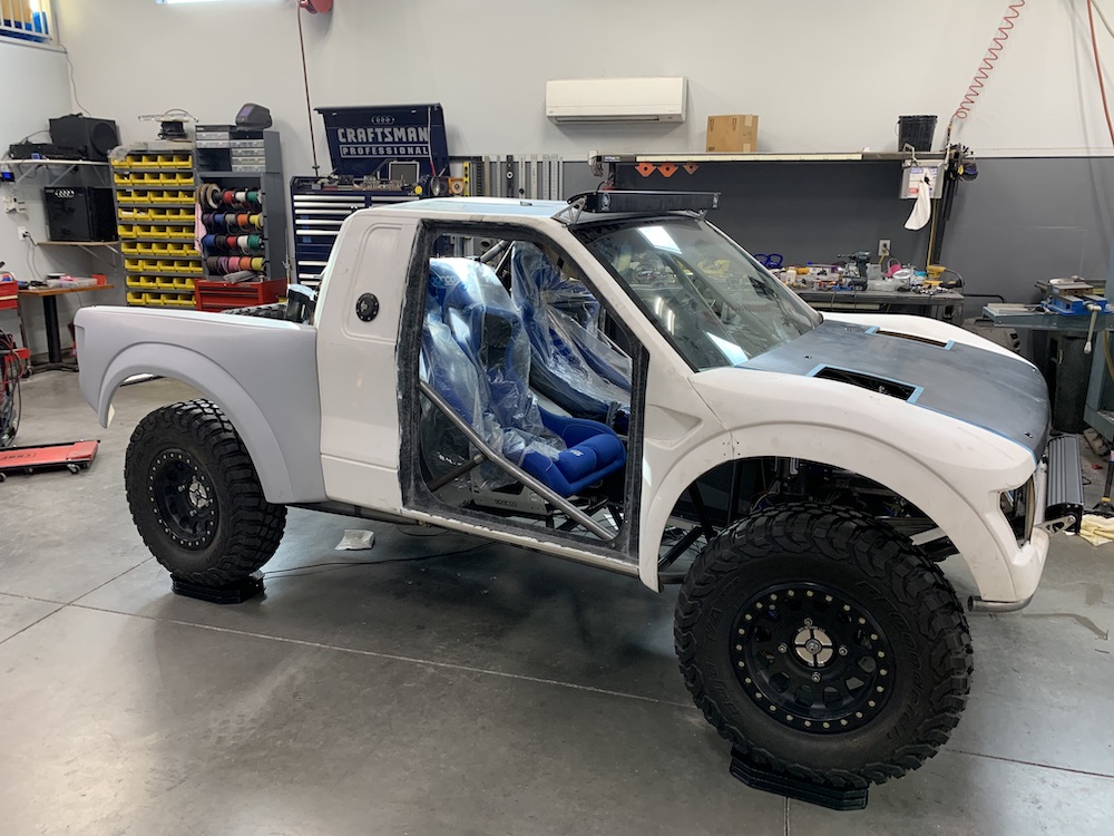
Of course I had to throw the hood on and see what she's gonna look like with all her clothes on.
I have to go source some cable now - something like bicycle brake cable - to operate the latches. They and the door handles (gonna install today I hope) are all cable actuated.
I got Jeep door handles for the outside, still clueless what I'll be doing for the inside handles. Heck, I'm not even quite sure how the darned Jeep handles mount. There are a couple little ears with some sort of locking key/wire/thingies on them. I need to go explore the internet and see how Jeep does it.
Still waiting on my supercharger. Contacted the company and said 2-3 weeks has turned into 3 months. If I can't get it back, repaired, by the end of the month, just send it back and I'll see about screwing it up more on my own.
Apr 23, 2020
Okay, lots of pix. Been busy doing little picky shit whilst I WAIT ON MY DAMN SUPERCHARGER!!!
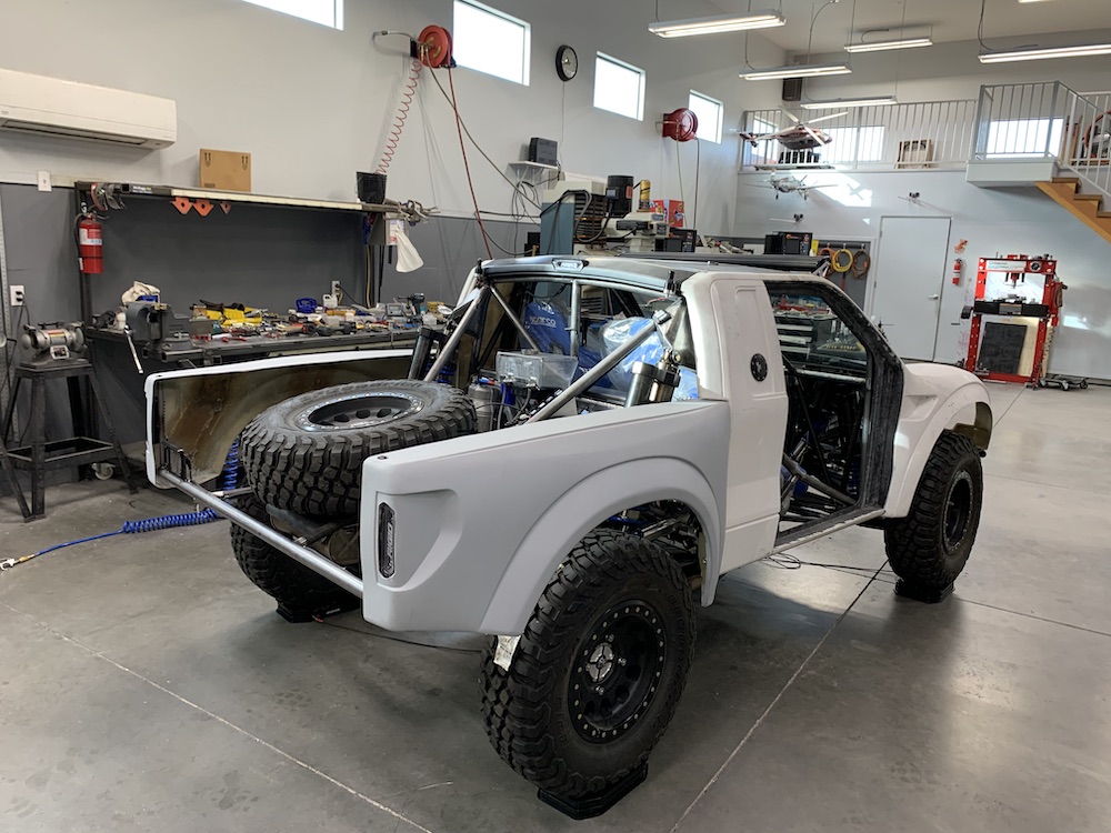
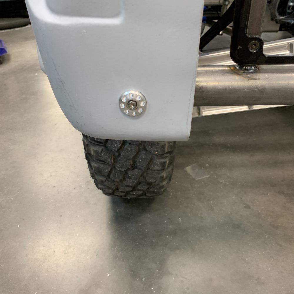
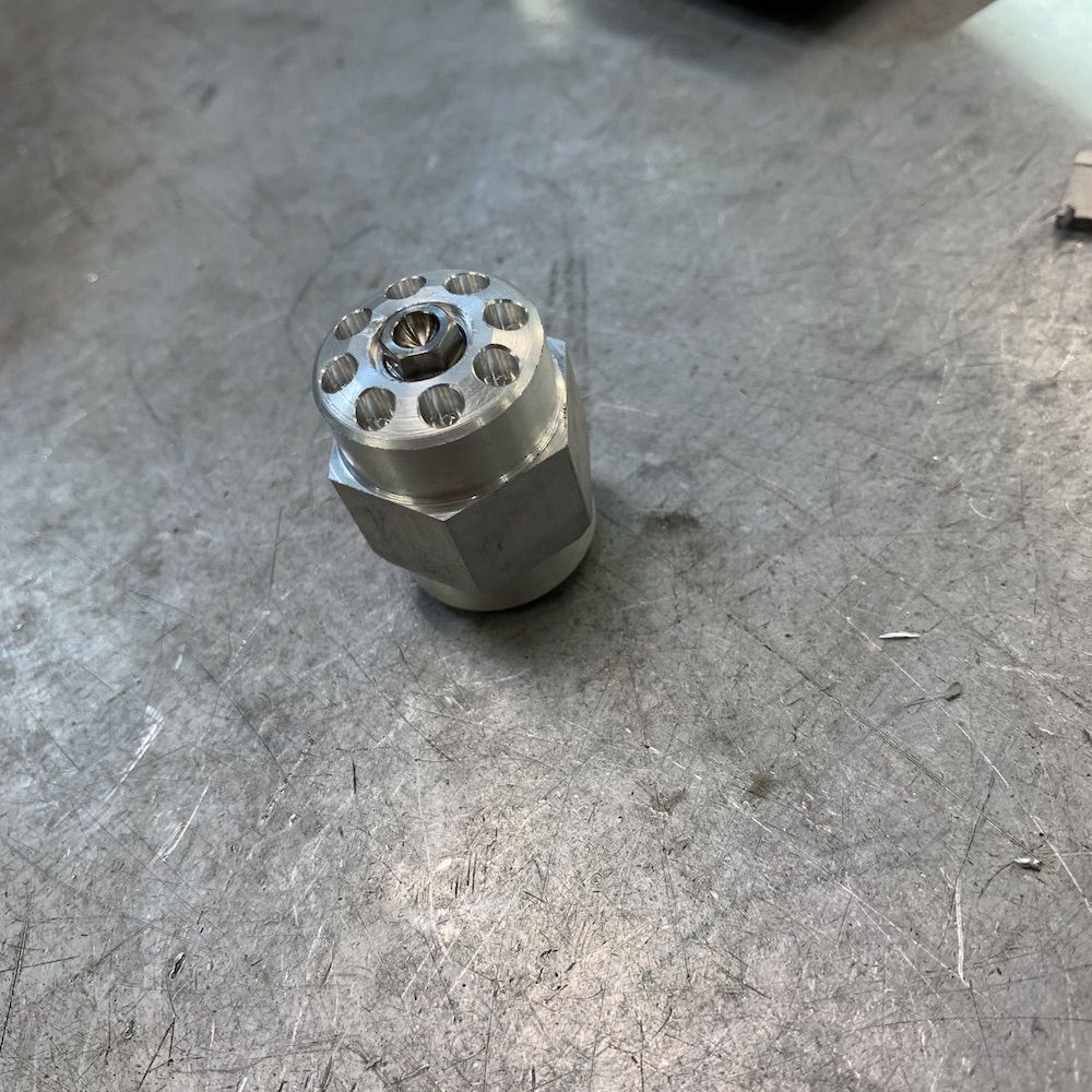
Years ago (like mid 80's) I got to be around Factory Honda racing stuff. They always had these absolutely beautiful light weight washers holding bodywork on (saw them on both the factory Superbikes and MX bikes - so someone in house was knocking them out) and I've always admired them.
So now I have Factory K-fab washers holding the lower ends of the bed sides in place. Had to make a brackets that bolted to the end of the rear bumper (fortunately I'd already put end caps with a 1/4-20 hole in the middle on the ends of the bumper tube).
They even have titanium fasteners for that factory effect. (I've had three bolts and four nuts (guessing one of the bolts "bolted" - yeah, I know, that's bad. I had to.) in a box for 15 years waiting on something like this.)
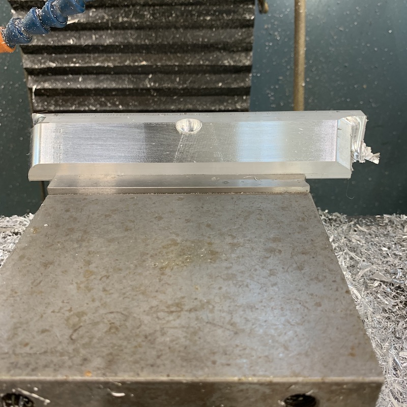
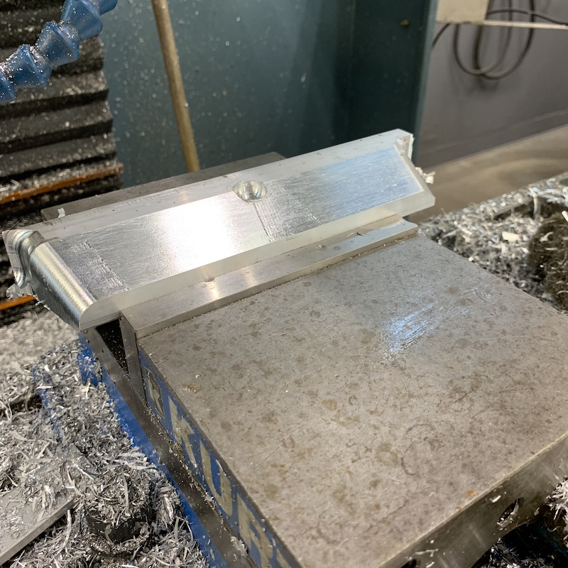
Washers in progress - turned the main body and the tapers and then milled the pockets.
Bracket and washer getting ready to do their thing:

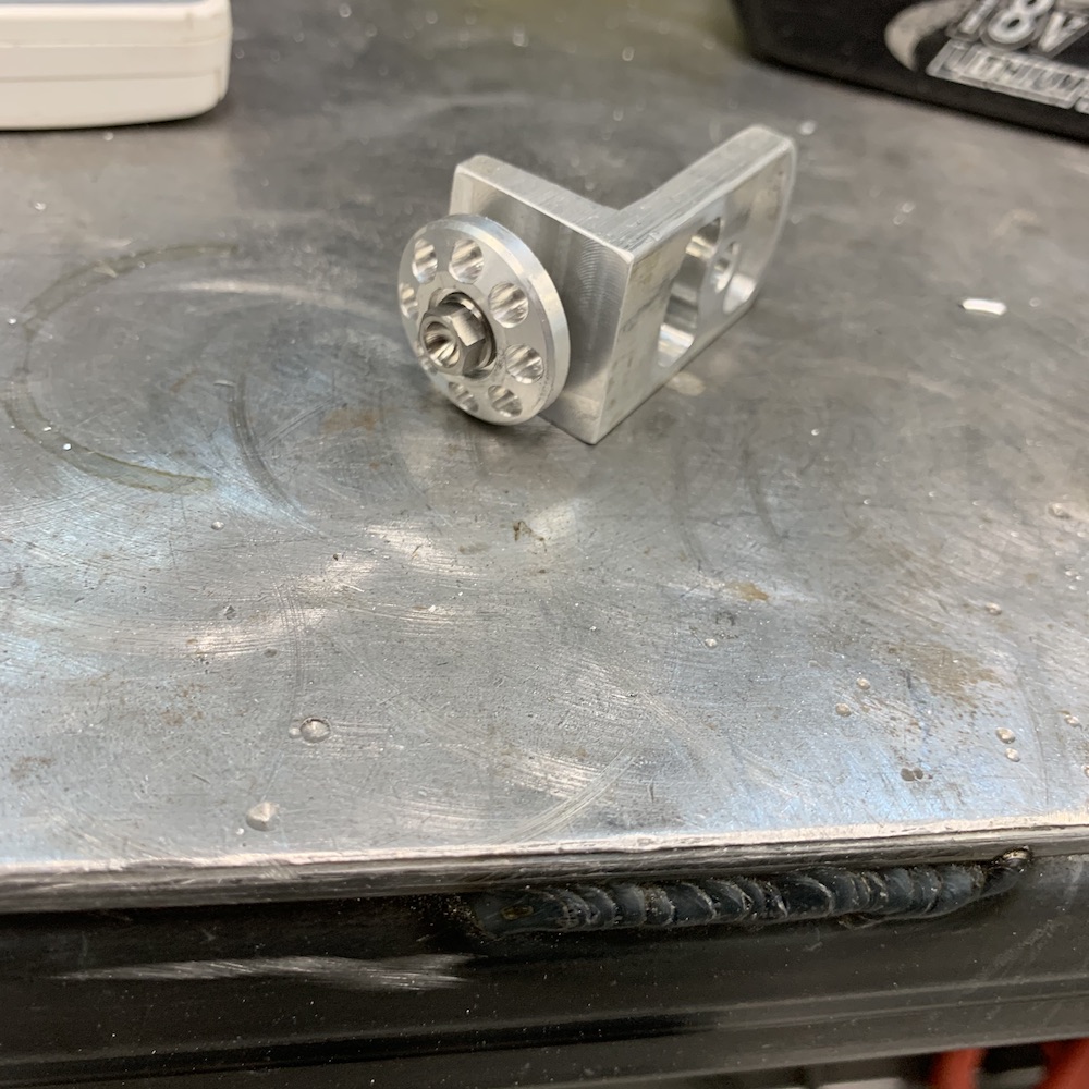
Bracket installed on end of bumper tube and against rear bed side back lower end (wonder if I can get anymore words of location into this sentence?):

I also got the outer door handles (Jeep) installed and the driver's side operational (still waiting on passenger's side catch to show up - tracking says it'll be here today).
Cutting fiberglass is so much fun! (ITCHY!!!)
The Jeep door handles are held in with wedges and a little key that locks the wedges in place:
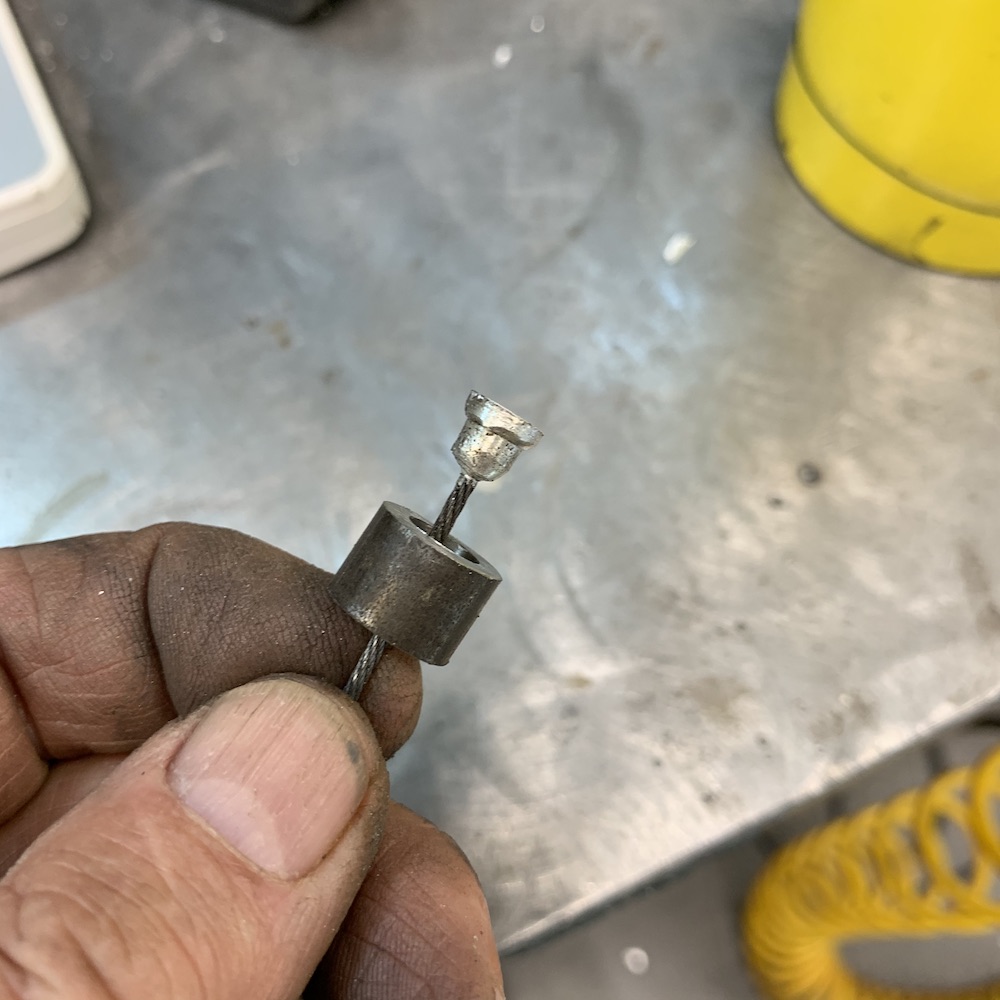
Once I got the handles in I had to figure out how to make stuff work - all cable actuated so I pulled up a post I saw on the MBN Facebook page on how to make cable ends. Knocked out a little mold and tada, custom cable ends that fit in the latch mechanism PERFECTLY (whew!)
Only took three tries - first mold wasn't tapered and the inner surface wasn't smooth (drilled) so I couldn't get the end out. Two messed up ends with that piece.
Second mold has 4 degrees of taper and the inner surface is very smooth - the end pops out with minimal fight.
Had to make a couple cable stays too. They bolt onto one of the door handle mounting wedges and direct the cable towards the door actuation lever.


Working door latch system! WOO HOO!!!
Next I get to figure out how to put an inner door handle on - not sure where it'll attach to activate the latch. Heck, I'm not even sure where the darned thing's gonna be. There'll be quite a bit more happening inside the doors so I'll get to the handles soon enough.
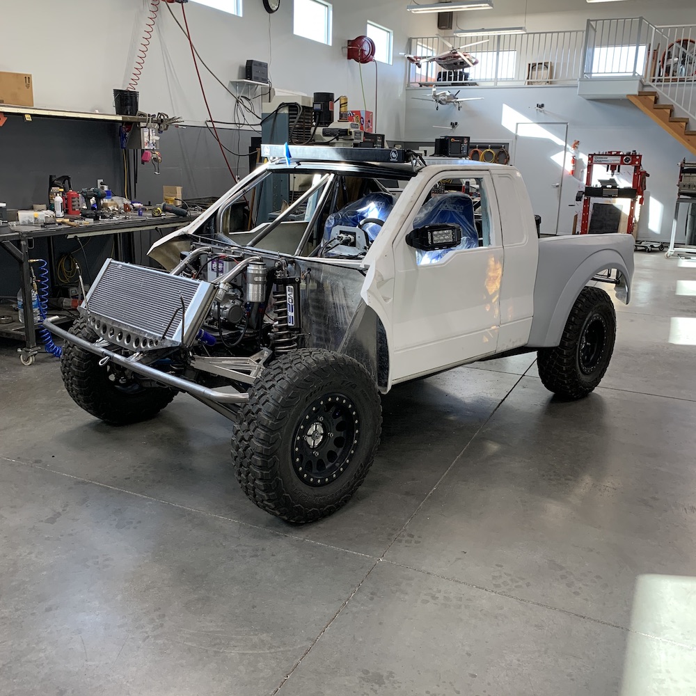
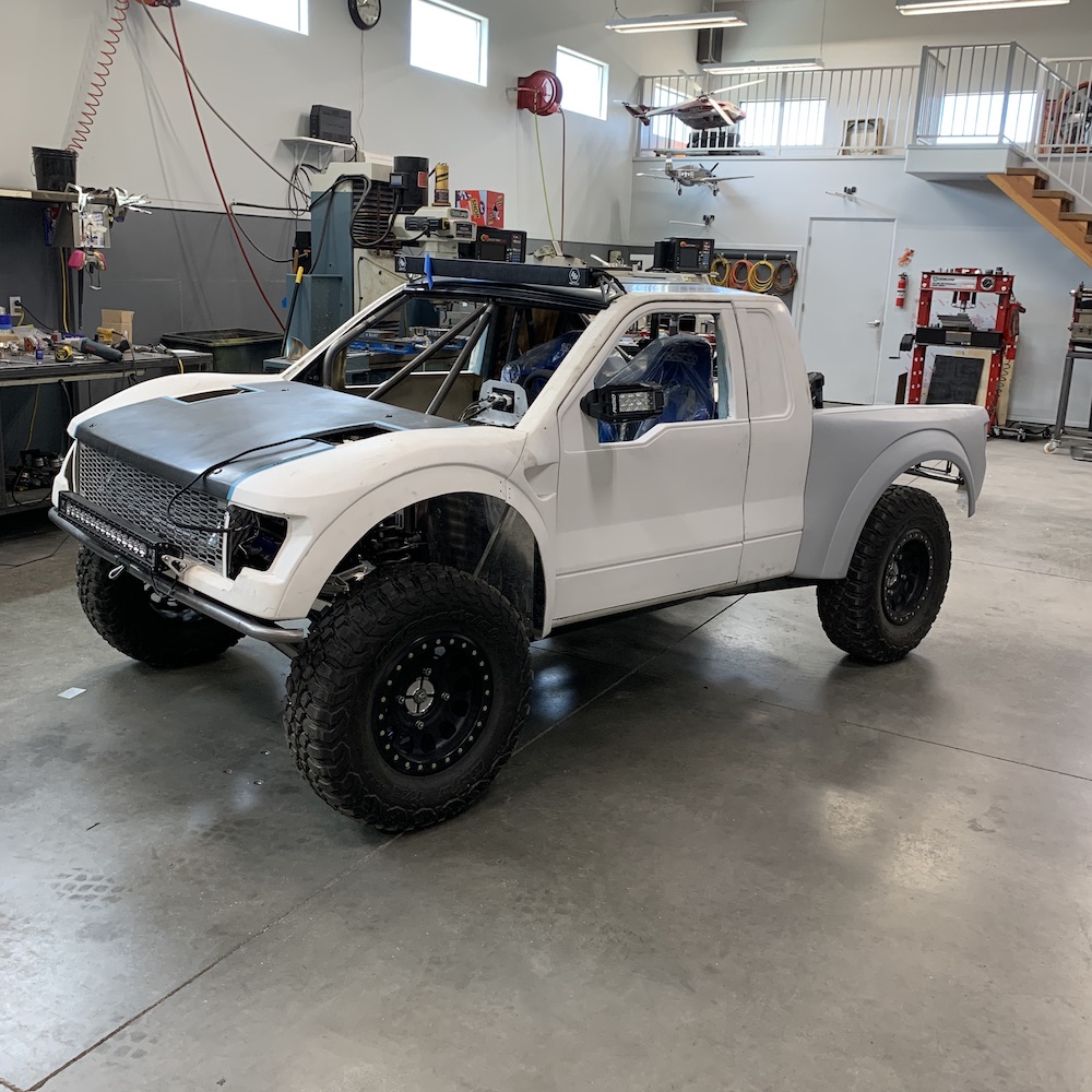
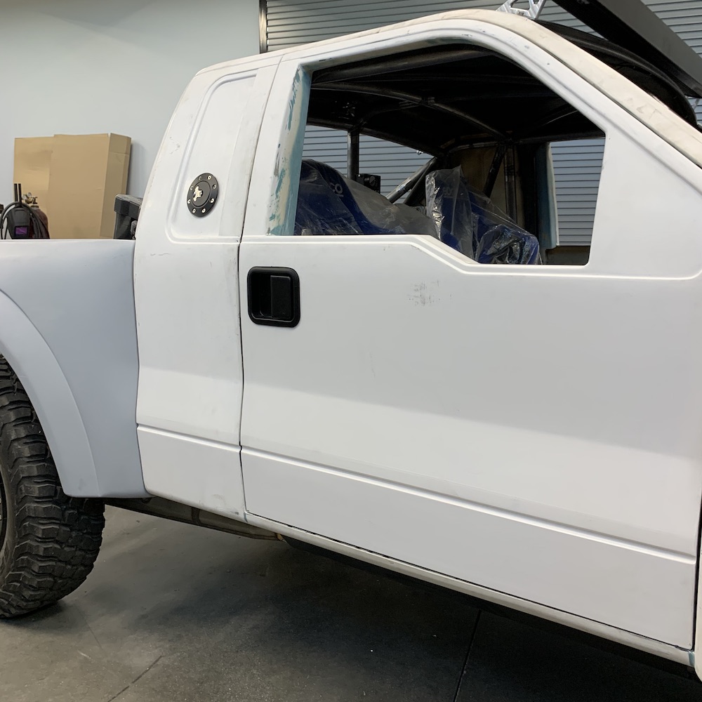
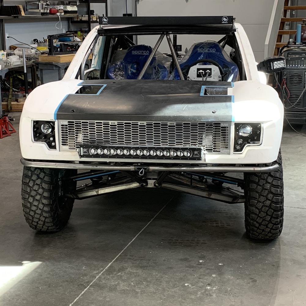
Gratuitous Mini-Raptor shots - it's starting to look serious.
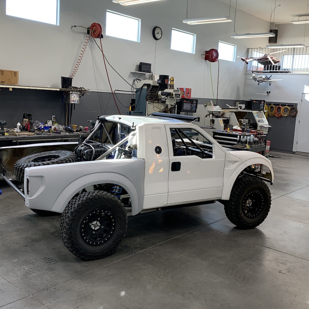
Honey, I shrunk the Trophy Truck!

Apr 24, 2020
Moving onto the hood and the electronics in it.
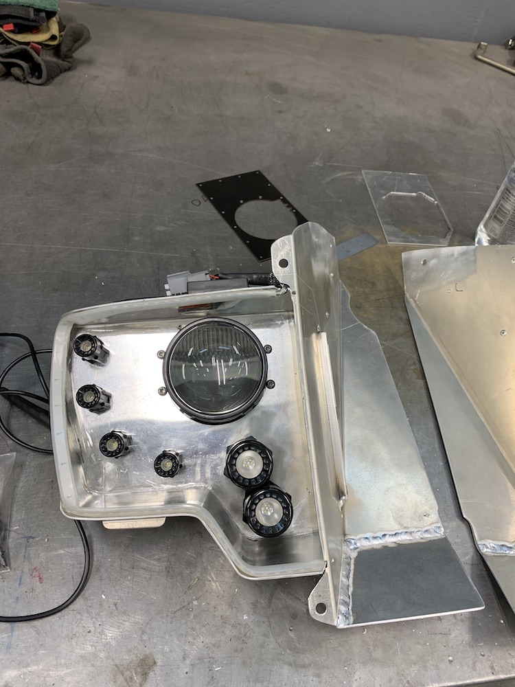
The main headlights kicked my arse the first time around. They come with no instructions, they have logos on/in them that seem to be counter intuitive (one's inverted) and there's no indication of "this side up".
Of course I put this side up down... Why wouldn't I? I've only built 1.5 Mini-Raptors thus far (only kept 1, the other .5 has headed to the scrap bin).
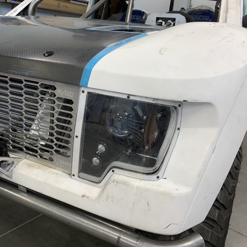
I also didn't like the position of the lights. They were too far inward. And, I wasn't really that stoked about the shiny aluminum back of the light assembly. Time for a change.
Decided to take a bit of an industrial look on the redo.
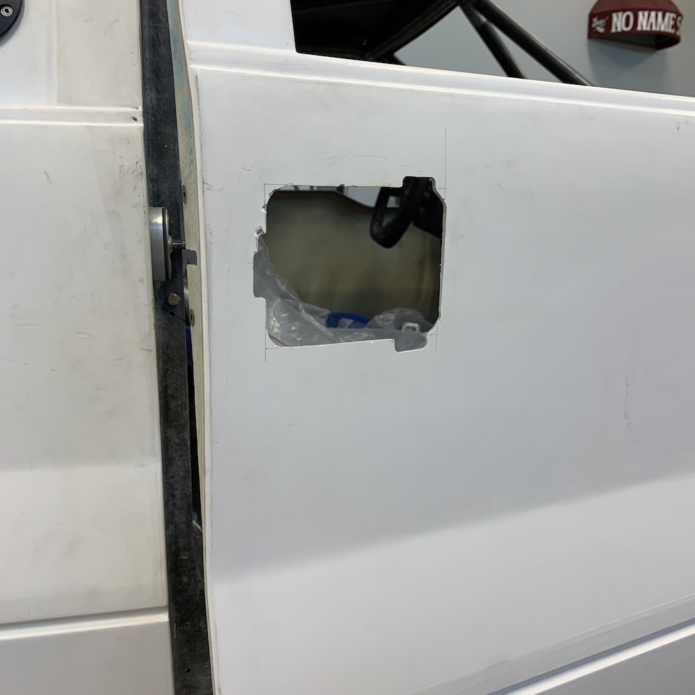
I'm not about to try to remake the whole light housing box. That was a week of headache, swearing and sweating. Instead I cut the area out where the main lights were and then relocated and inverted (to the correct orientation) them. Cut a small panel, made the edges kinda sharp, little socket head cap screws, some paint and tada, new, much better looking headlights.
Gotta finish the passenger's today. Have most of the stuff already made - just need to cut a window, drill a few holes and paint the housing.
Also got my other door latch so I'll knock out a cable (everything else is ready to bolt in) and be done. I'd say 5 minutes but that'll automatically make it a 1 hour job.
Headlight how I left it after making it. Main lens is too far inward. You can see the new mounting plate and the pattern plate in the background:
Headlight after mods:
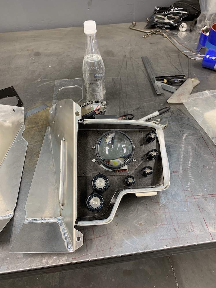
Comparison of the two:

Looks so much better with some color.
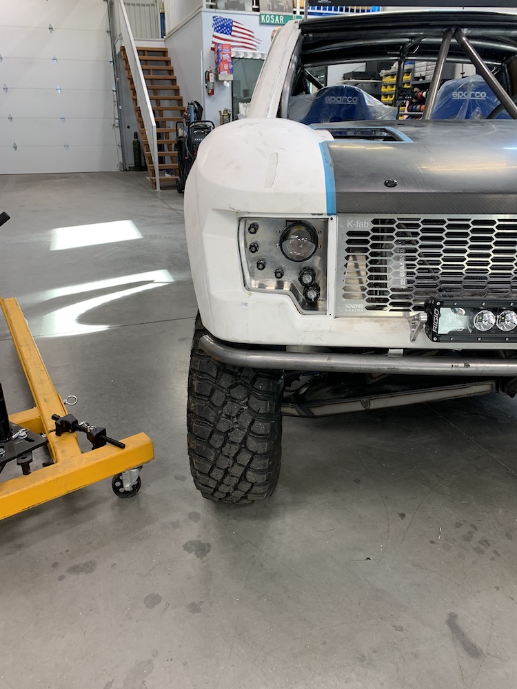
Apr 29, 2020
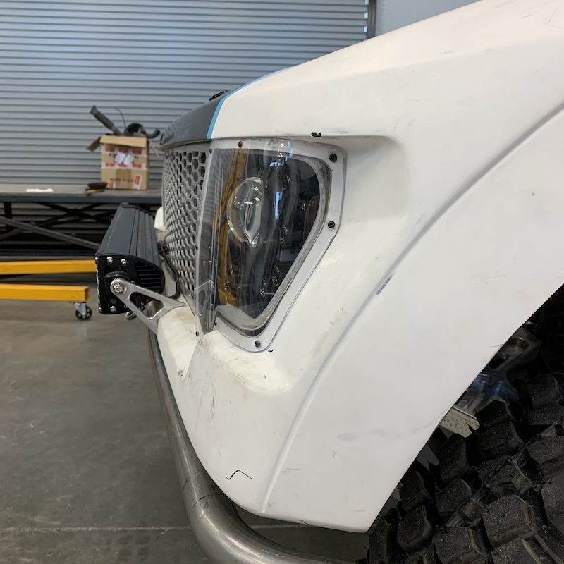
Headlight assemblies are finished. Still have to make the Lexan covers of which I have a prototype started.
The headlight electronics and housing are open to the world so I figured an FOD shield would probably be beneficial.

Side shot of the shield - shows the stuff it's protecting:
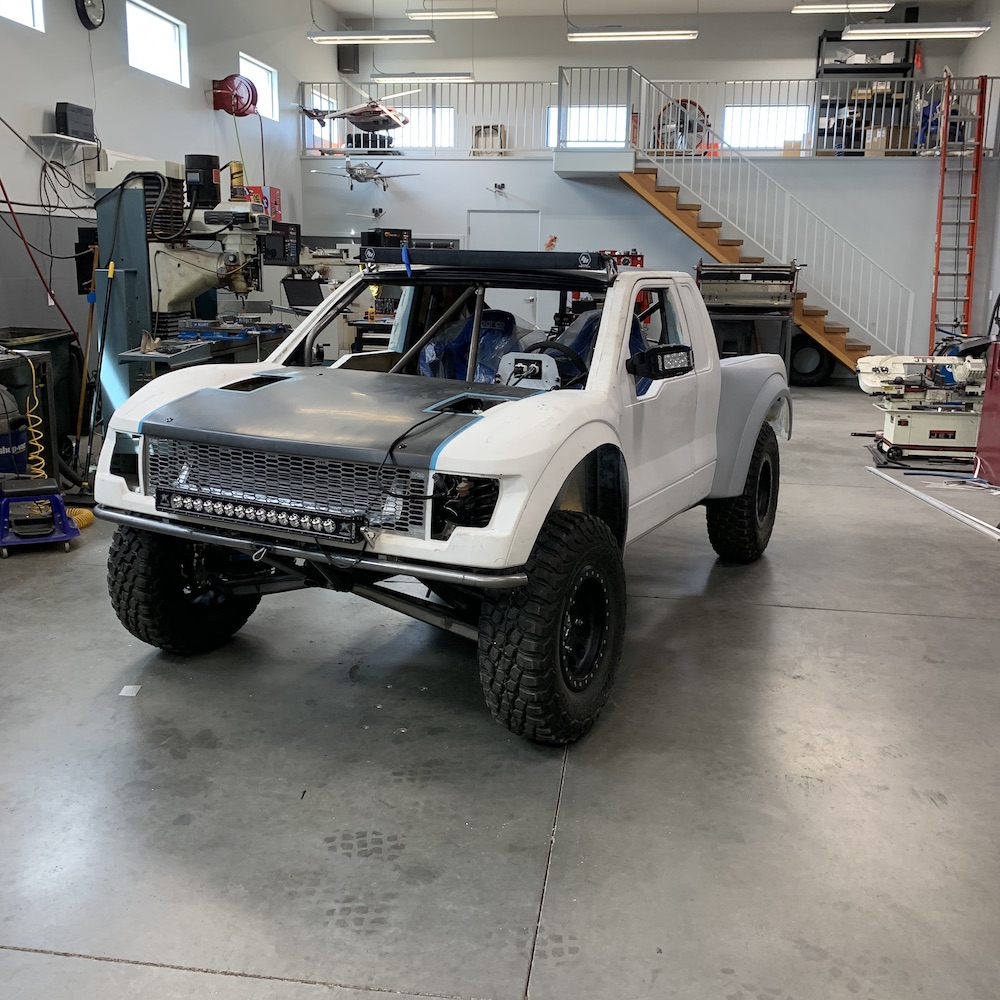
Installed headlight assembly:
Looks SO much better with the revamped & colored headlights, don't ya think?
May 2, 2020
Headlights installed and covered with Lexan.
The two LED lights on the bottom are BRIGHT - like not gonna be able to use on the street bright.
Prototyping hood vent louvers now.
Ignore the 5/8" hole - one little line in the code and the machine makes a grunt and punches a hole. It's all good - this IS a prototype (and that line of code is gone now.)
Tried two profiles - regular old radius, kinda "standard" louver shape and then tried a chamfered transition for a little more interest. I think I'll be going with the chamfered look.
First test run, getting the taper correct:

Radius on left, chamfer on right:
Radius close up:
Chamfer closeup:
Called it a day after it plunged the cutter into the piece so I didn't get the whole program run.
Planning on these being about .050" - .075" thick when done. We shall see...
May 28, 2020
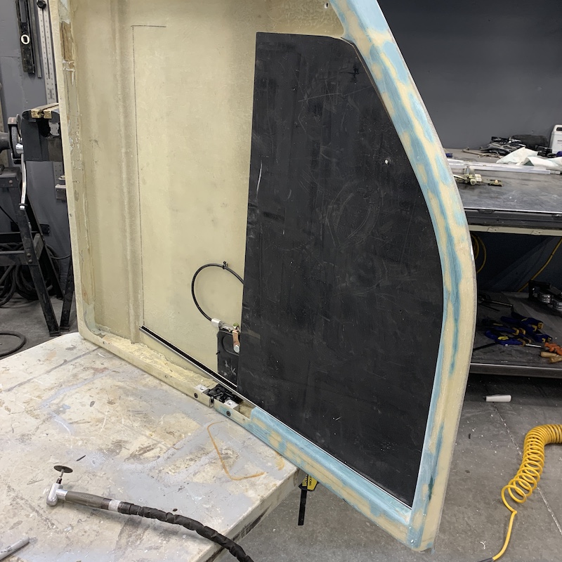
If you're going to have air conditioning, you must have power windows.
Temporary slot for the window - it uses a flat pane and I'm waiting on the channel so I can get things fully dialed in.
Overall quite pleased with the way they work - and they weren't too terribly expensive off of Fleabay. Street Rod Flat Glass Power Windows
I also have my condenser for the air conditioning system on order - another Fleabay item that goes right along with the Jeep radiator I got off of Fleabay. I gotta stay off the internet...
Look what came home! WOO HOO!!!!
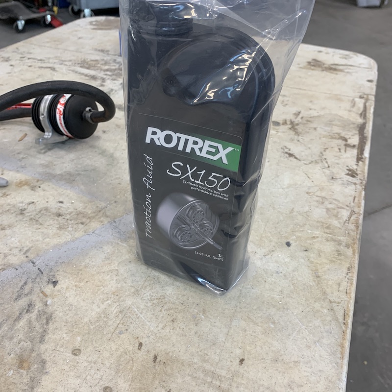
They forgot to send a bottle of oil. The stuff must be magic too - $107.74 for a liter (litre) - it's on the way. Rotrex is VERY specific about using it too.
Jun 6, 2020
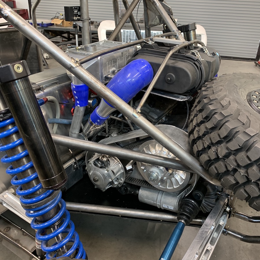
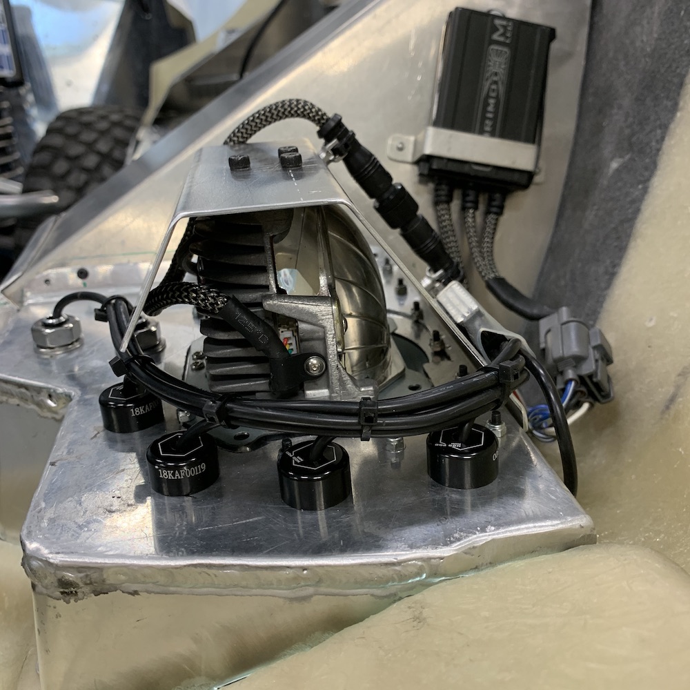
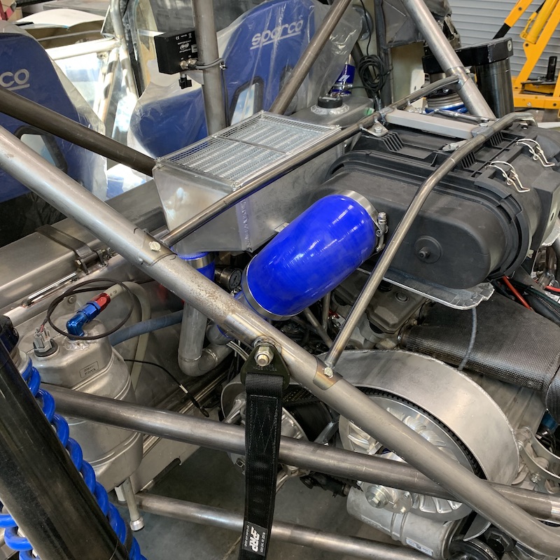
Supercharger in place. YAY!!!
Pretty blue toooobing connecting all the components.
But...
So as I'm reading Rotrex's installation instructions online (I've never had any sorts of instructions with MPI kit) they have little pictures of setups and they say, right there, "Do not mount the reservoir, filter or cooler above the supercharger. This can cause leaks."
Okay, hold on. This sealed unit can leak if stuff is above it?
uh... My res is above it and the radiator is half way above it.
Uhhhh....
Now I'm informed that my setup may have been the culprit behind the leak and not a bad seal and I waited 5 months? Uhhh....
Shit, shit, shit, shit, shit.
Shit.
Shit....
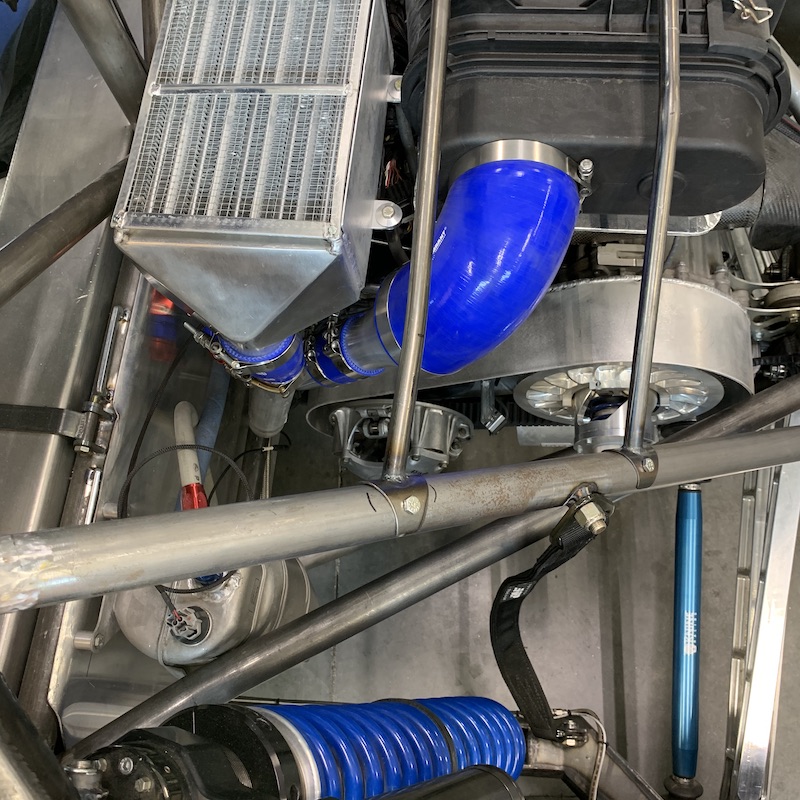
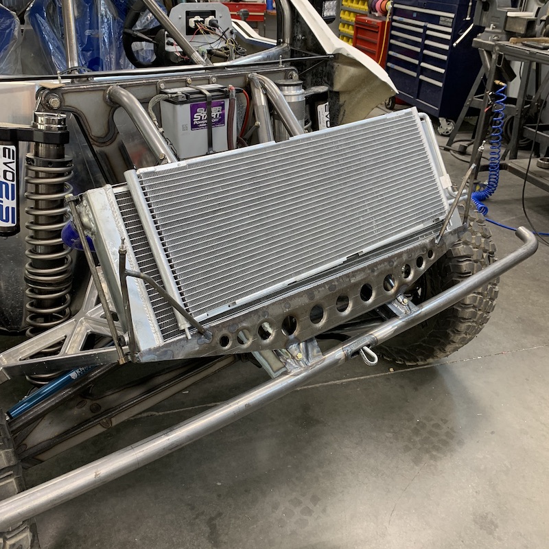
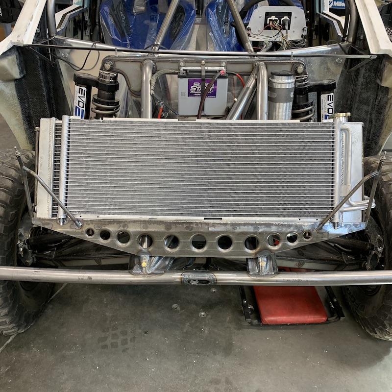
So now I'm in process of moving everything down. And of course, guess what... There's absolutely NO place for the present radiator - where I had it was pretty much the only place it fit w/o getting in a fight with the shock or the back tire and the stuff that'll be coming off of it.
Lots of sitting, staring, holding, moving, staring, swearing, later I decided to search out similar sized radiators and see if I could find something that fits in a spot that's good. Yup. Summit Racing had one, now I have one. Cardboard template made off of specs found at Summit showed me the light. New fan shroud and mounting shall happen.
Right now my build A.D.D. has kicked in and I'm back on window patrol.
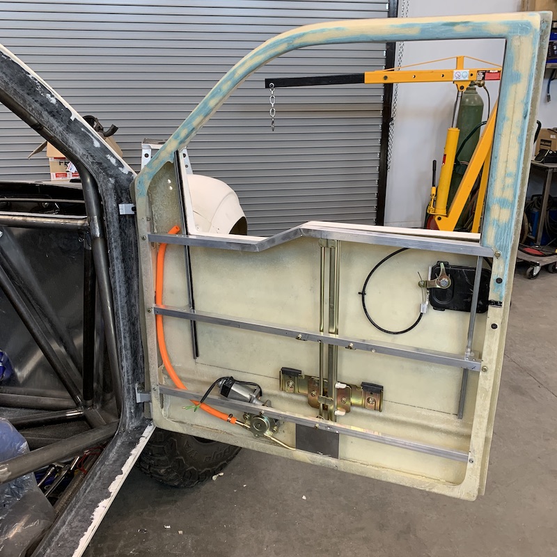
The first round of install works - there are some issues. I'd already planned on getting deeper into it once I got the window tracks in hand.
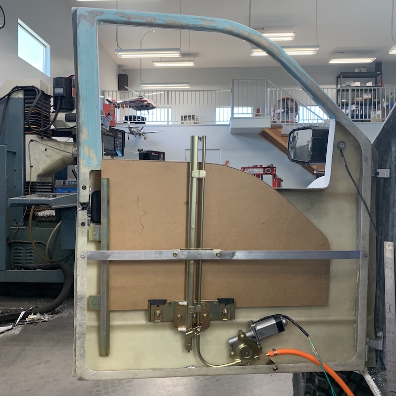
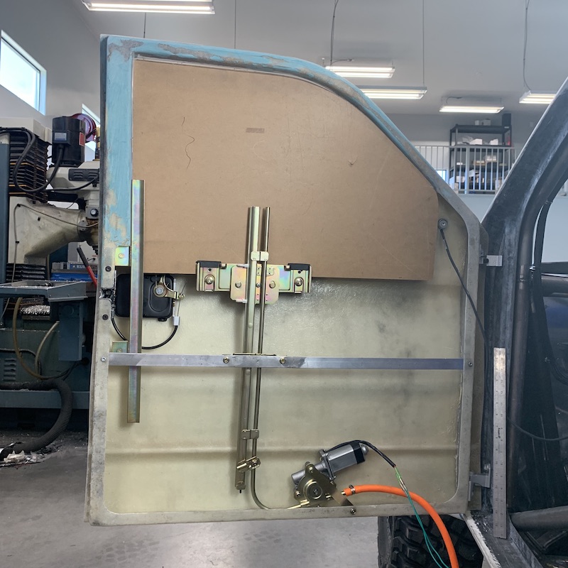
Stiff track in place in the back of the door - everything has to work off of this. Not gonna be easy...
Since the cardboard stuff is kinda flimsy I've stiffened it up a tad - mimic glass/Lexan better.
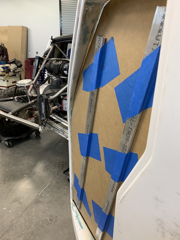
Replaced the .0625" thick angle cross braces with .125" for stiffness. It also gave me a better place to mount the actuation motor assembly.
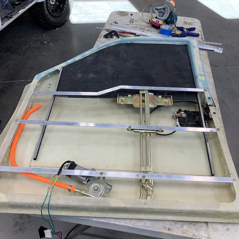
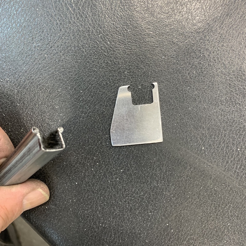
Made little stand offs that hold the track (really well - actually impressed with how well. patting myself on the back for these little gems)
Door installed again with the newer, better setup.

Still not sure what I'm doing for glass. Have a lead on someone that may actually be able to manipulate safety glass - heat to flex point, make it fit, retemper. Supposedly pretty easy and not wallet hateful. I'll find out more this coming week.
I'm presently working on the driver's door. Impressive how much more quickly the job goes the second time when you don't have to dream up crap to make it work - you just copy the dreamed up crap and mirror it.
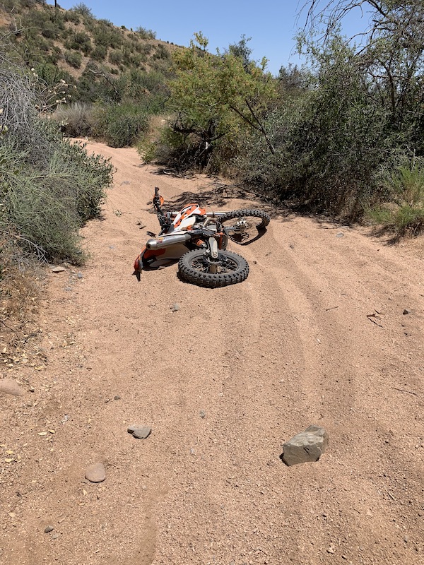
Weather broke this morning (we've been 108-112 this past week, 10 above normal) and it was a nice mid 80's so I had to go get a ride in.
Damn sneaky rock.
Turned left off of single track hard pack into the wash and the bastard grabbed me front wheel and said "DOWN WITH YOU!" - I obliged. Stepped off over the bars, had a nice sit down. No harm, no foul other than having to pick it up.
Love the deep rut left as the front end tucked and then started washing out.
Jun 12, 2020
Got my new cooler and knocked out a shroud (or three). First one (seen in the top of the pic) was a complete moron mess up on my part - forgot the tabs to fold down the ends. Duh. Fit nicely but there was room for improvement. (as always)
Second one was good - right up to the milling machine grabbing it and throwing it whilst I was doing some fine trim work. Thin stuff can be really touchy about being held in a vice and, well, it wasn't happy being milled so it jumped and ran and got tossed in the can.
Shit.
Third one - yeah buddy! Perfect fit.
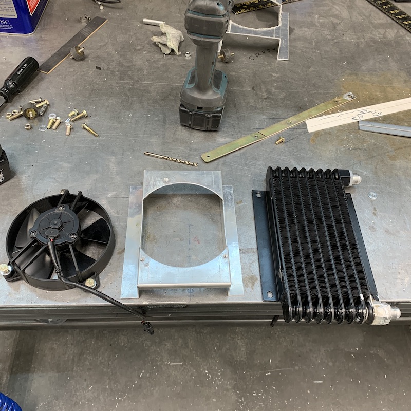
Notice the nicely machined 1/2NPT to -8AN fitting on the right side? Pretty, isn't it. It came out perfectly. Fits like a glove.
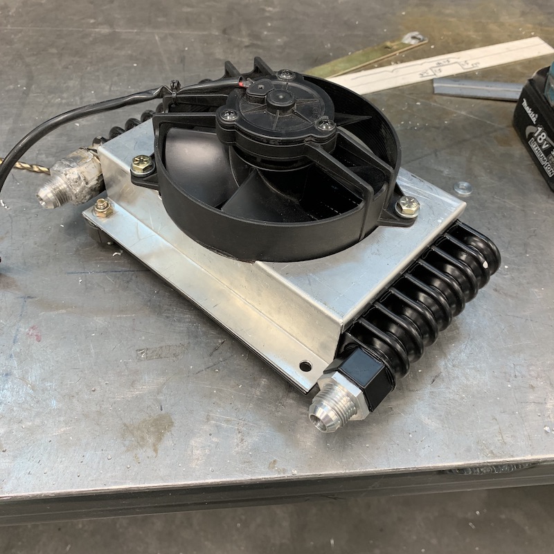
See this one? It came out what looked to be just like it's friend in the other port. But no, it was hiding a secret - it had a burr that I didn't see. I hand tightened it to check fit and as soon as I put it in reverse that little bastard burr stuck his head out and grabbed hold. No removing the adapter. I got even with Mr. Burr - I just welded his ass in - and got it fully sealed on my first run. Getting better at this aluminum stuff.
Much discussion and research and it has been deemed that 1/2" of clearance is all that this little guy needs for cooling ability. It's mounted on four little rubber isolators that are, you guessed it, 1/2" tall. The radiator, with shroud, is really well protected from crap off the wheel by the shock and the air coming to it should be pretty fresh - I may put a small deflector under it to pull fresh air from under the car up to it. We'll see. Regardless it's not going to be seeing recycled air.
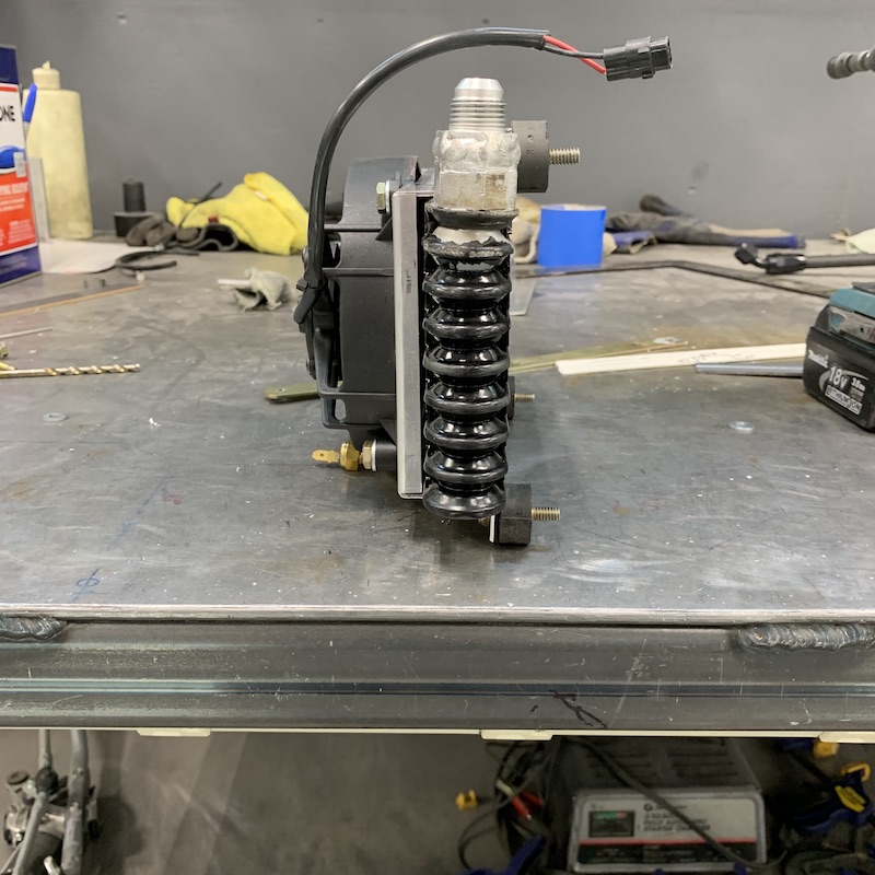
So to make sure nothing attacked it (sway bar arm) I had to fully droop the chassis:
And there's just enough room there at full droop yet keeping the top of the cooler lower than the centerline of the supercharger - Rotrex was VERY specific about this.
Check/test/is it gonna fit:
Yes! YES! It does fit!
For the record, this is fully dropped and bound suspension. It actually stops on the shocks about an inch less - so there's more room. This is worst case scenario. I'm paranoid about things hitting things so I've tried to keep things apart as much as I can in what little room I have. I think I'm up to 17 lbs of shit in a 10 lbs bag now.
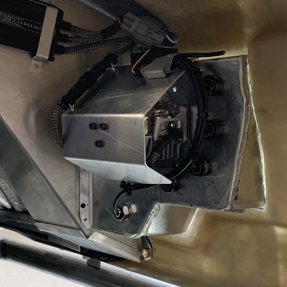
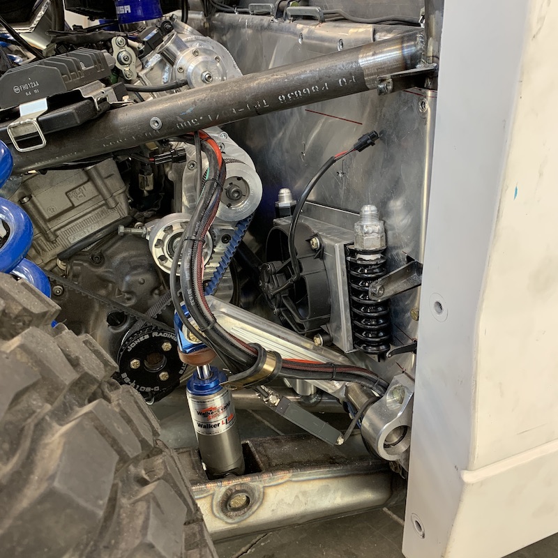
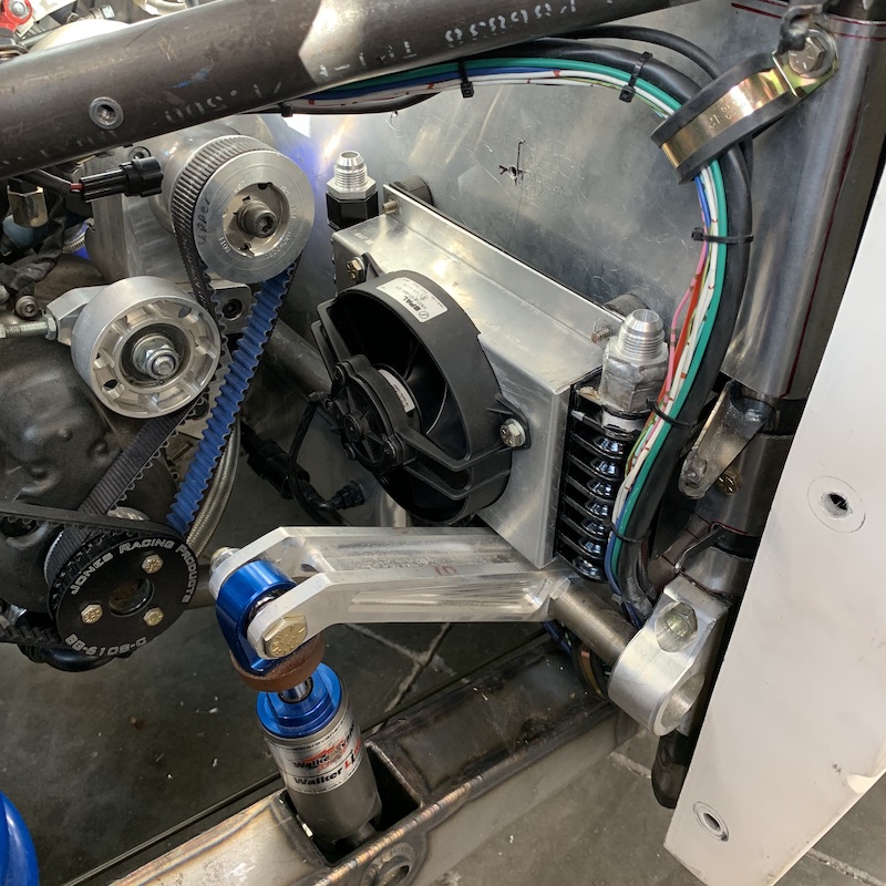
Next the reservoir and filter had to find homes - once again, below the supercharger's centerline. Used one of the old original cooler mounts, made two billet clamp/rings and threw in a second mount down low (fortunately there was the perfect spot where another mount sits).
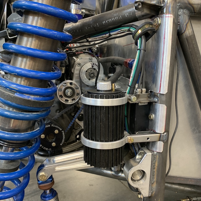
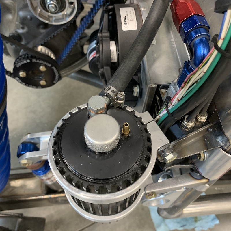
So now I have the correct setup and a bottle of magic supercharger juice and it's all installed, the supercharger is (allegedly) primed (I don't trust it - will be checking this again) and all systems are go.
Magic Supercharger Juice - $107.14 for a liter! And it must stay below 176F (80C). All this cooler crap BETTER WORK!
I still have to program in the AiM temp sensor that's in the bottom of the reservoir but that should be pretty quick and easy.
It lives and BREATHS!
And makes cool whine noises when you touch the fun pedal. I've not let it rev above about 3K RPM yet as per Rotrex's instructions. I want to make sure everything is correct - fluid levels, temps, all that stuff. Once everything says "I'm good”, I'll see what happens - expect video.
Have to pull out the instructions on the Dyno-Jet Auto Tune and programmer. Time to put it to work. (and put me brain to work - new stuff to me, learning curve is hopefully fairly flat).
I'm scared... I'm afraid I'll be making whining noises if something goes poof-ka-boom. All this time, work, waiting... It's finally "done" - at least far enough to go start testing and I'm feeling excited and anxious at the same time.
Need to go get the license plate and title work done so I can go off roading with it too.
Jun 13, 2020
The first supercharged run.
Jun 14, 2020
bdkw1
So did you get the data logging working?
Me
Not looked yet. Was a bit excited and didn't pay any attention to anything other than trying to get it to cool down. Had to get back to the house, too - dinner was on the table.
Cooling system is "correctly" warm - all tubing is hot to the touch but not burning - need to do an IR check of one of the aluminum tubes. Still getting a very high reading at the outlet from the head that fluctuates. Will suddenly spike 300 (!!!) and then drop to 180. No signs of overheating, though - no hissing, no bubbling, nothing smells hot (except my c/f covers for the exhaust - prolly not gonna work even with the insulation backing. Gonna ceramic the exhaust and probably wrap it too - if nothing else to help quiet).
The heat thing has me baffled.
Gonna try that vacuum technique you shared and see if there's a bubble somewhere. Cracking the sensor loose immediately leads to leaking fluid instead of any sort of air sounds so...????
Actually been trying to figure out how to pick it up by the front end high enough to get all the air up into the radiator. Was trying to figure out where to tie the winch hook on the side of the shop - just pull it up the wall. Don't have any trees big enough either. I wonder if a Saguaro can hold an extra 2000 lbs?
RPM and boost pressure are not reporting. RPM - I have to go back and see where the pickup is - I may not have gotten it plugged back in when I was tying down the loom. Not sure what's up with the boost pressure sensor yet.
Still have to rewire it so the two supercharger related fans (sc cooler & intercooler) turn on at 1 psi of boost and let the Yamaha ECU control the cooling fans.
I MUST get a spark arrestor setup on it. Sleds don't have arrestors because they are used in the snow - it doesn't burn. I'm watching a fire in the distance right now as I type - look at the grass funny out here right now and it just goes poof. I will NOT be responsible for a fire.
The list of stuff grows shorter!
---- initial thoughts ----
It's really linear. I kept expecting the turbo hit like my brother's Canned Ham and it's not there. It just pulls. Notice how easily it lifts the front end with the fun in the video. - there's no damping in the shocks, so it's really sloppy loose but still, it sure is easy to make the chassis weight move with the pedals.
The tuning is whacked - have a DynoJet auto tune that I need to learn along with power commander that it talks to. Been following a thread on the Yamaha sled sight about tuning boosted engines with the equipment I have for a couple years now.
Clutching is off too but I'm tickled with it already. I'd like it to grab a tad earlier and not quite as abruptly. May be a belt length thing - can close the secondary a tad more. Once I get the gauge reading RPM again I'll be able to go mark off a section down the street and do runs.
It has a lot of potential to be pulled out.
Suspension - totally open on all bypass circuits (not even sure the shocks are charged) and so couch like! Springs feel good over the little rises and it tosses and slides with both brake and throttle really nicely.
Will be easy to dial in.
HA!!! Watch the G meter. There's a slight delay in it and noticed this same issue with another vehicle.
I need to figure out how to measure vertical G loading.
Have pressure sensor for brake system - need to install it and now I think I want to do throttle monitoring too. Have just enough ports left.
Jun 15, 2020
bdkw1
So the temp gauge is on the outlet side? That is going to jump all around.
Me
Arrrrggghhhh! No, I think it's on the inlet side - but it's after/before/somewhere in that coolant recirculation loop. I'll be looking over the service manual in a bit and seeing what the f is going on.
It acts like the thermostat is cycling and the whole system hasn't bumped up to temp. Gets the engine bypass hot, dumps, gets cold water, closes, repeats. Should eventually get everything warm, shouldn't it???
bdkw1
Sounds like your T-stat is either open or closed. No modulation. Odd.
Do those T-stats have a bleed hole in them?
Me
Yes.
Found stuff...
Shitty day
Big air pocket in the outlet. Fixed it and modified a couple things. Appears I cut the sealing o-ring putting it back in. Last piece out... shit. More later....
Both the mill and lathe controls got zapped by an electrical outage last night.
Not a happy camper.
Jun 18, 2020
TheDoc
I see the G meter is biased to the long haired hippy dude side of the car. hahahahaha
Me
LOL!!! I'll weight balance once it's completely done. - probably need to calibrate the G meter too. Found a page in the AiM software the other day that lets me do that.
TheDoc
Great work man, that will be a hell of a hand full throttle steering through the desert.
Me
Hopefully.
I like steering with my right foot.
I noticed that where I did an on the throttle 180 a couple days ago (not uploaded video yet) that it left a pair of very healthy black marks on the street - and they're a LOT longer than I'd have though. Makes me giggle!
As much as it doesn't have any sort of hit, like a turbo, it doesn't give you a lot of acceleration feeling - just sort of sticks you in the seat and continues to pull.
The closest thing I can think of in the way it just accelerates is like the last generation Ford GT. Got to drive one (and the damned door about knocked me out when I exited - what a stupid design. Can't see worth a shit out of them either) a few years back for 10 minutes or so and straight line acceleration was the most linear, non exciting but exhilarating, pull I've experience. Almost electric in delivery.
Here's a dyno chart (turbo, not SC but output is very similar to the chart that I used to have) of how the Nytro delivers - notice how completely flat the "curve" is? Race Gas at 11 psi is probably the closest to what I'll have once I get everything tuned and running.
[IMG]http://www.fullpowerperformance.com/wp-content/uploads/2014/05/FPP_Nytro_Stage2_Dyno-Results1.jpg">jimmyg
Threw it into a few corners and it played nice. Sat nice and flat. Few finishing touches and a compound supercharged/turbo Hayabusa V8 and your done!
Me
You're the third one to mention how flat it stays. I had to go back and watch the video a couple times and yeah, it is. I guess I got the swaybar fairly close. It was a total guess too. It's .0625 (1.58 mm) walled chromoly (springy). I wanna say it's 1.25" (31.75 mm) diameter - went with larger diam for initial run. Can always turn the pieces the tubing is attached to down to accept 1" (25.4mm) if I need it to be lighter.
There is SO much going on when I've done the two runs that I'm only absorbing about 10%. The heat issue (addressed below) has had my attention more than anything else so my focus has been there.
Good God I can't imagine what a double forced induction V8 Busa would be like! (FUN!!!!) The one in the Radical (first gen, "only" making about 380 hp) was wicked. There's a BIG, BAD Genie living inside and he comes out around 8K.
-----------------
As mentioned above - been a funky assed week. Monday night's power getting knocked out twice started it all.
During my last run I was getting wild temp spikes - over 300. NOT GOOD! WTF?????? Same issue I had on the initial couple of runs. I figured there was an air pocket somewhere in the system and it turns out I was right.
To find it, I had to pull the entire intake system; Intercooler, plumbing, throttle bodies and a bunch of wires attached to all the crap. Fortunately, as much as there is, it all comes out with surprisingly few tools. Screwdriver for hose clamps, 7/16" box end and socket, 1/8" allen key, 10mm socket and pliers. I'll admit that I was a bit intimidated to tear into it all at first (there's 17 lbs of shit stuffed in a 10 lb bag) but as I got going, it looks a lot more complicated than it actually is.
Whew. Good job on who ever engineered it!
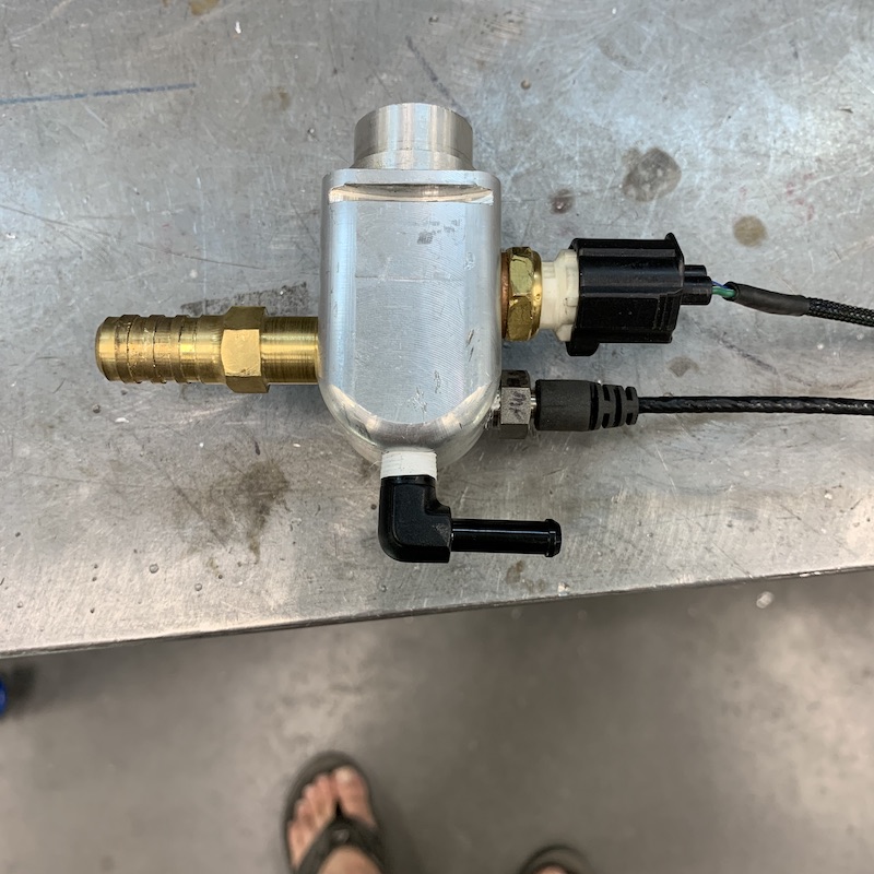
After pulling everything, there it is - the manifold for hot water out.
I decided to see if there was air or coolant in the manifold and to keep from making a big mess (that'll come today) I figured I'd just crack a sensor and see if it leaked. Cracked it loose - nothing. Pulled it out - nothing. Uh Oh!
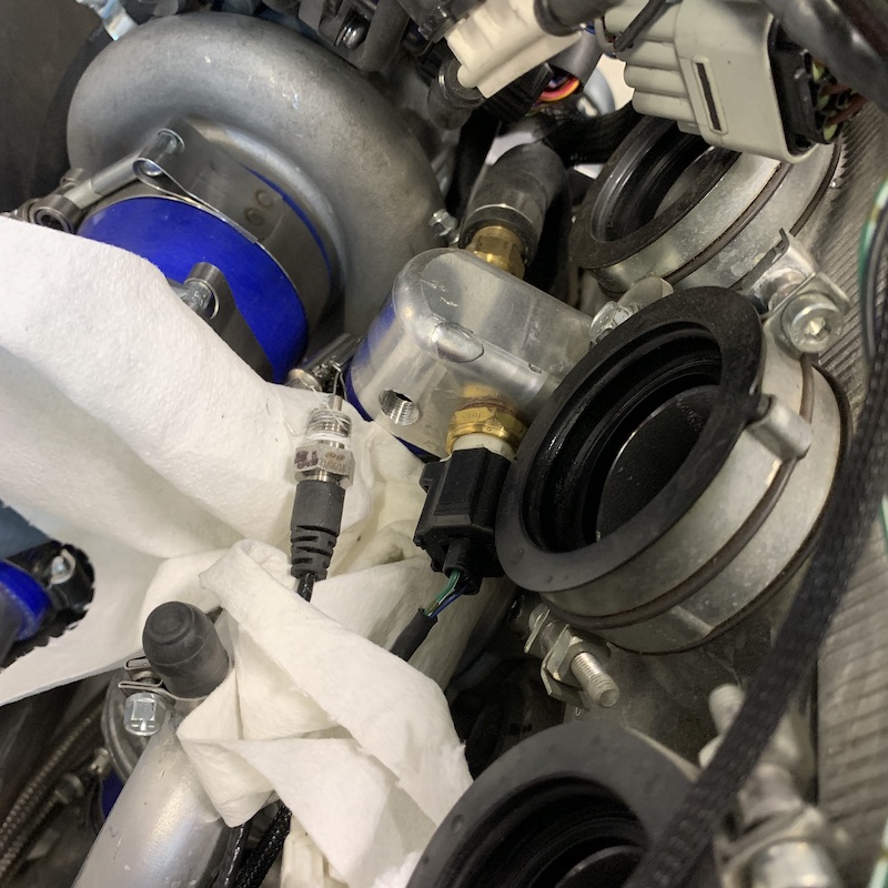
So that leads back to going over the cooling system in the service manual. Unfortunately it's all drawings and they've separated the system over a couple of pages so chasing exactly what line whet where took a bit of page flipping, pointing, grunting and a pen to mark shit.
Hmm... Maybe.... I might be onto something.
The OEM setup has this little double loop circuit on a 6mm I.D. line. One of them comes off of the water pump and goes to the throttle bodies (throttle body heat - snowmobiles need warmth or you get carb icing like an airplane) and then that goes onto a nipple that puts the coolant back into the circuit. That's a definite "NO NEED".
Then there's the other little line on top of the water pump that feeds to the OEM manifold and it's called the "Water Pump Bleed Line" - Hmmm.... does that mean that it's a line designed to get rid of air somehow?
Couple of phone calls were made (The Wizard didn't answer and my buddy Jay, who built the Coyotes, which are Yamaha Powered). Talked to Jay about it and he said "Yamaha doesn't put stuff in that doesn't need to be there." Really good chance there's your issue.
I pulled the manifold off and it was dry as a bone inside. NOT GOOD! The coolant level was about 1-1.5" down into the output line. I've found my issue. A bit of new (actually old, just reinstalled) plumbing was done. Off to the mill with the manifold to punch a 1/8NPT hole into it. This is when I found out the controls on both the mill and lathe had been dorked by the power surges.
Shit.
Put a threaded hole in the manifold and screwed in a fitting. I now have the water pump bleed line back in.
I put the system back together and then worked on getting all the air out. This new nipple is the highest point in the system so it's the perfect spot to put the vacuum on and start drawing coolant in. I used the bleed nipple on the thermostat loop as my filler line, as it's the second highest point (and has always flowed coolant when the cap is pulled - hence the idea that I'd gotten all the air out but alas, it's about 2" lower than the manifold).
As I vacuumed I got air and then I got coolant. The coolant kept having air in it, though. You know when you have a cracked straw and try to drink how it gets little air bubbles in it? Same thing. I was thinking that it was just trapped air working its way up/out. Still kinda strange that it kept drawing air, though. I let it sit for a bit, came back and put a light vac on it and got just coolant - no, a couple bubbles.... hmmm....
RIGHT HERE I SHOULD HAVE STOPPED! It's a closed system. There shouldn't be any air leak. I'm too stupid to take that into account (yet), though. My gut told me that the constant little stream of air that I was getting wasn't right but did I listen to my gut and try to figure it out? Of course not! Why would I be smart and chase some (other) ghost in the system when I'm thinking I've just eliminated the current specter?
I put it all back together (surprisingly quickly) and started it up.
Temps start coming up nicely - much less erratically than they had been. Okay, cool. Shit's good. Let's go for a test run.
As I back out I see a nice little puddle of coolant underneath where the Mini-Raptor was parked with a trail of drips on the floor leading to where I'm now sitting outside.
Okay WTF?
Out comes the creeper, under the Mini-Raptor I creep and look up and there's a nice little stream of coolant coming out from the area where the manifold plugs into the head.
Well shit. I've either cut the o-ring or possibly folded it when I put the manifold back in.
Pull a vacuum to get the air out and guess what? If you have a compromised o-ring, it's gonna let air in the system. You know, like a straw with a crack. - I'd seen the issue, just didn't recognize it. It told me all about the leak but I was too dense to put the two together.
I had to walk away for a bit. Frustration level with the leak and the zapped machine controls was at that point where you just have to put stuff down and walk away. Stayed out of the shop yesterday with the exception of about 20 minutes of getting the machine controls taken care of - have a pair on the way.
Jun 19, 2020
I think I got the cooling system fixed.
The o-ring in the water manifold was compromised. New o-ring, no bubbles, air all removed.
Took just over an hour to fix it.
Started it up and let it run until I had a steady 180F. It would cycle up to 190ish then drop back to below 180. Finally settled in at 180.
When on the throttle it gets up to 225-230 but goes cool as soon as I'm off throttle. Since the OEM system takes the temp right at the output I followed suit. I need to take it at the water pump inlet instead. It's surprising how much the temp coming out fluctuates (was told it will).
While it was sitting and idling I screwed around with the Power Commander. I have absolutely no clue what I'm doing so far!
I need to get the auto tuner up and running so I can develop a map.
Top end is probably going to be around 90 mph (145 kph).
Still not sure why I'm not getting a tach.
Throttle position is working on the display. Waiting on a cable to get brake pressure reading.
@1:52 - full front end air and full bottom (shocks are still fully open on all settings). You can hear the left front tire scrub a small, removable rib in the bodywork. Clearance needed. First of many, I'm sure.
bdkw1
Nice!
Yeah, the output side of anything will just scare you. You should see the oil temps coming out of a T400, it's enough to make you put tape over it and ignore it.
Me
Once it settled in and cycled around 180 I was pretty relieved. It wasn't doing that with the big air pocket in it.
When I saw 325 on a run I kinda freaked but remembered you saying "output temps will vary with use" - yeah, no shit. Still backed it down and limped back home.
Now it hits 225 on the gas - that's not outrageous compared to the 180ish input.
I'll keep this sensor in place right now - but when I do all the rebuild/reassemble I'll move it down into the line before it hits the pump. There's a little aluminum toooobing jumper that I'll stick a bung onto.
-----------------
Just talked to a buddy that's a killer tuner and has a dyno. He's well versed in Power Commander. Looks like Monday's a teaching day.
Still chasing the RPM issue; been given a few ideas on trouble shooting.
Gonna upload a basic dash that only has the tach to see if it's my programming (because it was working). Simple, quick.
If that doesn't work, I'll throw a loose wire between the dash and the coil pack input to see if it's a shielding issue because I have all the wires zip tied together.
If that solves it, I'll have to pull the present signal line out of the harness and either use a shielded line or maybe just let it hang around with its friends but not be looped in with them. We'll see.
jimmyg
Far the @@@@ out! Your gone and built your self an animal! 77mph in the blink of an eye. I truly don't think you need anymore power. That yellow dog on your back must be proud as hell because that thing is epic! Just epic. Power steering was mint. It was so stable for something with so much suspension travel. I'm out of words. Wow.
Jun 20, 2020
Me
Thanks Jimmy! Much appreciate the compliments.
Looks like all that design work that flyerrider, JD66 and I put into the front end design and then (cheating) copying the X3 rear end is going to be a quality combo.
Power - can always use more - Just have to have a well tuned/trained right ankle to use it appropriately. Fortunately I've got a quality amount of time behind high hp stuff and know how to be smoooooooth on the fun pedal (or twist throttle).
Taking it into a shop with a chassis dyno on Monday - buddy of mine, that I met the very first time I came to AZ back in '99, has a shop and is an exceptional tuner. We should be able to get things dialed in and see what sort of hp it's making and putting to the ground.
-----------------
Once tuned, I'm really looking forward to getting out in the desert with it and start playing and shock tuning. BUT before it goes anywhere near the dirt I MUST put a spark arrestor on it. Snowmobiles don't have spark arrestors (hard to catch shit covered in frozen water on fire) so one has to be added. Just look at the grasses here right now funny and they go poof and we're just getting into summer months. I do NOT want to be responsible for causing any charcoal.
A couple of months back I set a very small one laying my KTM over after a high speed run - hot header and dry grass makes one do the MX Boot Stomp. Scared the shit outta me. Smelled something coming from under the bike, quickly flopped it over and then started dancing.
Bad juju!
It's gonna be a bad next three to four months for fires too. The news last night reported that we presently have five (major) fires burning here in AZ.
Out of the 600+ fires last year only 10-15 were natural cause (lightning). The rest were man made; cigarettes (why in the world anyone would throw one out of a vehicle here is beyond me - f'n morons!) and trailer chains dragging are the two main causes. One guy set 26 little fires along one of the more traveled state routes up north last year with dangling/sparking chains. He made the news...
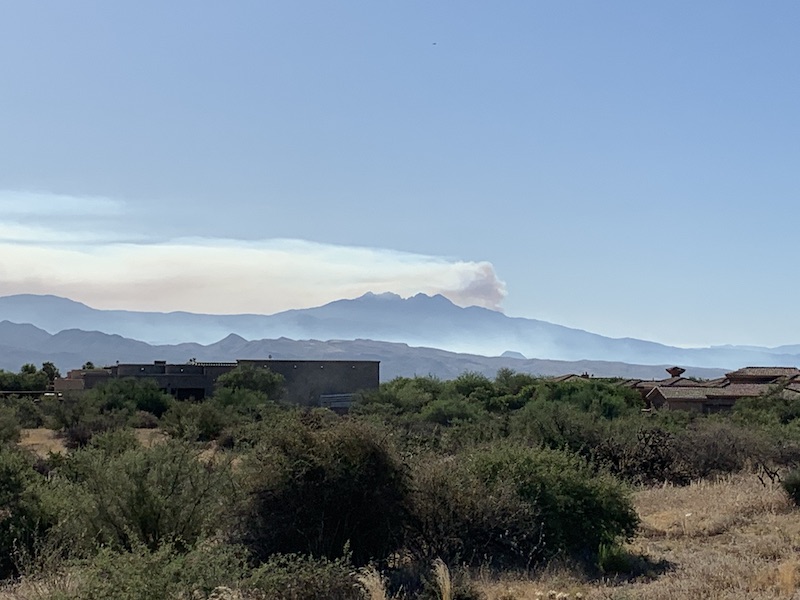
We presently have the fifth largest fire (and well on it's way to the #4 spot) in Arizona's history blazing about 40 miles (64km) from me as the (non-drunken) crow flies. Local news shows 175K acres, 7% contained this morning. We live about 10km south of the F in Carefree on the map, just to the right of the white line heading into it.
Been watching the smoke rise off of it from our back yard for the past week. It was started by a troubled car pulling off the road (catalytic converter probably ignited it) last Monday.
Here's a shot from down the road (where I go into the Tonto National Forest to ride) yesterday around 8:00 a.m. The fire's climbing up the back side of Four Peaks.
Jun 28, 2020
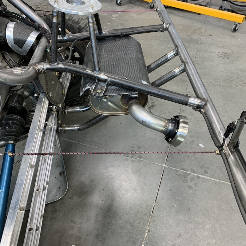
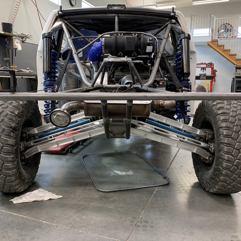
Spark Arrestor in hand and then installed.
Wanted to use a screen type but trying to find one that fits a 2" (50mm) tube didn't happen so I ended up going with SuperTrapp. They've been around a long time, work, and have proven to be a pain in the ass for me. Stupid stover nuts on stainless fasteners always gall up even with the thread stuff they supply. Got five out of six installed and removed the allen head cap part of one.
Now that I won't cause any fires, it'll be time to go test and tune. Still worried about the temp spikes I'm seeing on the output side of the engine, right off of the head. I have to relocate my water temp pickup to the intake of the water pump so I know what temps are happening on the input side of things.
Anyhow, here's the muffler/spark arrestor work:
Supertrapp 2" sparky:
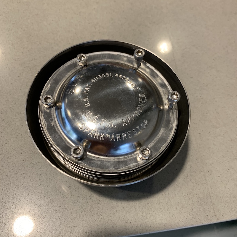
SuperTrapp body welded in place:
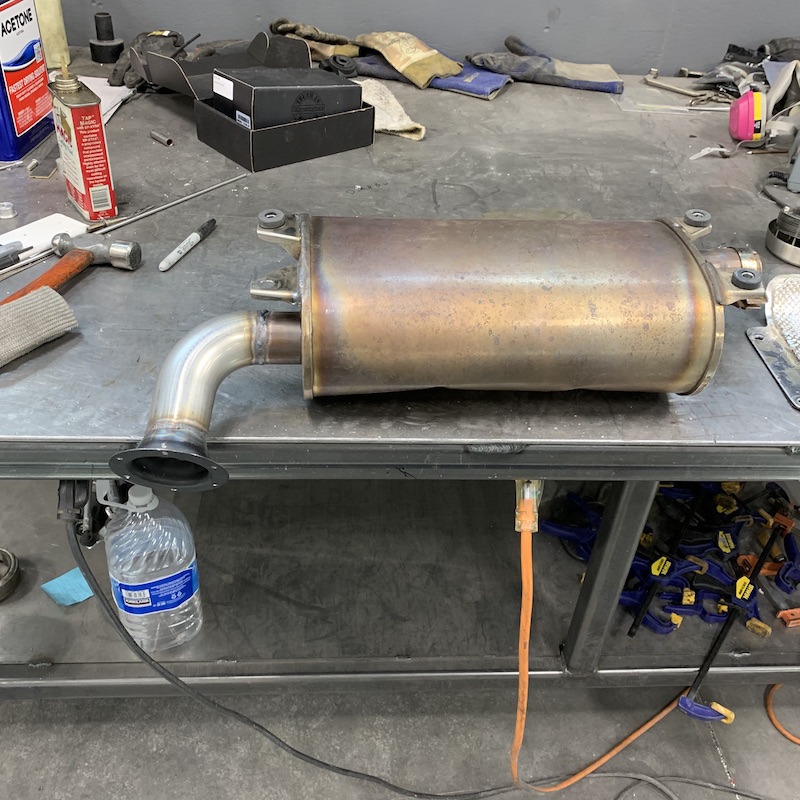
Installed:
It's been HOT here - hovering in the 110F (43C) range. Too hot to load up and head to the desert presently.
Gonna mess with the cooling system some more and see what I can do about the high exiting temps (maybe nothing? - research needs to be done).
SOOOooooo close to getting to go out and play with it!
Jun 30, 2020
darwinpayne2000
A SuperTrapp spark arrester.
One more thing that I need to buy for my buggy. Thanks K-Fab. I think.
Me
If you have a muffler that has packing (Magna-Flow) be wary of the SuperTrapp.
Trapp is correct as to what it does to the packing and it makes your engine go sputter, putter, put, put, cough, die.
This is what came out of the Magna-Flow on the DezII and plugged the Trapp

Jul 1, 2020
Three rounds of quality work was had yesterday along with one little "I guess I should have gotten stitches" moment...
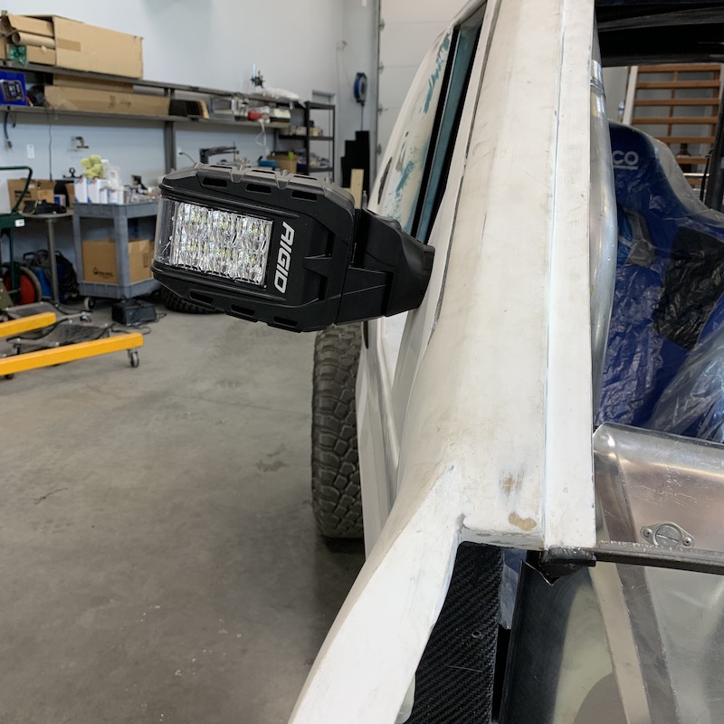
First - Mirrors
Rigid Reflect mirrors are pretty sweet - have them on our XP41K. Not only do they have turn signals in them but they have flood lighting that spreads out into the peripheral area of vision. They make for a good fill in from about 1:30 and 10:30 back. It's surprising how much more they fill in the big picture at night.
The downside of Rigid is getting parts. I need a second pair of the adjusting wedges. The stockers don't have enough range and my mirrors aren't sitting flat.
Got in touch with Rigid (they're a local company) and the guy I talked to said "We don't sell just the rings but we can put in a warranty claim and get you a pair. I'll send an e-mail."
A couple days later, still no e-mail. Get online, start hunting and pecking on the keyboard and find Rigid Service and send them an e-mail.
Thank you for your email reply.
The item that has broken we do not sell or ship.
But we can service the unit for you.
Please email me back with a few full pictures of your whole reflect light.
So we can email our techs to provide us with a service repair quote for you.
I snapped a couple of pix of the rings and of the tilted mirror for them in response.
Thank you for your request.
The item that has broken in your picture. We unfortunately do not sell or ship for service.
We can service the unit for you, for a service fee.
Please email us back with a few full front pictures of your reflect lights.
Showing the complete situation. So we can email you back with a service repair quote.
To which I reply: It's not that there is anything broken or wrong, I need two more of them for more adjustment range.
It's not a service or such, I just need two more of the rings.
And get the response of (italics) (which I responded to in bold)
Thank you for your reply.
Can you please email me a picture of the rings you are needing?
Here you are, again:
(sent two pix of the adjusting wedges)
So we can see if it is something we can sell to you.
That's the idea - I just need two more; one for each mirror that I have. The single ring (as supplied) does not allow for enough adjustment but I can stack them and get the angle that I need. Simple, easy.
Or if it is something that will need to ship in to have serviced. If it is not a piece we sell.
There is NOT a service issue. I pulled the screw out of the back side to mount, the rings are loose. Nothing is broken, there is no service needed. I just need two more of the rings to make things align correctly.
We typically only sell the replacement hardware kits. All other request must be shipped into be service by a Rigid tech.
This part should be available as it's more than likely in the hardware kit.
May I ask why purchasing a pair of rings that are probably worth 5 bucks is so hard?
There's absolutely nothing wrong with what I have. Nothing is broken, nothing is damaged - heck I've not even used the mirrors yet. I just need another pair of adjustment rings. Very simple.
Thank you, have a wonderful day.
Rigid is DETERMINED to get me to send my lights in for warranty work! What in the world? I need parts! Their next response (gee, seems like a previous one - I'm seeing a vicious circle starting to form. Jumping ship)
Thank you for your email reply.
The item that has broken we do not sell or ship.
But we can service the unit for you.
Please email me back with a few full pictures of your whole reflect light.
So we can email our techs to provide us with a service repair quote for you.
I'll not shoot the messenger (would like to strangle instead but it's not her fault, she's reading a script...) but I did send this:
Hi Carrie,
I give up. There is not a broken problem or is there a service problem. I just need a couple of adjusting wedges.
I'm a machinist - I'll make my own.Normally I'd say thanks for the help but I'm just going to wish you a good week instead.
Screw you Rigid! 9 degrees of "I'LL FIX IT MYSELF!"
Which lead to this:


I am pleased.
I also finally found adjusting rings on Rigid's site - 53 bucks!
WTF???
For two little FRP wedges?
Seriously? They cost them maybe 10 cents to make.
I'm glad they pissed me off and I went the route I did.
Got the wires routed properly and connected and all works. Yay!
------------
Part Dos - A/C Condensor Installation
A/C Condenser core in - with remarkably little modification/work. WOOOOOO HOOOOOOO!!!!! I'd ordered the core a few weeks back. Found one that fits the Jeep radiator I'm using (because it should fit - or at least that would make sense but one never knows using Fleabay).
Pulled it outta da boxen it came in, walked over to the front of the Mini-Raptor and dropped it in place.
What's this? It actually looks like it's gonna fit! It's a tad tight at the hood supports and the tubes that lead back to the compressor are interfering with the output line of the radiator.
Hold on, got this... grunt, twist, yank...
Cool, no output clearance issues now.
There was a little grinding and the removal of two pieces of the lower frame edges. I just went after it with a carbide grinder. It dropped right into place.
Really? You're not gonna fight with me?
Thank you, thank you, thank you!!!
Knocked out a couple upper mounts that attach it to the studs I'm using to hold the rad in place and a couple little collets to drop the bottom mounting pins into:
Yeah, this makes me smile even more! Two things checked off the list.
-----------
Part III - Coolant Specter Exorcism
I've put bleed lines in the top of the manifold outta the head.
I've rerouted lines and copied what Yamaha has done (minus throttle body heat line)
I've bled the system, vacuumed the system, sworn at the system and I was still getting really weird temp readings. I knew there was an Air Specter hiding in the system and I had to rid the demon!
Begone you hot air bastard!
Started on the engine end - checked for air in all the high spots, nope, getting coolant. If I'd squeeze any of the silicone lines I could hear burbling. Fine, I'll pull lines up front and start working there.
Pulled the upper line and there's coolant in the tube but none comes out of the rad. Kinda expected this but not to the extent it was(n't).
Pulled the lower return line. Nothing. WTF??? There's a little drip but not much in the rad. Think I may have found my air pocket.
So it was a little more lathe time spent, a 1/8NPT adapter was made and some actually decent aluminum TIG welding was done. I have a bleeder on the highest point of the system now.

Started pouring in coolant until it ran out of the lower return line. Put the line on, kept filling. Half a gallon(!) later coolant starts dribbling out of the rad in line. Attach line, keep filling. The little purge valve was doing a great job.
Because the rad sits at an angle my filler neck is off and it leaves air in the system - and I wasn't smart enough to set it correctly when I put it on. It put me down and totally kicked my ass when I put it on (correctly sealed) the third time.
So I'm sure I have most of the air out now. Squeeze the tube and get sloshing, not gurgles. Good.
Took a brake bleeder system's catch cup and filled it with water. Put a vacuum on the cup and out come de bubbles. Release vacuum and in goes coolant. YES!!! Spent 10 minutes or so pulling air, sucking coolant back in. I'd let it sit a moment and would get more air/water displacement instead of trying to rush it. It finally quit bubbling, got harder to put a vacuum on and didn't draw any water back in. I think I've got it!
Moment of truth - time to start it up and watch the gauges.
It started, then started running really rough - almost like it'd lost a cylinder. Uhhh???? NOW WHAT??? Quick look at the gauges and oh, look at the fuel pressure. It was way low. I'm outta fuel. Dumped a gallon in and she started right up and sat there and purred at me. Good Mini-Raptor! GOOD!!!!
Let the temps come up to about 140F or so and then decided it was time for a little easy "let's see what's happening" run.
I drove around the neighborhood for about 10 minutes at nice slow, easy speeds. The temp came up to 190 and then pretty much leveled off. If I'd get on the throttle much, it would rise above 210 momentarily (temp is taken right at engine outlet so I'm reading hot temps, not return cooled temps). The oil temp and water temp were sitting right where they're supposed to be and following each other appropriately (the Nytro has a water/oil heat exchanger in it).
The Coolant Specter has left the building!
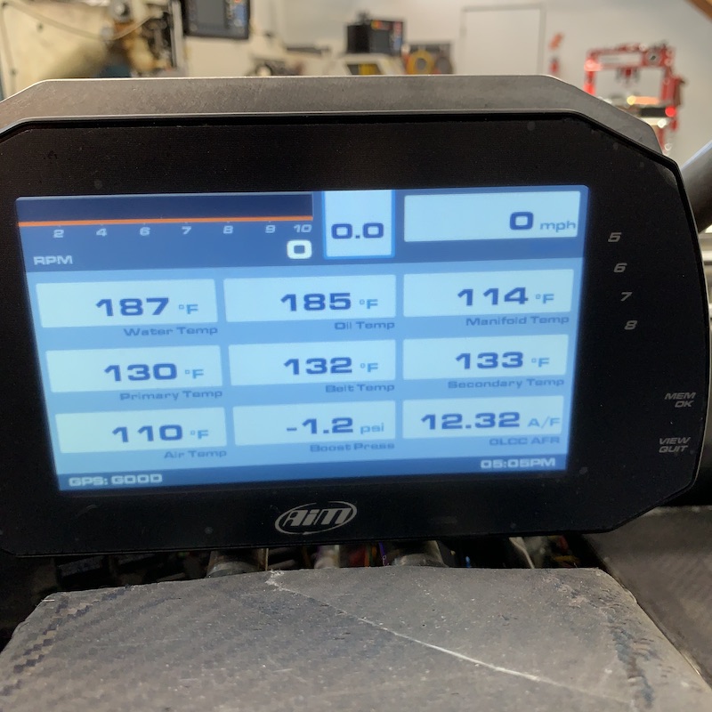
Belt temp setup works flawlessly. The belt and primary clutch stayed within a degree or so of each other. The secondary clutch was reading right at 10F higher when I was running. Will be interesting to see what's up with that and what sort of readings I get as more time is put on the system.
Only getting a max of 3.4 PSI of boost - should be getting 8. Something I have to look into. I'll pull one of the pieces of the filter system just to see if that makes a difference. I should have more than enough air flow available with the setup I have. I did the research, dammit!
Still waiting on a response on my RPM pickup - not sure what's up there...
Stuff never goes this easily. Maybe the Mini-Raptor God is starting to look down and smile at me.
The one down side to yesterday (as mentioned at the start of this long windy) was a possible need for stitches.
Whilst cutting the tabs for the condenser core mounts I was attacked by my big sheet of aluminum that had fallen away from the wall and against my build table. There's a nice square corner about a foot off the ground and I found it as I stepped off off the pedal.
Ouch. Probably needs stitches but I was working so I just went the paper towel to bandage route, holding it shut. Didn't bleed or hurt much surprisingly. I'm keeping an eye on it - don't want infection. If it looks good in a couple of days I'll superglue the edges shut and be done.
Chicks dig scars - I should be a magnet.

I have found one issue - there's a tad bit of rubbing of the front tires against the back of the head light shields. Gonna have to make some clearance. Just one of many little picky things I'm sure will show up as this moves along.
Bad thing now is that I'm down and out when it comes to test time.
We've been under and Extreme Fire Watch for the past month, have had numerous forest fires (including the 5th largest in AZ's history) and the U.S. Forestry has decided to shut down the Tonto (my back yard) and Coconino National Forests. No off roading until we get our first monsoon and the desert gets a drink of water.
Guess this forces me to work on finishing things up. It's hot too (supposed to be 112F (44.5C) this weekend) so until I get the cab sealed and the A/C running I won't complain too terribly much about not being able to go out.
Jul 5, 2020
Looks as if I've gotten all my cooling issues and such figured out.
There will be a lot of tuning and there's gonna be some physical mods for some clearance. The front wheels attacked both headlights in a fight for space on full compression so that's gonna have to be addressed.
Since I'm getting into composite work, I'm thinking I'll be redoing the lights with a composite piece instead of the present aluminum bodies. I'm not really that happy with the headlights anyhow - they've been a bit of a thorn in my side from the start so I'll just go about it in a completely different manner. I know all the wrong things to not do now.
The weather here is definitely a no-go outside during the day now. Summer can be a bit brutal here in the desert. Throw in the fire dangers that we've been surrounded by (our local forest has been closed due to fire danger) and, well, the Mini-Raptor's been banned to the shop for a time.
That forces me to head down another path of this build: The Dash.
Don't know if anyone's familiar with how the Mini-Raptor bodies came into existence but here's a little history on that:
Right at seven years ago this past April I'd finished a carbon fiber dash for the XP900 that I owned at the time.
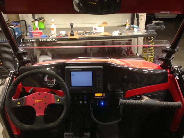
It was the first time I'd done any sort of molding, worked with foam, worked with a wire cutter, etc. to produce a composite part. Here - the whole XP900 mod/life can be found here on Yellow Dog Racing. Definitely look over the shock section.
Anyhow not long after I'd finished the dash I get contacted by benihana from Knine Racing here on Minibuggy about the dash. Seems that me making that dash inspired Ben to produce the Mini-Raptor bodies. Who would have thought that Ben would end up making these amazing bodies because I made a dash? Makes me stand up straight, head high, wearing a grin. Much appreciated Ben! My dash causing his Mini-Raptor business was what ended up putting the Mini-Raptor body I have in my garage and taking me down this five+ year path.
So this next aspect of the Mini-Raptor is kinda pulling the whole project around full circle as now I'm starting on a dash board for the MR using the same techniques I did on that original dash but with experience and guidance from Ben this time.
First things first - CAD work. Pulled out some Cardboard and had it Aid in the Design of the new dash. I've been contemplating the thing for a long time - have part of my mounting ideas figured out, at least around the AiM dash - it's mount will be a key member of holding the dash in.
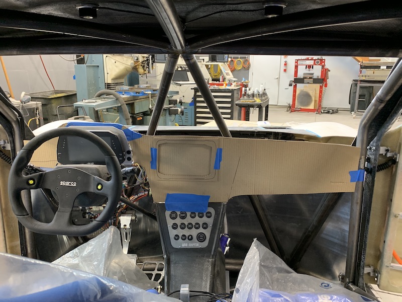
The dash will hold a Lowrance GPS, Icom two way radio and a PCI intercom system (basically the standard stuff I've put in everything) and if there's room a glove box. That will depend on how much of the space behind the thing gets taken up by the HVAC system.
I'd considered running another iPad with LeadNav & onX Hunt like we have in our XP41K but honestly, I'm not that thrilled with the iPad - it glares, you have to download topo/satellite views of where you're going to be and I like the way the good ol' standard of GPS Lowrance units work.
Once I got the CAD piece's basic design figured out it was time to transfer it to good old pink foam insulation sheeting and start forming the dash.

I recessed the area around the AiM dash's aluminum mount so the foam fits nice and tightly and gives me a good base to work from.
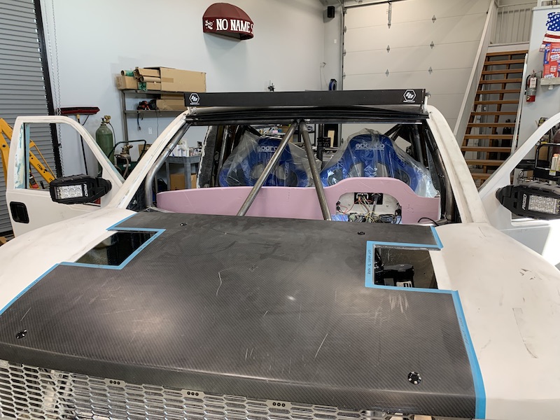
From there it was time to start figuring out the full 3D shape. I started with the dash console. This will all get smoothed out with a hot wire cutter.

The dash will be installed by sliding it forward into the cabin so the first piece with any sort of shape went in, forming the edge of the slot for clearance around the driver's side center down bar. From there I copied (more or less...) the shape of the rise for the AiM dash and started tiering it downward to the lower mounting frame of the windshield.
The whole dash will lay up against the windshield frame and I'll integrate the Samurai! HVAC venting into it also.
Actually, holding the defrosting vents up against the lower windshield frame is what made me realize that the dash had to be the next aspect of this project.
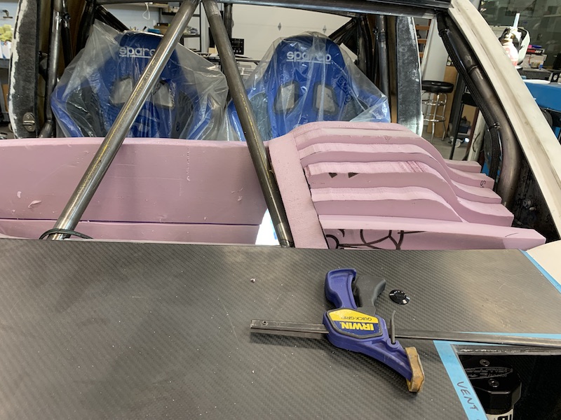
After getting a basic idea of the dash console area I needed to get the other components location figured out. Already knew where the GPS unit was going - cardboard piece shows that.
I also cut a hot wire template for the area around the AiM dash. I'll use this and the lower windshield frame as my guides to form the dash.

Another shot of the dash and it's layout. Had to split the lower part and angle it back so the dash will meet the top of the center console.
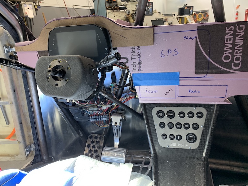
Here's the GPS unit that will get installed. Five years ago, when I picked it up from PCI Race Radio, it was state of the art with new touch screen technology. It'll be interesting to see how archaic it is now compared to the stuff out there. Looking around on PCI's web page I see it's still sold (albeit quite a bit more expensive) so maybe it's still "modern". I don't care that much about having the latest and greatest - this piece should be a solid performer and I'm familiar with Lowrance's stuff so it should suffice just fine. I may be able to flash the firmware with a more up to date operating system if need be. Dunno - speculation. I've not even put power to the unit and have only recently pulled it outta da boxen to see what I have.
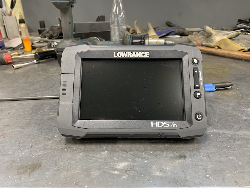
Over the next couple of days I'll get the raw shape pieces in place between the windshield down bars and also over in front of the co-driver's area. Once those pieces are in, I'll start on the hot wire cutting and get a smooth, useable surface and then it's Bondo and sanding time.
Not sure if I'm going to make a plug, then mold off of that and attempt the resin infusion again or if I'll take the same path I did with the XP900's dash and use the plug as the final product and just cover it with composites - should still be able to vacuum infuse the piece.
We shall see!
Jul 8, 2020
Long windy one here. Had half of it written up yesterday and I guess instead of hitting post I hit something else? What ever, it's gone so I'm writing again.
Dug around and found my hot wire bow. Ran a couple of test runs, trying to get the power supply's voltage and amperage dialed in. Just a little extra twist of either dial makes the wire glow nicely and smoke the ends of the bow. That leads to the wire drooping and bad cuts and sometimes wire failure. Made a couple of little aluminum feet to keep the wire from igniting the bow (for the fourth time).
Also, new favorite tool - the electric carving knife. I had no clue it went through pink foam so well. Makes a mess, though.
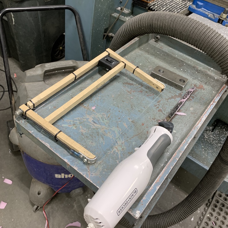
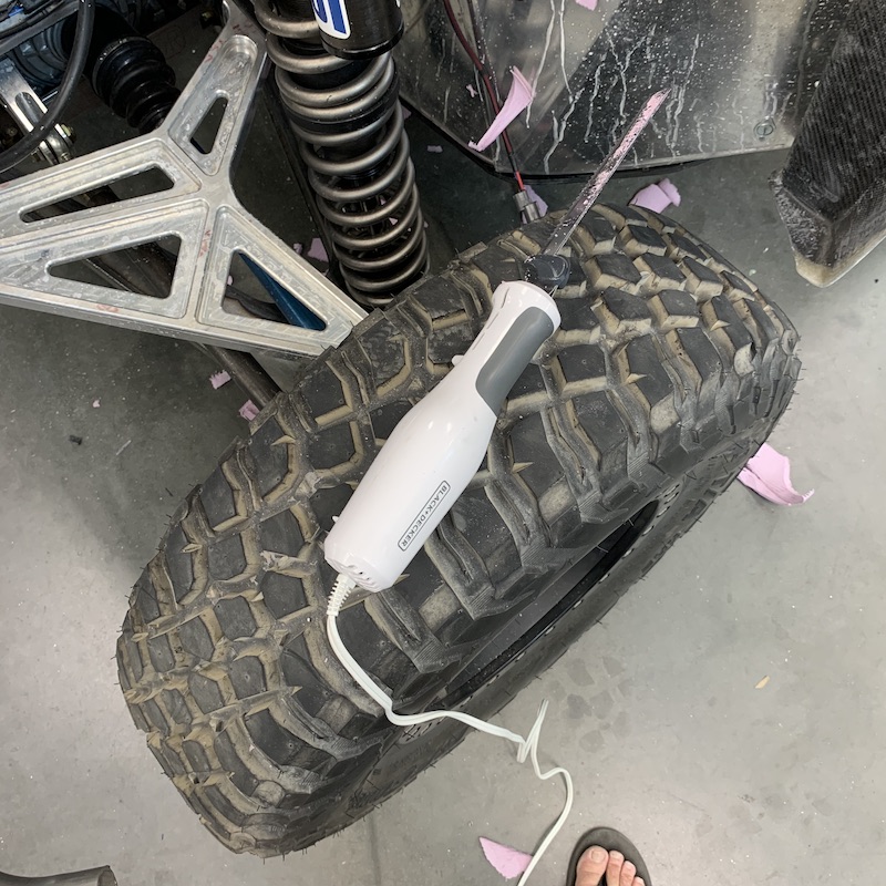
My big coping sander is also really nice to use to make mating surfaces nice and flat. Pink dust is starting to creep onto everything in the shop...
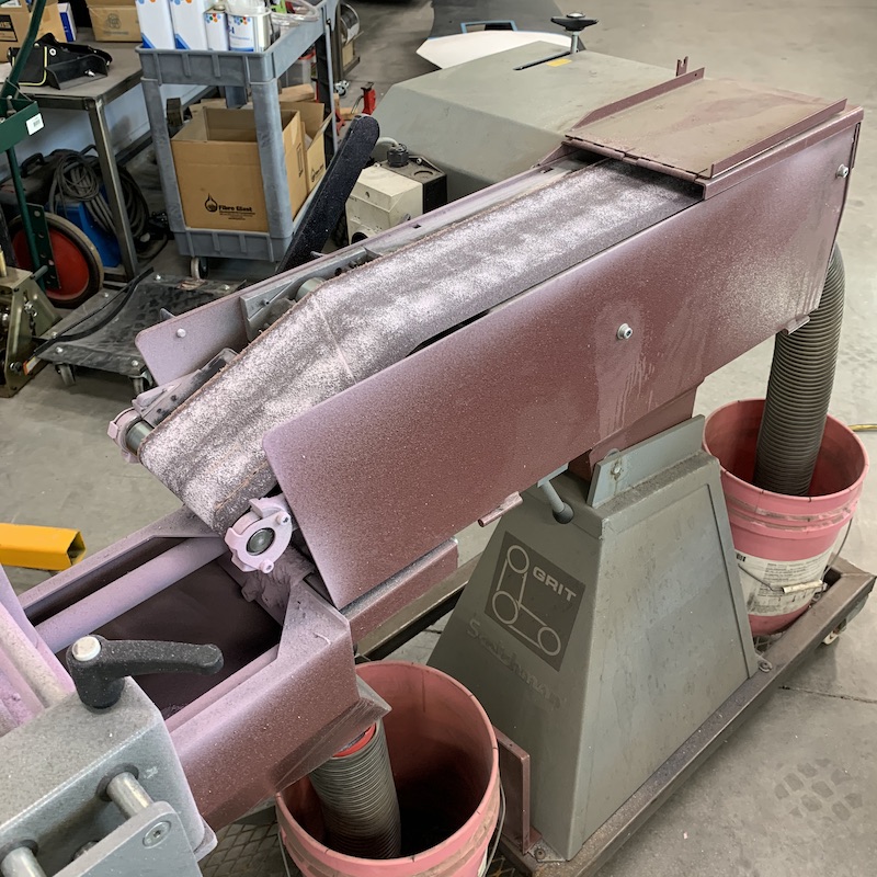
Started out with a practice cut. I want the Lowrance GPS to turn in and face me a little more than flat on the dash. So I made a couple of aluminum templates, Super 77'd them onto the foam and fired up the cutter.

Ya just stick them to the foam.
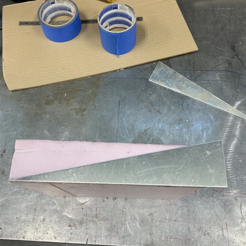
The gouge is where the wire burned into the tips of the bow and went slack. No big deal - this gets glued onto the dash anyhow.
I keep having to tell myself "It doesn't have to be perfect. You're gonna sand and Bondo a bunch."
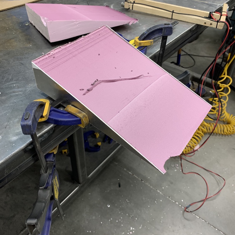
Little more dialing in...
Next was seeing if I was going to be able to make forms that go around the V-brace in the windshield. The dash will go around them and it'll have to pull straight back to come out.
So, once again, fired up the bow with it's new fire proof shoes on and the settings were still too hot. I dipped into the foam like, well, a hot knife through butter - actually more like putting your hand in a bucket of water. I didn't follow the form very well and the wire went red then snapped.
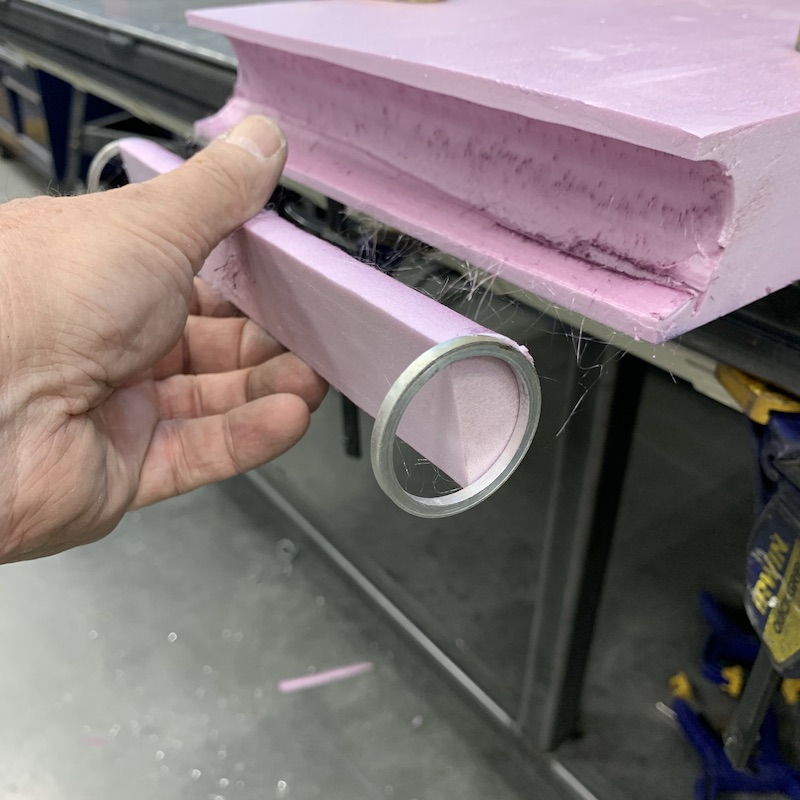
Reset. New wire, turn things down, set wire on test piece and slowly turn things up until wire falls into foam at an appropriate rate and doesn't turn bright red. Perfect. DON'T TOUCH MY DIALS!
Tried the radius cut again - that'll work.
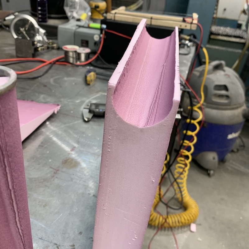
Started the dash sandwiches. The four pieces in the middle of the middle section are all the same with a little blend trimming at the front.
The part behind the display will get cut down a bunch.
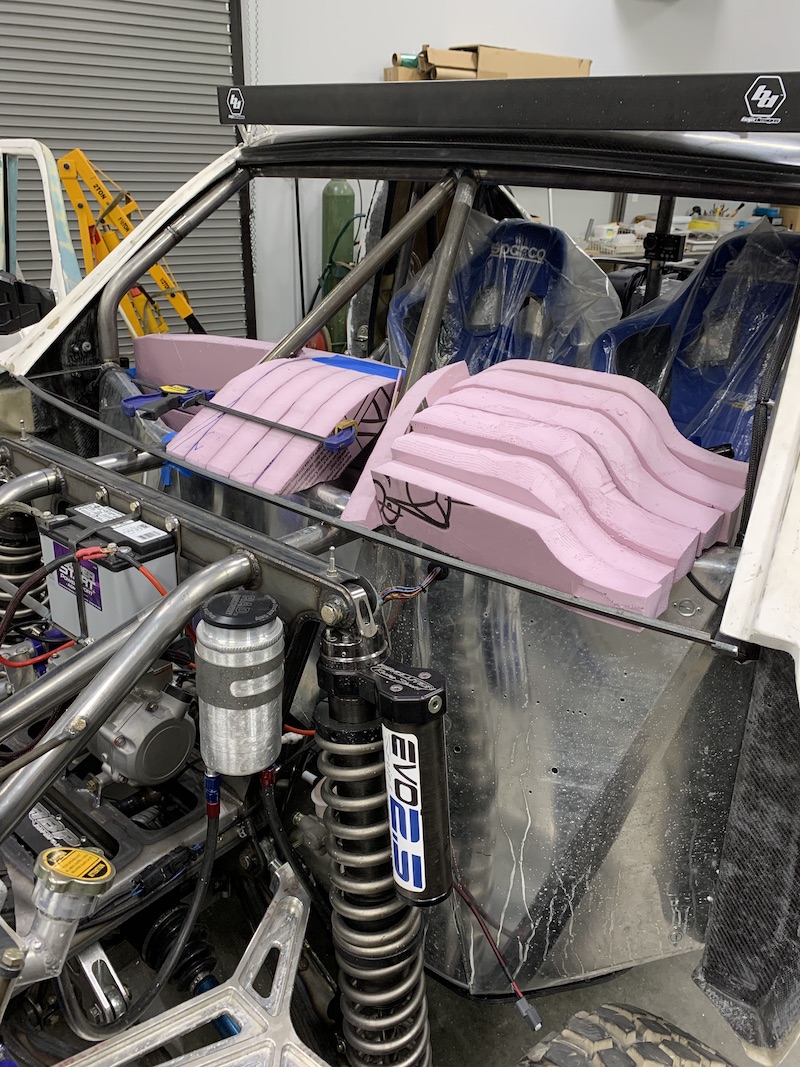
Dash has to pull straight back so the two V-brace notches have to be clocked just right. Finally figured out that a flat plate across the back of both of them put them parallel to the groove's angle. Once I got those in place it was fill in the angled bits.
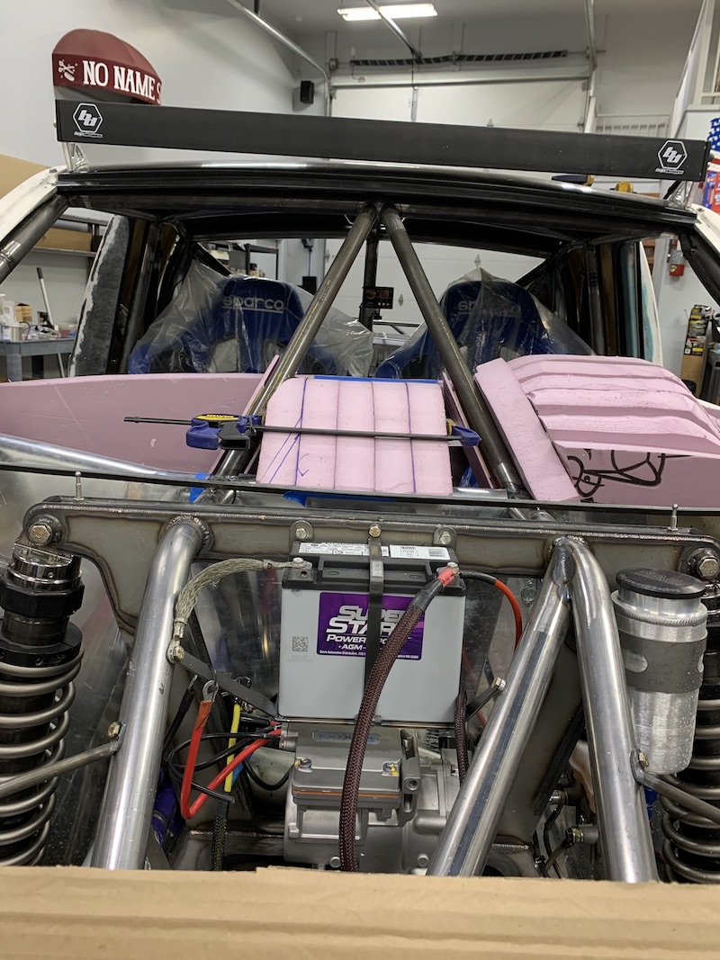
Not even half way in and there's a mess about!
GPS angle piece in place. I'll be adding angled fillers on the three sides that extend out. The whole thing will be nice and smoothly blended.
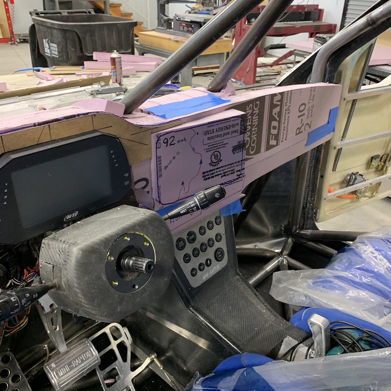
Another view. This side will extend towards the right about 3-4 inches when I'm done blending.
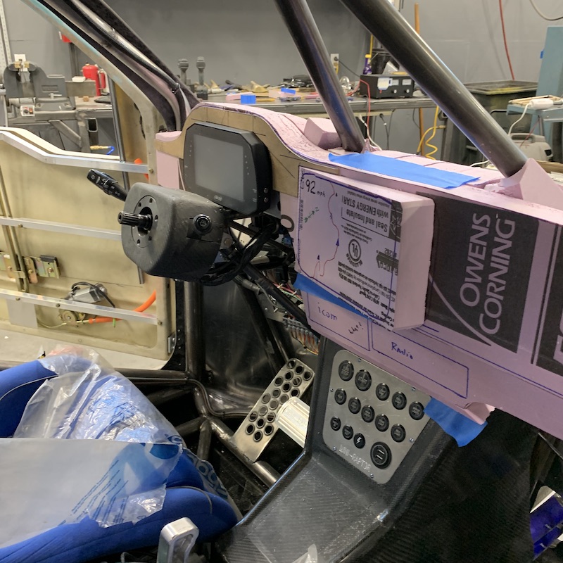
Center section complete and rough sanded.
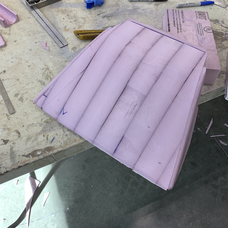
Fits like a non-OJ glove.
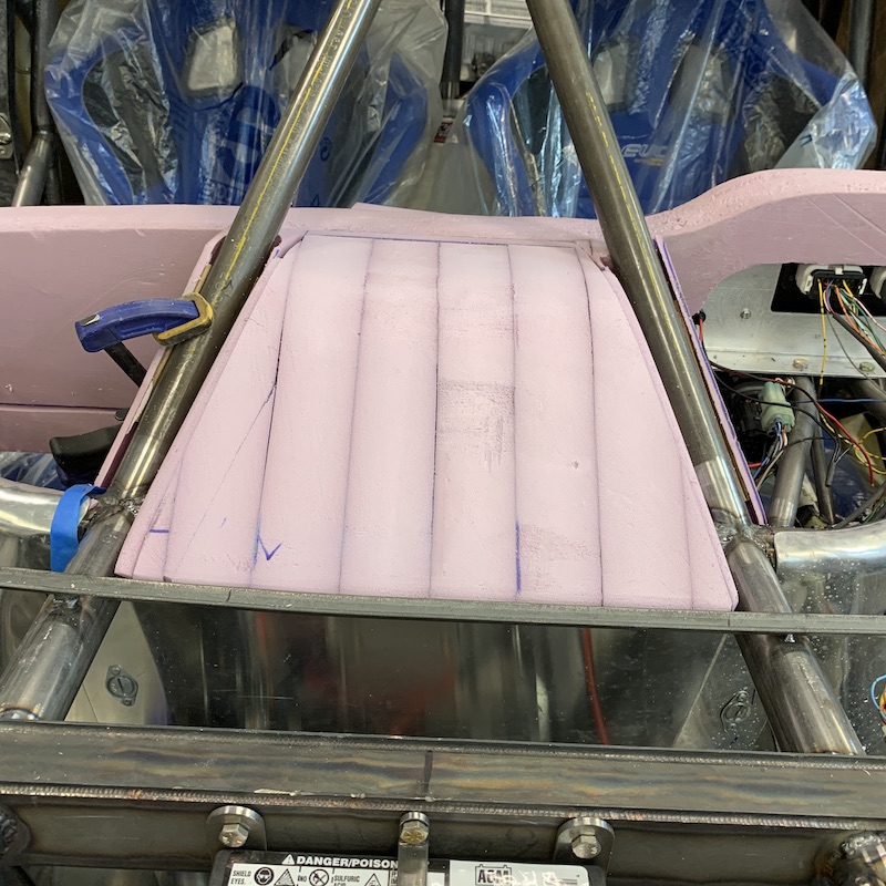
Close up of the fit between the center and the tube piece. The cardboard strips (three of them) are perfect spacers to keep it all centered around the tubes.
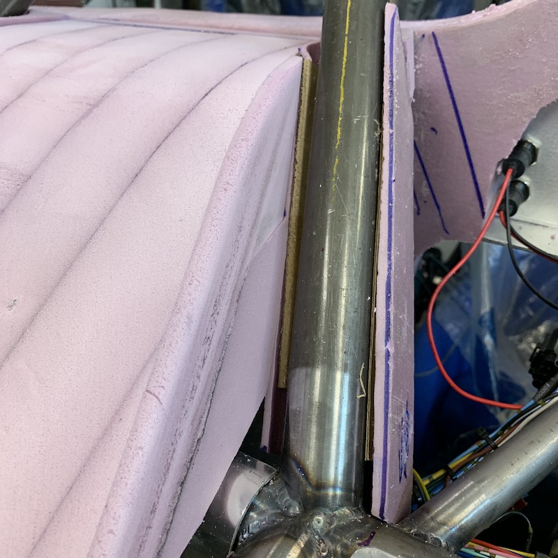
Straight shot of the groove that the bars fit into.

I cannot get over how well the electric carving knife works. Wish I'd known about this 7 years back when I did the RZR dash.
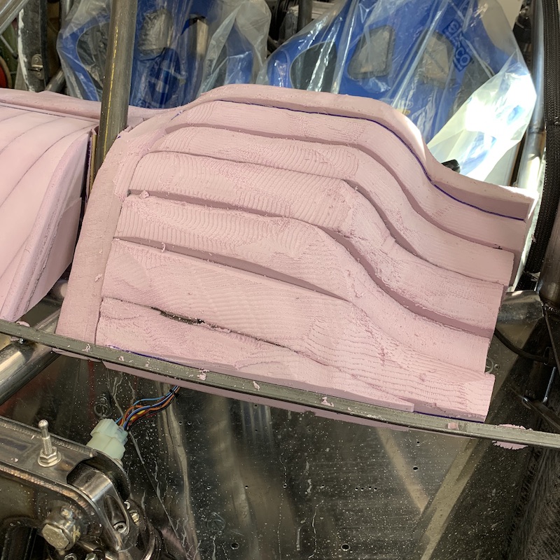
That's it for now.
Wife's taking online night classes - starts in about 10 minutes. I get 4 shop hours this evening.
Jul 13, 2020
jimmyg
Looking great. Let's hope next roast your wife does not roast you over her carving knife.
Me
I'm safe with this one!
The knife came with a pour seat foam kit that I did a year or so ago, not the kitchen. I had the hot wire pulled out and was getting it dialed in when the realization of having the carving knife in house might work.
Climbed up on the bench, pulled down the foam seat kit bucket, took the knife out, did a test run and though "Oh yeah, this is the shit."
I'm impressed how well it works.
jimmyg
PS I Lol at your GPS drawing and the OJ joke.
Me
GPS - total self entertainment. You'd be amazed at the number of little things like that written here and there on the Mini-Raptor.
OJ comment - not sure where it came from. Just popped into my pea brain and tickled me. It's an OLD reference so I wondered who'd get it.
Spent quality time getting the dash's final shaping dialed in and starting on the detail that you'll see from the seats.
The three main sections in the windshield had to get trimmed down a bit to get the line across them to be more consistent/blend better.
This is the three pieces in place but untrimmed. Center section sticks about .500 - .750" (12-18mm) proud of the passenger's side and the driver's part is not shaped quite right and proud relative to the center.
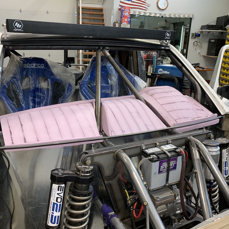
Thought I was doing pretty well until I looked across the dash and saw just how much the three pieces differ.
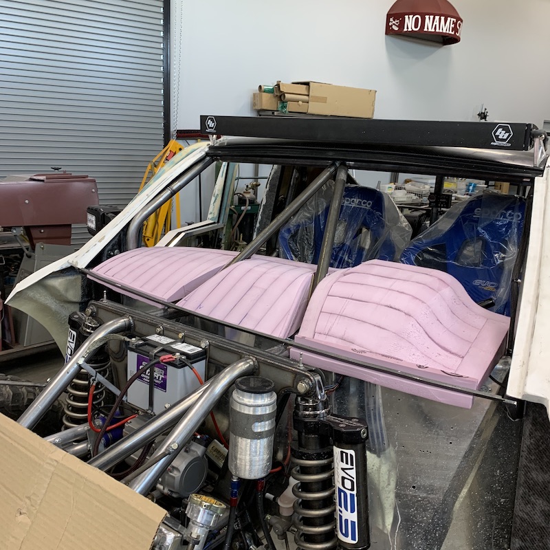
Here, this shows how much better they look with blending. I can lay an edge across the pieces now and they blend pretty well.
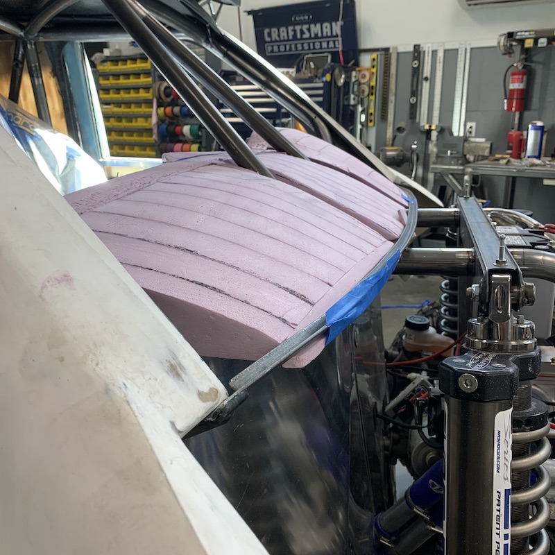
I've also reshaped/removed a bunch of material where the bubble for the AiM dash is. Test fit the windshield (surprisingly it didn't hit anything!) and realized I had more room to make and remove more material for better aesthetics.

Still want to knock out another .500" (12mm) off of the hump and finish the blend from the hump back down to the part next to the door/cabin wall. While it does clear the windshield, it's a tight fit - I'll not be getting my hand down between the windshield and dash to clean the window (even with more clearance).
Also started getting the GPS mount blended in. Added a couple thin strips on top and bottom and the main blend back to the dash on the right side of the mounting pad.
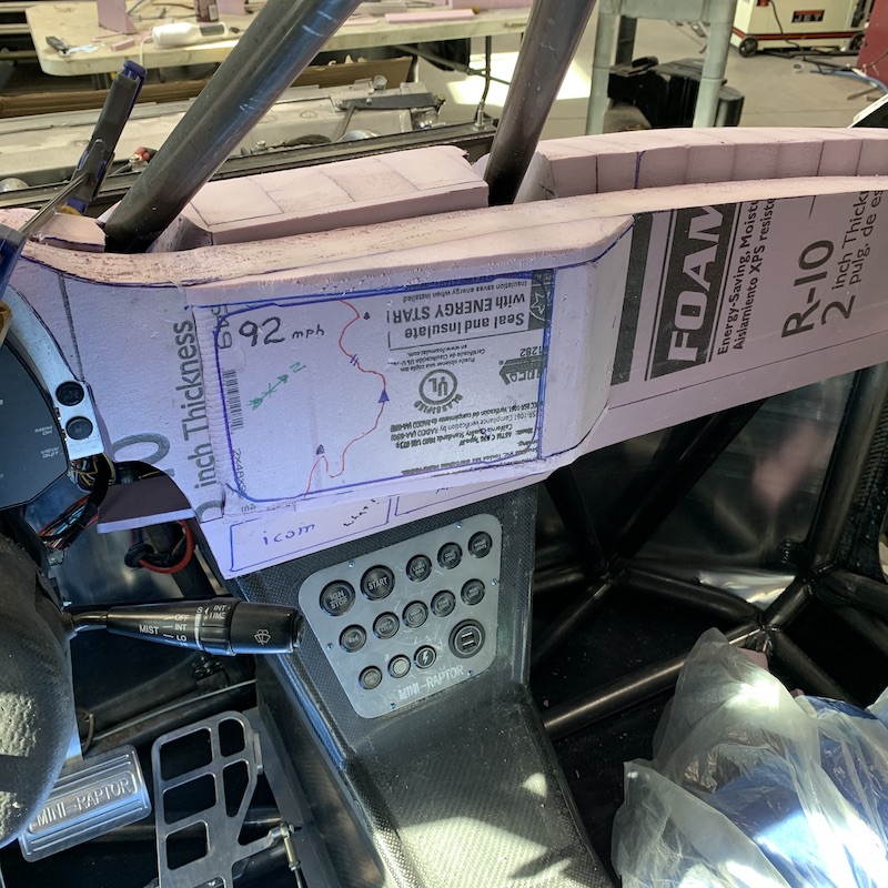
Still have to get the blend between the center console and the upper dash figured out and dialed in. It's more of an abrupt angular change between the two pieces than I was hoping for but oh well, it is what it is (God I've said this too many times building the Mini-Raptor).
Also got the ends of the dash secured to the frame (only have a shot of the driver's side - passenger's side is still in process).
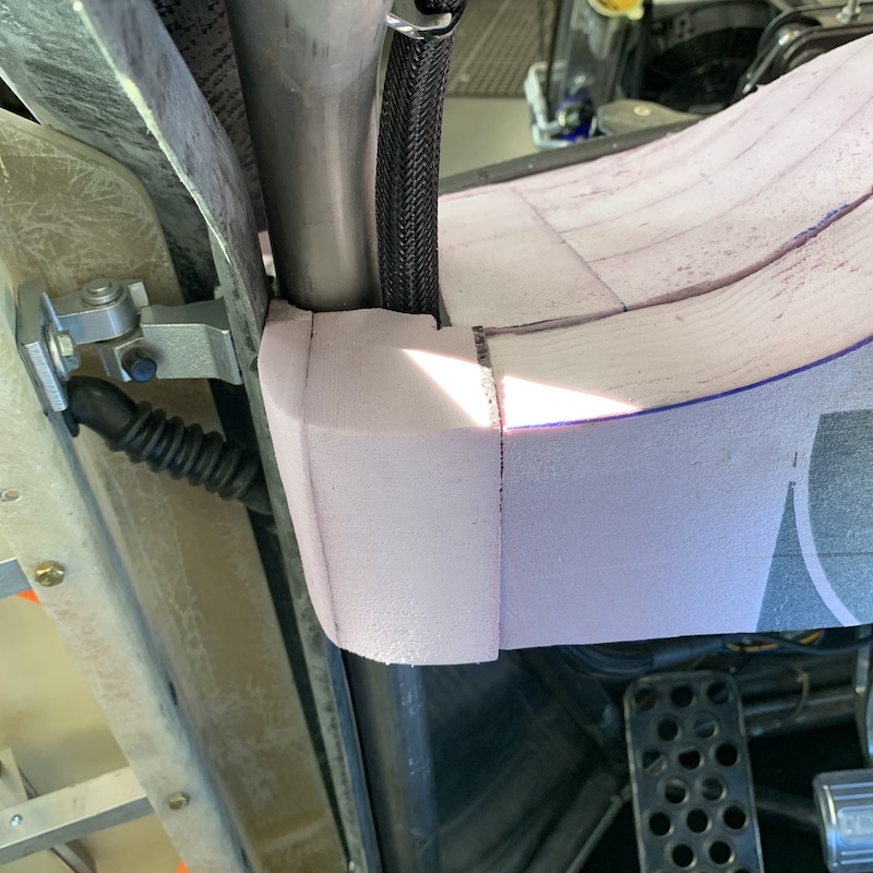
Spent most of yesterday filling gaps, making shit fit more tightly and I'm starting to pin the big pieces together so I can start doing the testing of pulling the dash in/putting it back. I'll have to see what else gets trimmed so it just pulls straight back and comes out.
I also have to start placing the defrosting vents from the Samurai! HVAC system into the two outer dash pieces.
At first I was thinking I'd make this a plug, pull a mold off of the plug, then vacuum infuse the dash in the mold but after the work I've put into this (and I'm not anywhere near being done), I've decided to go the same route I did with the XP900's dash and keep the foam dash and then wrap it in composite.
First, I'm not making more than one dash so making a mold to make more is a moot point. Why have something, make a mold, then make that something again? Nah, I have something, let's use it and skip two processes.
Second, like the first time I did this, the foam makes an awesome mounting material. I can cut holes through it, glue in aluminum sheeting for component mounts and have a nice solid piece that holds everything really well.
I'll make mounting rings and such that will get sunken into the foam and integrated into the final covering with glass & carbon.
It'll also let me integrate mounting tabs/studs and such directly into the dash so when I slide it in, it'll just drop right into mounts and a few nuts will keep it all in place.
Thirdly, once the foam is wrapped it makes for one extremely stiff component. Even with all the compound radius surfaces and blends and such, a composite shell will still be flexy to a point. With the foam in it there's no flex at all. It adds, maybe, 5 lbs keeping the foam in so I'm good with that.
More shop time today. Gotta do a little more detail on the dash pieces and then start working on the front part, blending the dash & center console, finishing up the passengers' end where it goes to the a-pillar, stick the HVAC tubing in and deal with what ever else shows up as I move along.
July 15, 2020
Bullnerd
I don't usually ask stupid questions (muhahahaha!) but can you reach the ignition button strapped in? It looks kinda low, but not the best camera angle.
Me
LOL! Yes, I can reach all the buttons strapped in. Just barely... Damn short people. Now where'd I put my step stool?
Main dash shaping is done. I keep sitting in both seats looking across the dash, finding high spots and area that need attention. I have a 10" x 2" x 1" piece of billet aluminum that has 50 grit (holy shit that eats foam!) and 120 grit strips of sandpaper glued to it. It does a really good job of removing high spots and blending large areas.
I'll get it covered in pink dust and then use the wrong side 'cause I can't tell which side is which just with a glance. This tends to lead to having to sand a lot more down than planned. Like I said, the 50 grit does some serious damage if not handled carefully.
Dash a couple of days ago. Notice the gap on the left side of the dash bubble, the three pieces don't line up smoothly with the main strip that goes across the cabin, there are high and low spots:
Dash last night just before I walked out of the shop.
If you look carefully you'll see the area in front of the passenger's been knocked down and leveled a tad and the driver's side area's had quite a bit more sanding and detailing. There's blending along the top of the main piece and such.
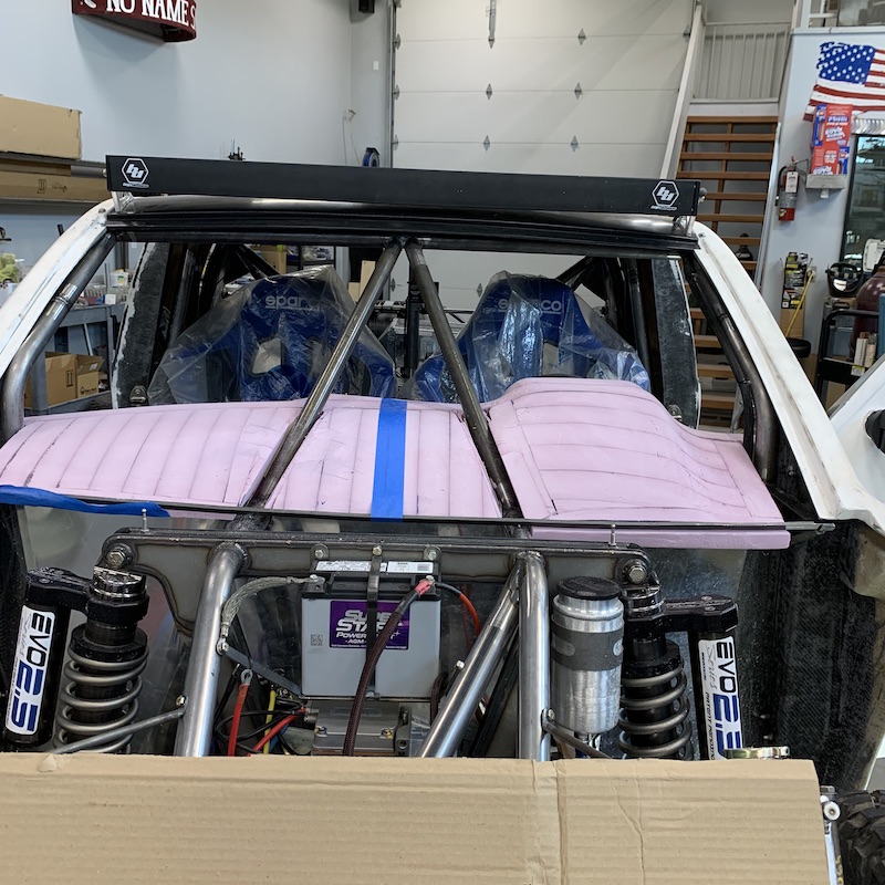
I like working with the foam because if there's a low spot I just take a piece of thin tossed out stuff, spray a little Super77 on both surfaces, stick 'em together and sand away. You can see where I filled a dip in on both the passenger's and center sections by the V-bars.
This shows where I've worked on getting all three pieces more or less in the same plane as each other where they go around the V-bars.
Here's the cockpit detailing. Made a sun visor for the AiM dash, left rooms to get to the buttons. I've also made a stepped shelf for the intercom and radio - they'll sit back and under the GPS, above all the switches. I thought I got a passenger's side shot but I don't find it in my phone.
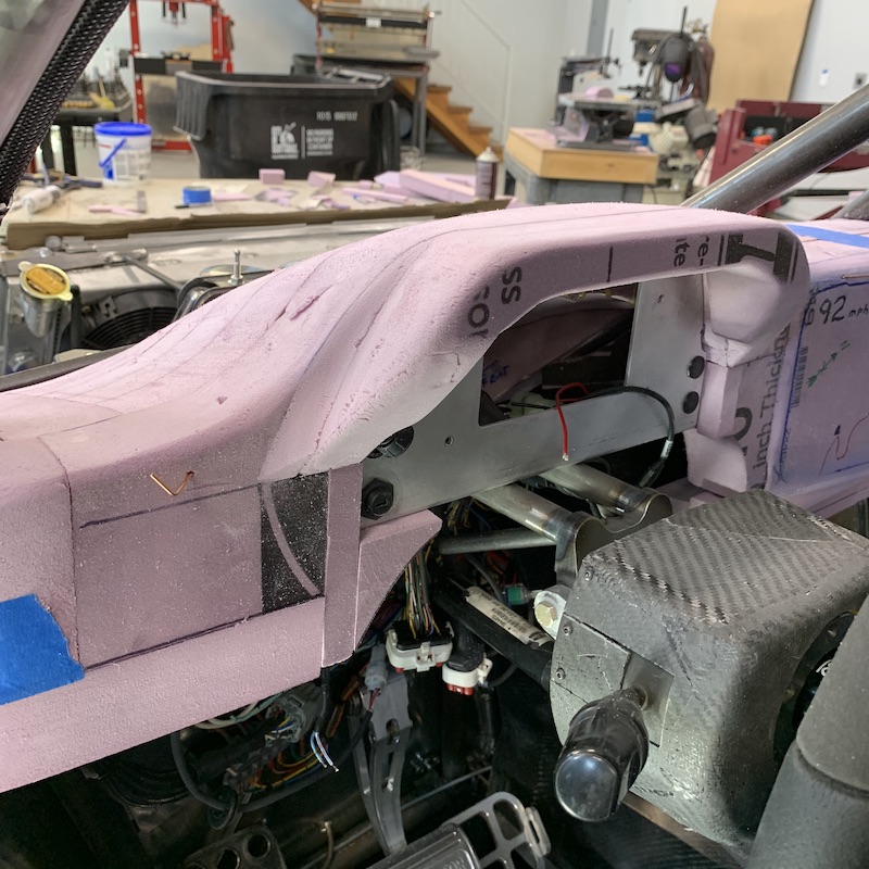
Dash is all glued together (did this the late part of yesterday). Hopefully it'll pull out without much fighting. I'm really curious to see if it's going to just come right out as planned (yeah, like that's gonna happen!) or if it's gonna require trimming and such.
Since I've decided to go ahead and do like I did on the XP900's dash, and wrap this core instead of making a mold, I'll have to go back into the back/underside and add a bunch of support and filler so that when I put the vacuum bag on it the dash doesn't collapse.
Gee, wonder where I figured this out? Good ol' experience will keep me from letting certain things rear their ugly heads again.
I iz smarter dis time!
Once out I'll match the level of the three pieces to each other, especially around where the V-bars enter the dash. The foam is still proud around those spots - can't run a flat sanding bar over the big slots w/the bars in place.
Hopefully I'll get the dash all sanded down and detailed today and throw some drywall mud on it to fill in cracks & crannies and then it'll be time for the first layer of really light fiberglass cloth. Once that's on, it'll be more sanding, blending and such and then more layers of fiberglass, repeat until satisfied. Once that's all done it'll be time for two or three layers of carbon fiber and vacuum bagging time.
Since my first round with vacuum infusion worked and I know what I did wrong, this should go better. I'll get all the composite stuck down with Super77, get it all under vacuum and then introduce the resin. HOPEFULLY things work out. I'd love it if I can get to that point next week sometime.
TheDoc
Get the sexy carbon weave with the coloured thread in it, blue, red, or gold I think. Make that puppy shine...
Me
Like this?
This is custom 12 string that my buddy, VooDude, the guitar maker did:
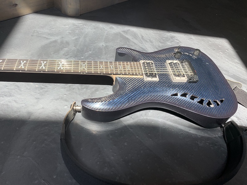
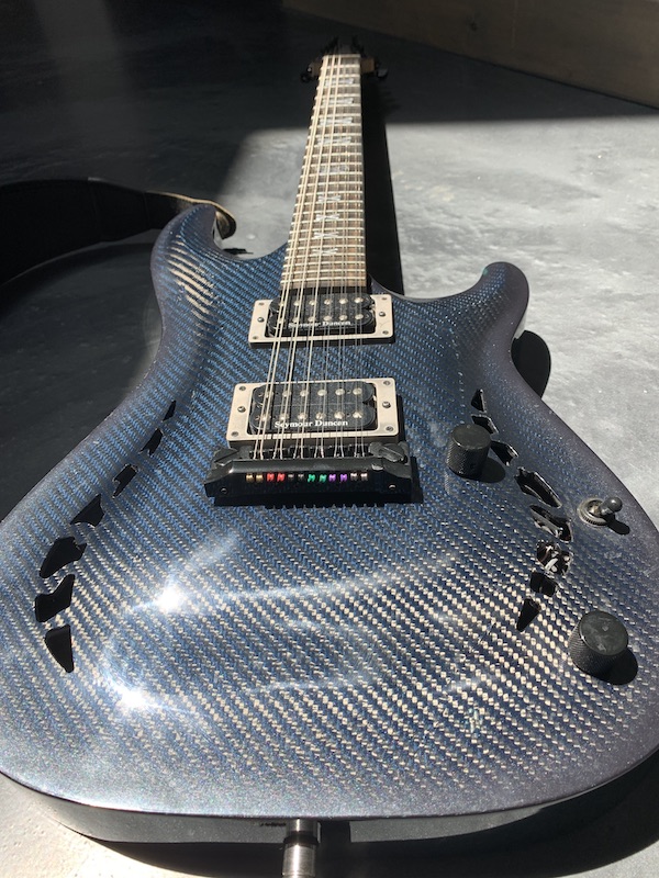
I wish I could still source it. Used to be able to get red, yellow, blue (and maybe orange?) from Fibreglast but they don't carry it anymore.
Jul 16, 2020
Yesterday's work was
A) Rather pleasant. Just cruised along and didn't have any issues other than sticky fingers from Super 77 usage. Didn't bleed.
2) Satisfying - it fits, it comes out like it's supposed to and it didn't make me swear whilst working on it.
III) Made me feel pretty confident about doing this dash. I've got a clue this time and I keep going back and rereading my dash build on the old RZR I had and seeing what I did wrong.
It came out of the Mini-Raptor with minimal argument. The center piece between the two V-bars was tight. It's impressive how quickly two triangles will wedge themselves together. Still, it came out in one complete, still stuck together piece.
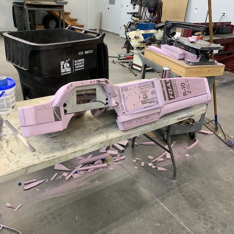
The two channels that the V-bars go through have definitely been the tricky pieces to get in and then get clearanced well enough that the dash slips in/out without fighting.
Here they are after first removal - tight, squeaky (hate that styrofoam squeak - makes goose bumps like nails on a chalkboard) and the center section flexed down quite a bit.

Dash with 95% of the rough sanding done. Notice how much more the two grooves have been opened up to allow the dash to be inserted/removed. It slides right in place and darned near clips in now:
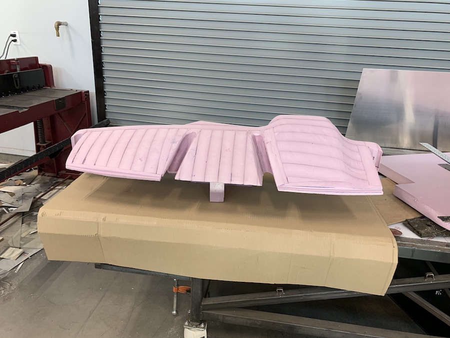
Another shot. I spent quite a bit of time sanding the main bubble around the AiM dash area flattened out, lowered and blended to follow the main line of the rest of the pieces.
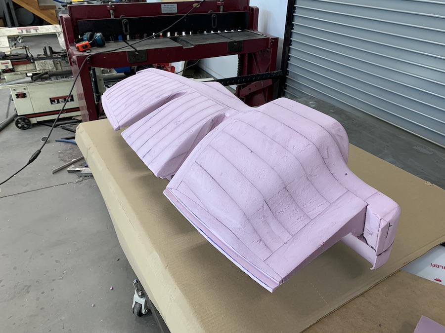
Front shots showing a bit of the detail around the AiM dash and the recesses that the radio and intercom will go into.

I still need to get a blend strip between the bottom of the GPS and the top of the section above the two electronics. I'll stick a little fillet wedge in that corner and sand until smooth.
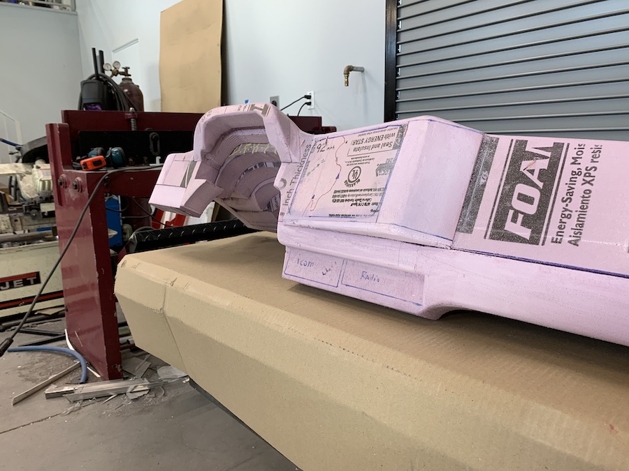
I also need to do some detail work around the bottom ends of the slots. One of them's got both of the horizontal fillers in it and I need to add those to the other side and then cut the whole bottom flat/flush. The ends also still need some shaping done.
I'll finish the detail work/fillers and such and then start skim coating it with drywall mud and work on getting thing smooth and ready for the first layer of epoxy resin and 1oz fiberglass cloth just to shore everything up. After that's on, it'll be more filling, sanding, priming. Once all is where I want it, I'll go into the main layers (probably two or three of 4 oz fiberglass cloth and at least two layers of carbon).
But, before I do any composite material laying I'll be filling in the back side of the dash with expanding foam and making the thing one solid, seamless piece. When I pulled a vacuum on the RZR's dash, it crumpled in a couple of spots where I had large voids and a couple of air pockets. This time I'll make sure it's solid through out so I don't get warping and such.
More sanding today!
Yay...
Jul 19, 2020
Dash is pretty much done and waiting on materials. I'll skim coat it with drywall mud one more time, give it a sanding, then once I have materials in, I'll bag one layer of light fiberglass in place with epoxy.
To keep things in place, I've made aluminum mounting rings. These will get 4mm nut rivets installed after they get glassed into the part.
Lowrance GPS gets sunk about half the depth of the face plate into the dash. Looks better than just sitting on it.
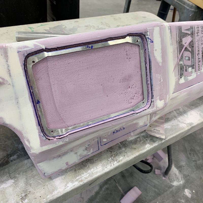
When I pull a vacuum on it, to keep things from flexing and puckering and such I've made a plate that will take up the largish airspace where the GPS fits. This works well - have done it before.
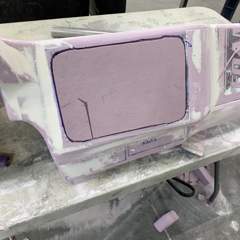
Radio mount will double as both a radio holder and as a mount between the dash and the center console. This, too, gets glassed in.
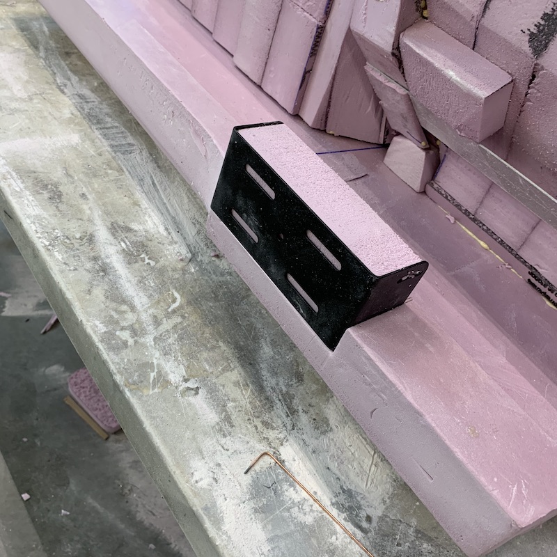
Here's the mounting ring for the intercom. Once I looked at it I realized it's flush - the intercom needs to be flush so the ring gets sunk another 2mm or so.
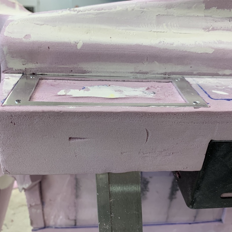
All the mounts in place.
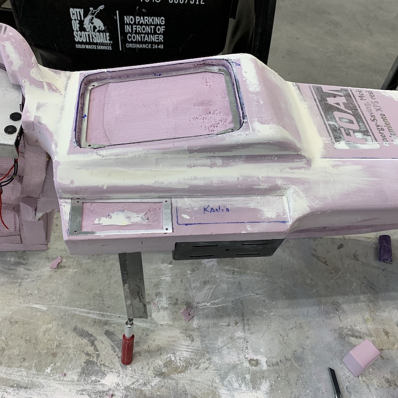
Dash sitting in layer number three, I think. Still have sanding and filling one more round before first layer of glass.
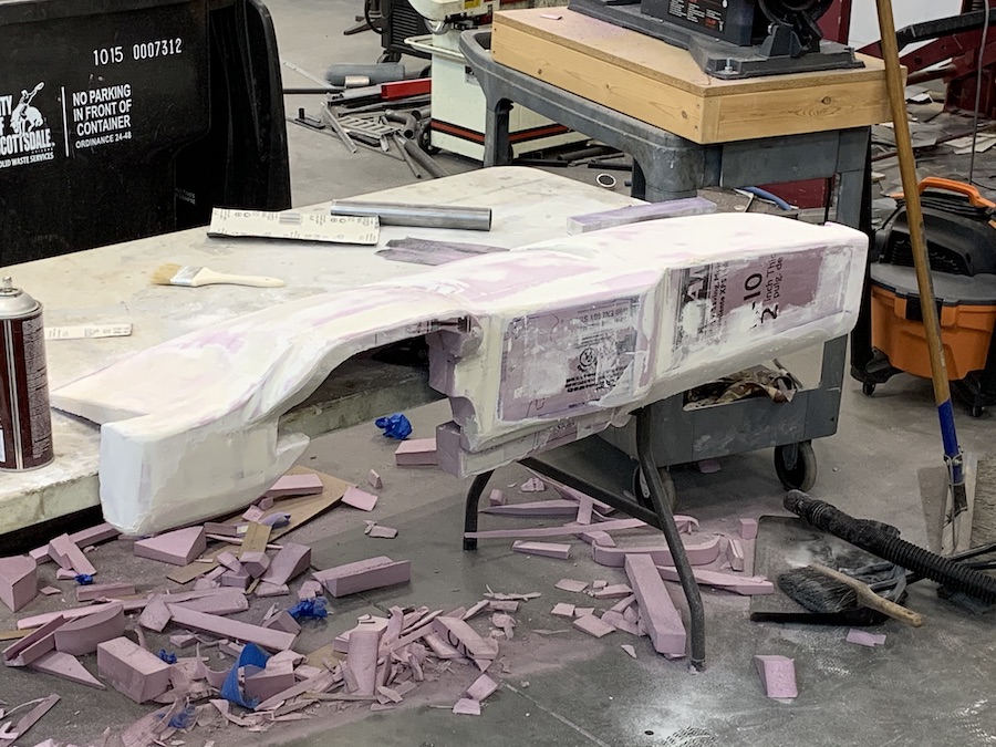
Dash in its home.
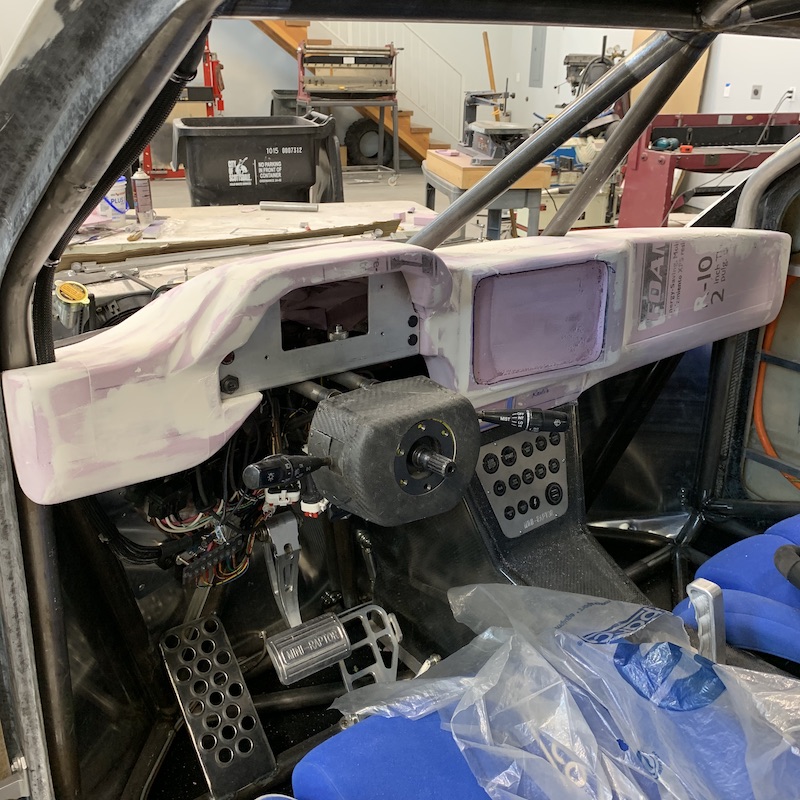
While I wait on stuff for the dash I've started on the rear tail lights. They're gonna be composite. I'll get these done and then tackle the headlights.
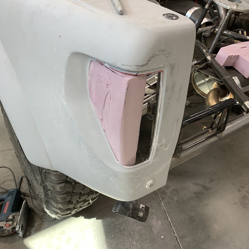
Jul 21, 2020
Got some progress on the rear tail light housing done yesterday. Running light fitted (sequences yellow when signal is activated) around the perimeter of the tail light window. It's being held in with the foam and the back side of the foam is shaped to make the mold for the housing.
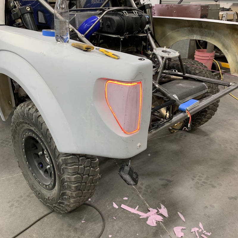
Here's where it's gonna get fun...
See the groove? The LED strip sits in that. Hopefully...
I'm going to stuff two layers of carbon cloth and the LED strip down into that groove, capturing the LED strip in a carbon u-channel. Then I'll cover the rest of the foam in carbon cloth, bag and infuse and (hopefully) form the carbon housing.
The Rigid Chase light that I'm using for signals/running/brakes will get mounted inside the carbon cover (actually will mount the cover to the light mount) and the cover will also be held in with the screws that will hold the lens in place. The Chase light isn't a bad looking piece, it's black and it's gonna be behind a lens so hopefully it just sort of blends into the housing. It is what it is (or will be what it will be? - isn't that a Zeppelin song?)
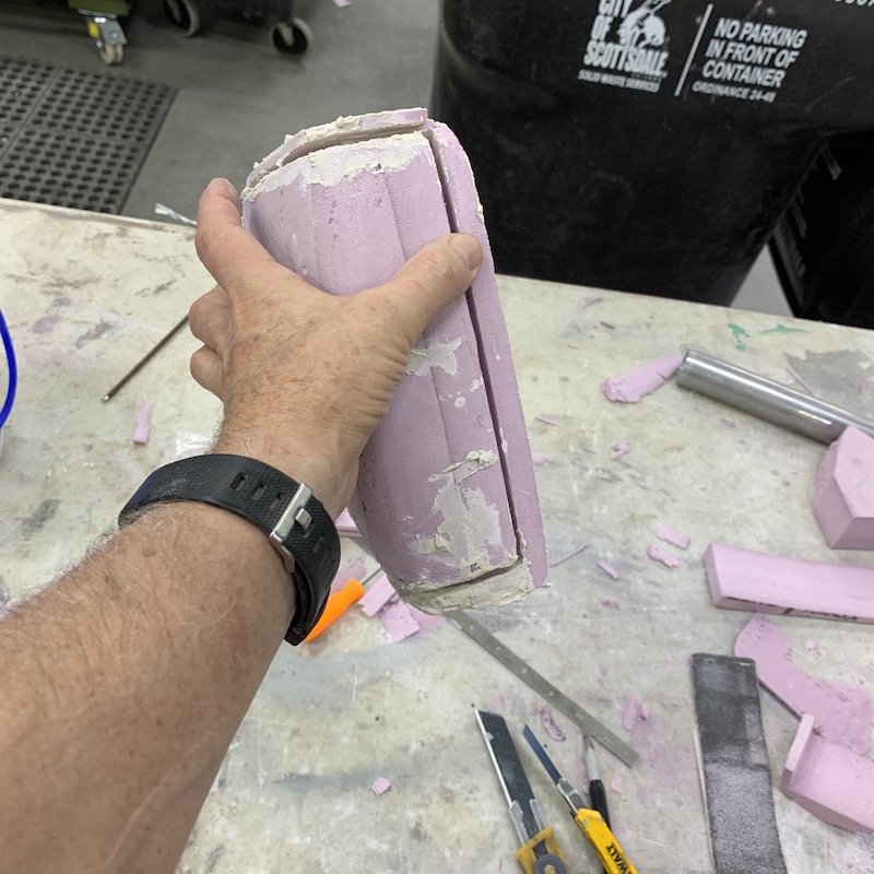
Here's the shape of the housing. Gotta get a couple more layers of mud down, shore up a few spots and then it's skim with Bondo, sand, prime, sand, sand, sand, and hopefully have a ready to go plug.

Everyone's gonna be happy too - I have to pull the foam outta this.
Jul 22, 2020
No pix today - dirty hands.
I hate sanding.
First couple rounds of Bondo kicked really quickly yesterday evening. Scraped off what I could and then did a bunch of sanding to remove the rest of the lumpy stuff.
Second try with the Bondo, today, was better - and because it's setting so quickly, I'm doing sections. Build a lip, smear a hole, sanded in 20 and ready for the next section. It's moving along.
I hate sanding...
Have to massage the LED groove a little more (filled it with epoxy and will level/cup the bottom), prime the plug and, you guessed it, sand more. I'll get a couple coats of primer down, then the mold release layer stuff and it'll be vacuum bagging time. Hopefully tomorrow?
Walked past the dash and looked at it for a moment. Been sanding a football sized piece for two days. That dash is gonna take a while.
I hate sanding.
Jul 24, 2020
First tail light pod is now primed and ready for more (yeah, you guessed it) SANDING... Gonna sand it smooth, fill in more spots, prime again and repeat until my little pod is nice, smooth and shiny.
I'm impressed with just how much primer brings out all the bad spots, what you've missed, etc.. I do admit to not getting the first couple of layers on well. Been a while since I've used a spray gun, didn't have it set quite right, was trying to get down into the grooves - yeah, made a mess. Oh well, I can fix it (by sanding).
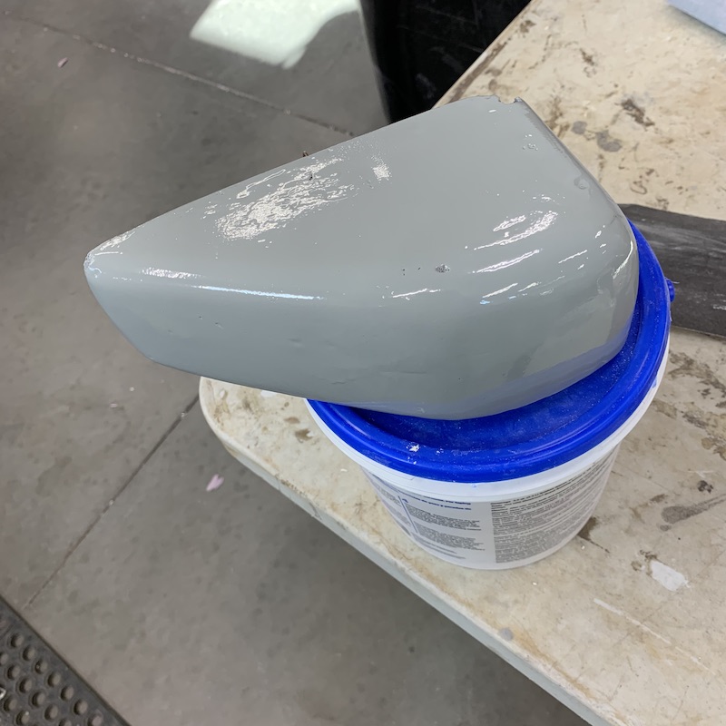
Here's the part that will face out. The lip around the edge is what gets adhered to the inside of the bed side so the slightly crusty stuff gets hidden. The center section, that's not fully sprayed/covered, gets removed after the carbon's been put down. The body center's been retained as support when I put the vacuum on it. No support and the thing will collapse on itself.
The LED strip groove turned out pretty nicely. Still have sanding and smoothing to do. I'm not overly concerned about the looks of it as it's gonna be hidden within the whole unit and you'll not be able to see that part.
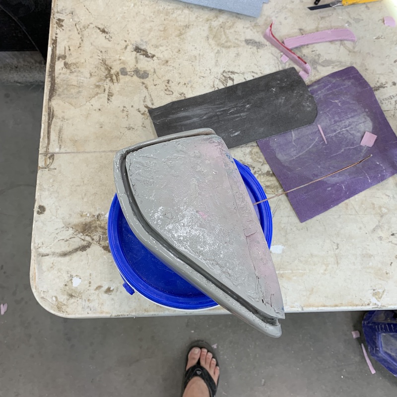
While the primer was drying I got to work on the other side. Gonna get it all formed, covered and primed so when it is time to do the carbon cover work I'll have both pieces ready to go.
I think I'm going to try a soldering iron with a custom (beaten into the correct shape, with a depth stop) tip for cutting the groove this time. On the first pod I tried a Dremel and all it did was make a mess. It had a problem with it heating up, sticking to the foam and then melting the groove. Made a mess, made the groove too wide, didn't work well. If I can get the soldering iron to work I'll be able to use the window in the fender as a guide.
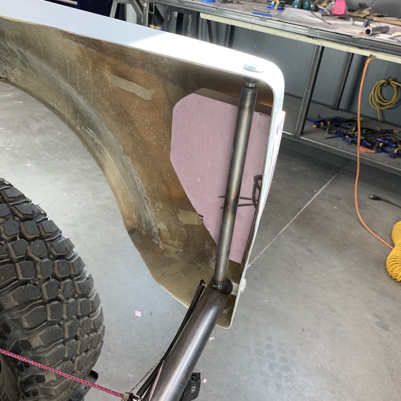
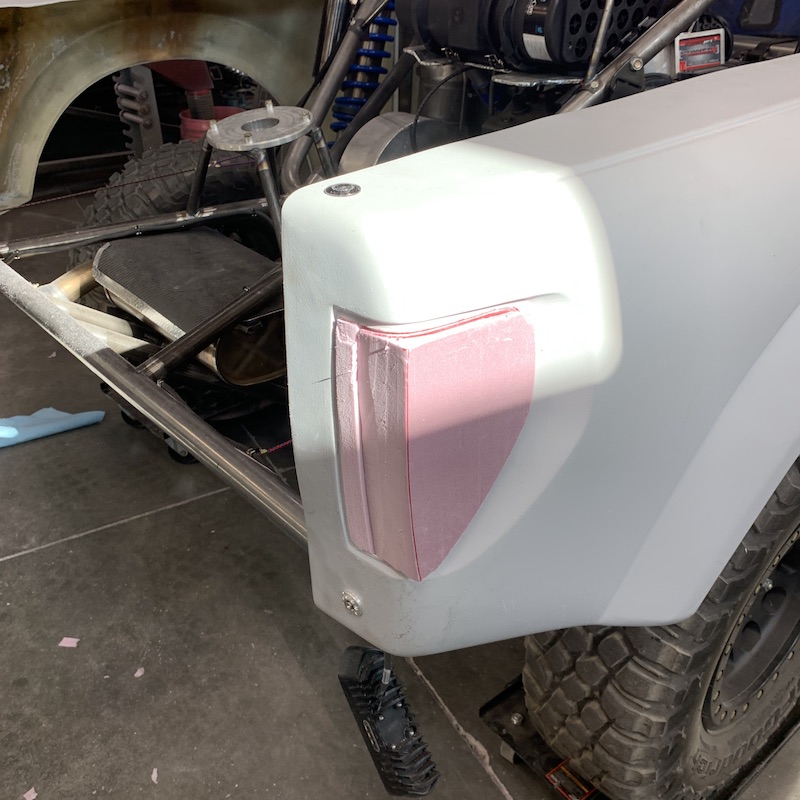
Gratuitous shot of the sunrise from a couple of mornings. Gotta post something pretty to look at besides Mini-Raptor stuff, right?

Jul 27, 2020
Decided to try and get both of the rear tail light pods to the same point of completion so I'm presently shaping the other tail light pod.
I got fancy this time trying to cut the groove - modified the end of a soldering iron to cut the groove. Worked really well and gave me a pretty decent, clean groove.
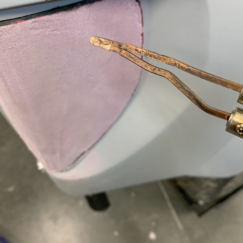
Pod on the left still needs more primer and sanding. Pod on right needs everything. Got the shaping close, will cover in dry wall mud first, level and then start with the Bondo. I'll get it all covered and then go about priming and sanding both until they're where I want them.
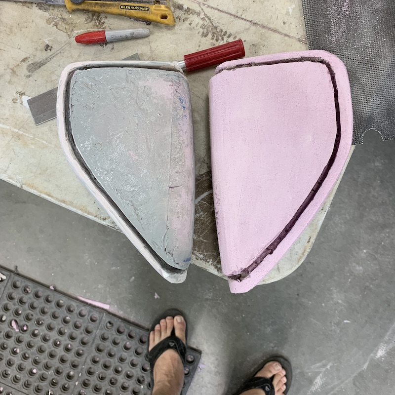
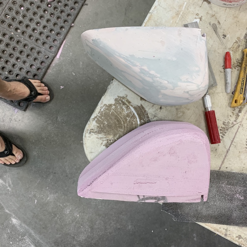
So as I've been working along I'm realizing that I need to do all the foam work first, then get things primed then bagged and vacuumed. One mess at a time. This means that I'll be working on new headlight pods next and I need to go find another sheet of pink foam and make inside door panels.
Anyhow, I did two jobs today, kinda intertwining them. The tail light pods are ready for primer (almost - one needs a small chip attended to) and I've tried something new.
Tail light pod covered in Bondo pre-sanding: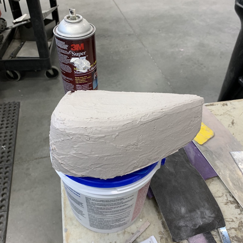
Both pods ready for primer:
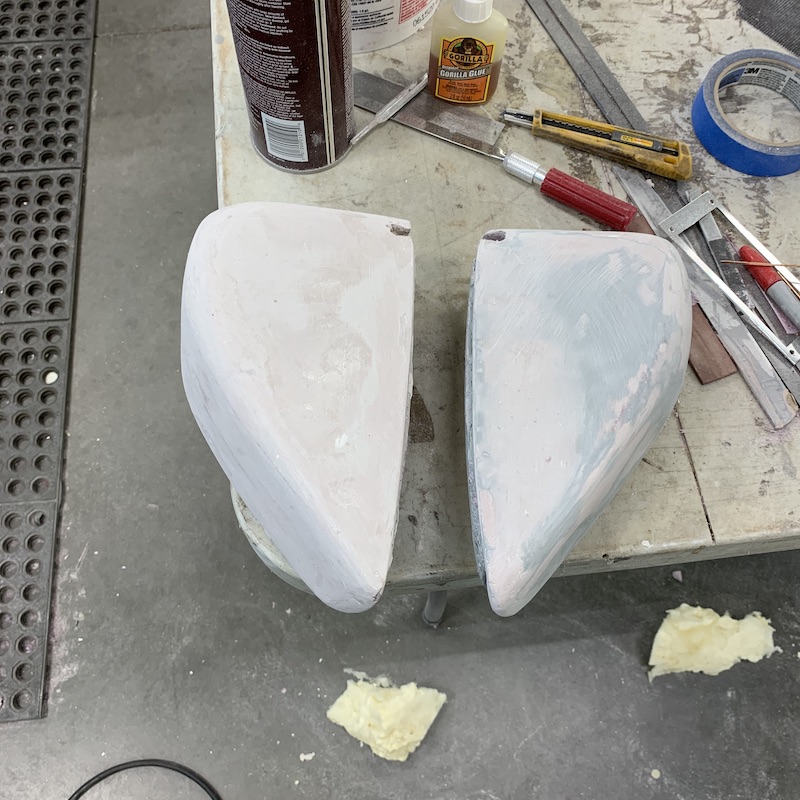
While I was waiting on layers of Bondo to dry I gave two part foam a try. I've played with insulation foam before so I've a bit of an idea of how it fills and such but this stuff is industrial and fun!
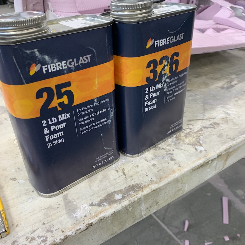
I figured that mixing four ounces was probably a good start. The stuff starts setting up in about 45-60 seconds. Pour two oz, pour two oz, stirrrrr and start sloping on. I made sure that my first pour was careful and what I thought was light into the cracks and crevasses in the dash. As it dried it pushed the dash around a little bit - I kinda fought back until it hardened up. It doesn't take long for it to set.
First pour:
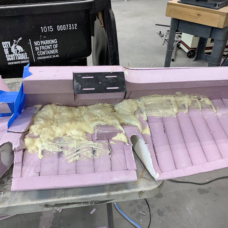
This is four pours:
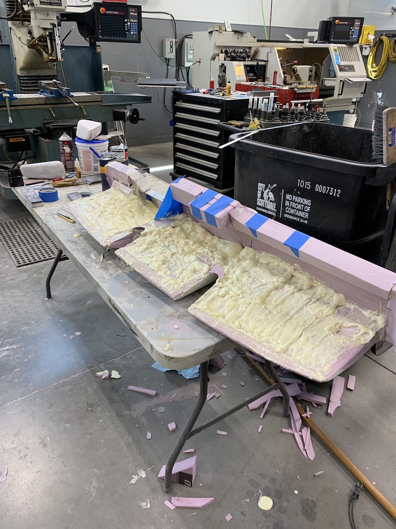
After I got the fourth pour down I started sanding - I thought it was going too be more like the pink foam. Nope, it's more like plastic.
I had a lot of over pour (the stuff just keeps growing!) and since it was hard I thought that a right angle grinder with a flapper wheel would be good. Yeah, it works but man, oh man, it covers you with this dust that's sand grain sized yet light. Nasty.
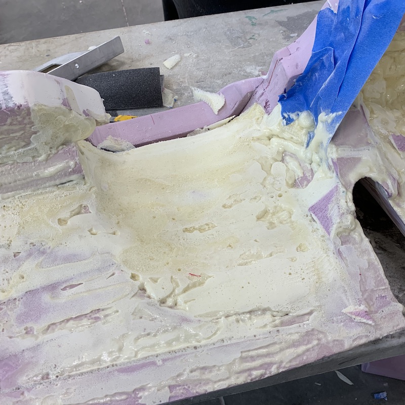
The fit is tight enough that I had to do clearance sanding across the dash - you can see the arced mark.
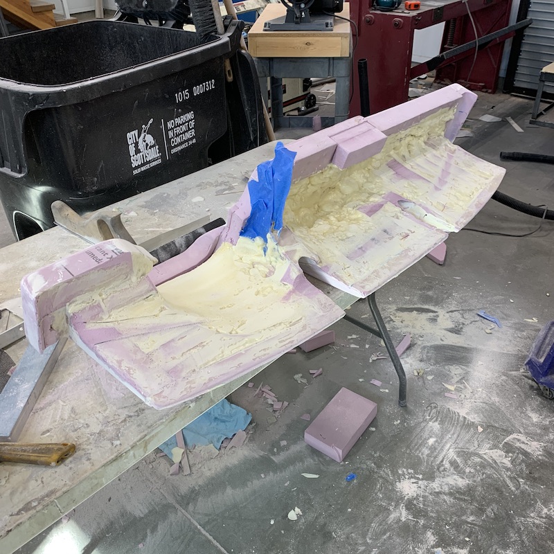
I found that the stuff trims fairly easily before it fully sets up. It goes from a foamy liquid in a cup to something like angel food cake batter but sticky as Hell. After about 4-5 minutes the foam starts setting and it goes to a spongy, but still sticky state. Another couple of minutes and it goes to a dry sponge - this is when the electric carving knife was golden.
I'd filled the cavity that's behind the front of the dash up (with way too much) and was able to trim it off before it got out of hand.
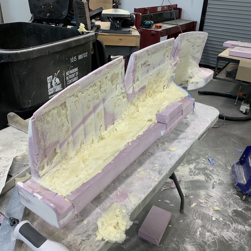
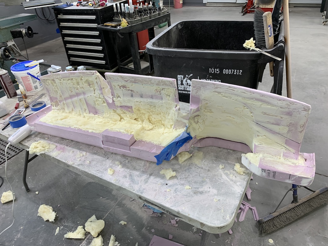
The filling of the dash has served a couple of purposes:
Stiffens it up big time
Sticks it all together - no more floppy pieces
Will keep it from collapsing when I vacuum bag it. I learned this from the RZR dash of years ago.
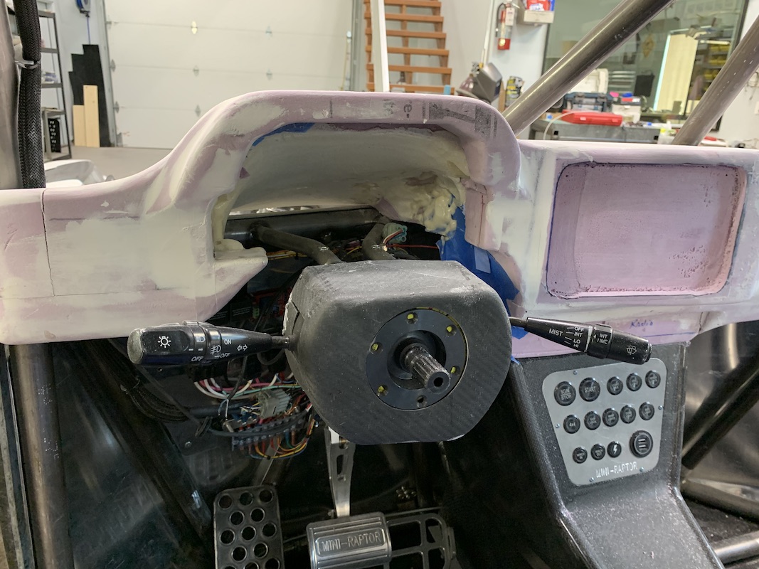
I'll clean up the back side a bit more - not a lot or reason to do so and I have one more pour to form a corner I want integrated between the dash and the center console.
Two part foam is fun! Interesting stuff... May have to see if I can pour a headlight.
Jul 28, 2020
kustomfab2003
Whats the difference between the poured foam and say what you get from the hardware store in a can (expanding foam)? Are the molecules a bit more tighter when cut? More volume when mixed...?
Me
Good question. Not sure I can answer with "engineering details" but I'll give it a shot.
Foam in a bottle (Great Stuff) doesn't seem to have any strength, stays light, airy and a little on the softer side of things (like styrofoam). I can't find any specs on Dupont's web site about the physical properties of Great Stuff.
I don't know how it does against things like epoxy and poly resin - don't recall having issues when I've used it as a filler.
"Tack-free in 5-15 minutes; trims in one hour" Sounds similar to the two part stuff. Not really sure how long it took before the two part stuff was "hard", as I wasn't clock watching. I do know that the two part stuff was stiff enough to trim out big chunks after about 10-15 minutes and just got harder as time moved by.
The two part stuff is more like a plastic once hardened. I'm curious to see what close to 24 hours of hardening time has done to it. The stuff is impervious petroleum products.
Check the little details box under the delivery van icon: 2lb-Mix-And-Pour-Foam/Mix-and-Pour-Foam
Interesting (reading stuff as I find it) - it'll take less to squish it (34 psi) than to pull it apart (52 psi).
Stuff in a can is more like spreading growing whipped cream. It comes out foamy, stays foamy and grows.
The two part stuff starts as a liquid that has the viscosity of thin motor oil (actually kinda looks like motor oil) so it seeps down into seams and cracks and such. It goes in a dark amber colored liquid and then starts turning into a lighter amber foam and pushes your stuff apart if you're not ready for it. "The foam will exert approximately 2-4 PSI expansion pressure during void fill; for a completely closed mold, expansion pressure can reach 4-6 PSI." Yeah, I saw that on the dash in a couple spots.
The stuff's pretty cool - I can see how one could get very creative with it making plugs and molds.
Jul 28, 2020
Foaming in the dash is done. It's all trimmed up and I'm starting to cover the whole thing in a light skim of drywall mud.
Started out the day in grit. Cut down and smoothed out the areas I was after with the flapper wheel. This is the shit it covers you with:
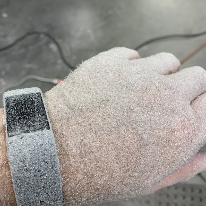
I'd had enough with the mess, pink and amber dust all over EVERYTHING, pieces of cut foam all over the floor, crap everywhere. It got to me and I spent about two hours with the blow gun attachment, broom and vacuum cleaner making my world a workable place again.
After getting it cleaned up I wanted to try the suggested putting something on it to make the surface smooth idea - so I used waxed paper and it worked pretty well.
Here's the first step - 2 oz of this:
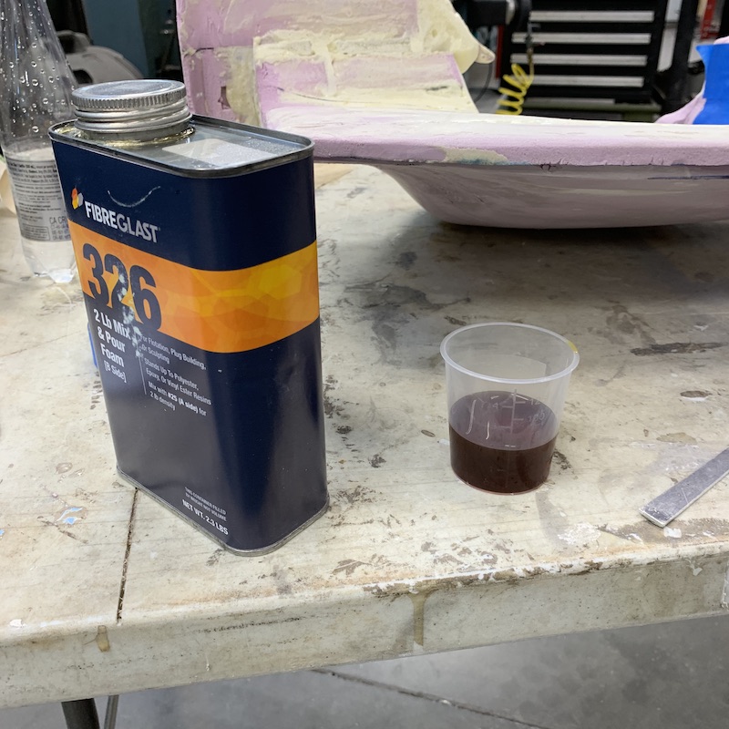
Mixed with two oz of the other stuff and stir. No pix of the other stuff - time crunch. Still can't believe I didn't get anything on my phone doing this...
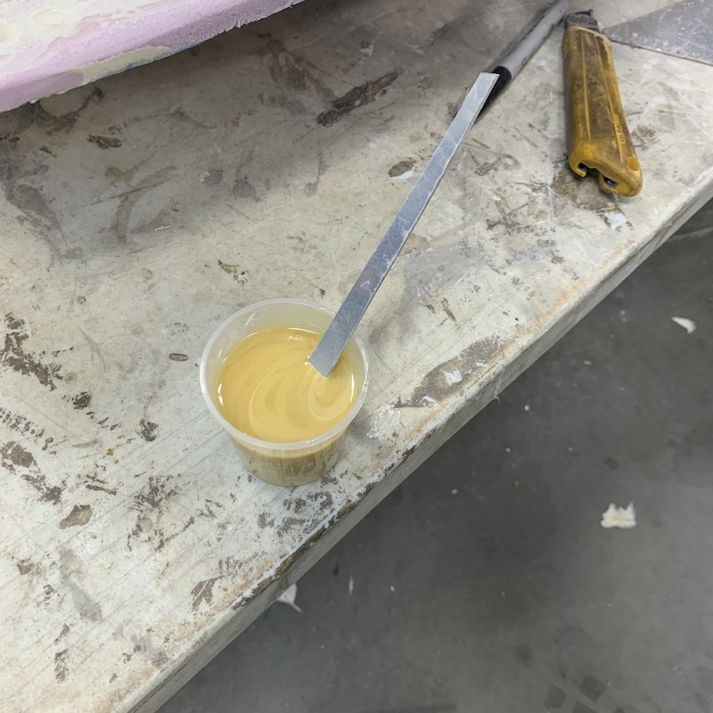
Pour in place and watch it grow. It's kinda funny - after it's done it still sits there and ticks and pops and creaks.
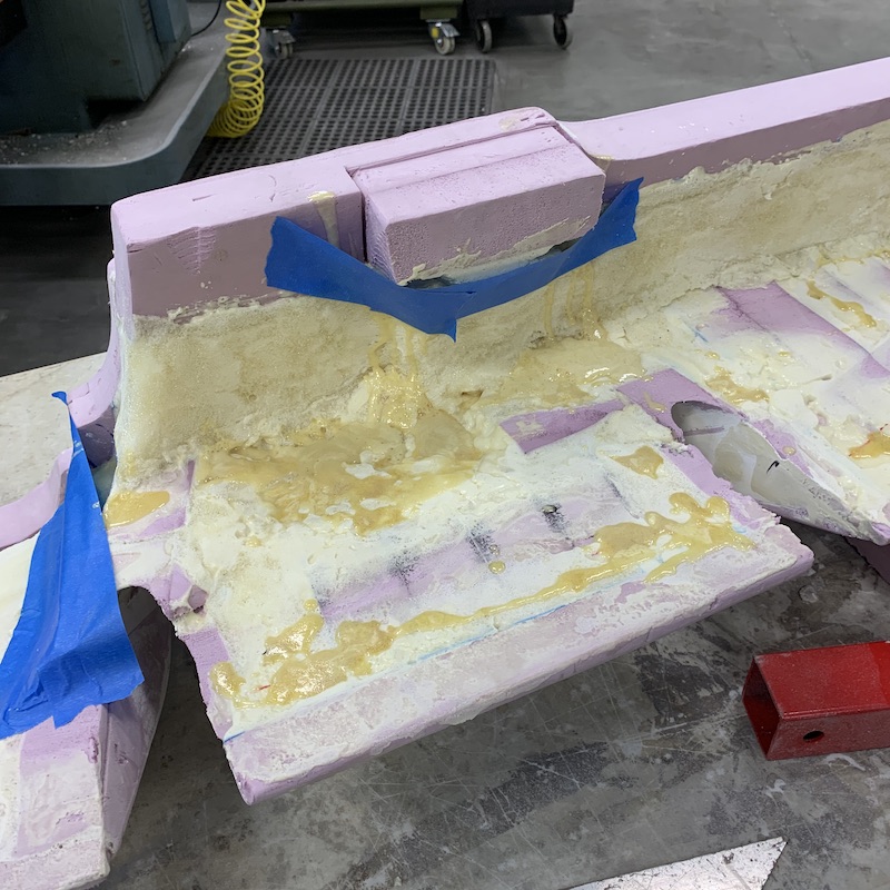
Wait for it to foam up and start to get warm and slightly stiff and spread it around then put waxed paper down on it.

It took it about twice as long to dry - no ability to off gas - but I'm pretty happy with the results. The stuff's spread pretty evenly and since this will never be seen I'm not worried about it.
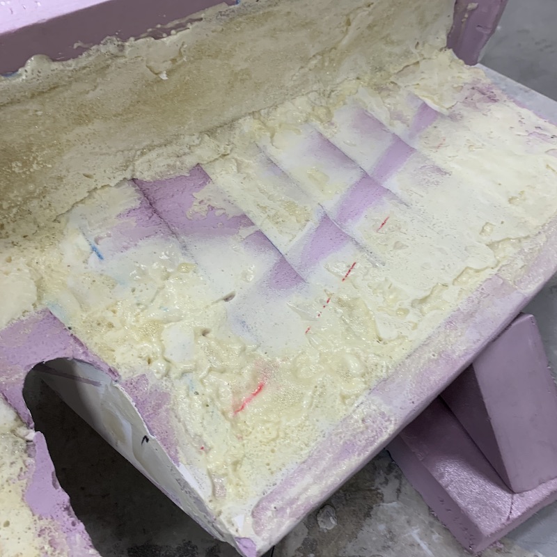
All mudded up. Will sand tomorrow and see if it gets more mud and sanding or if I get lucky and get to go straight to Bondo and sanding.
I hate sanding...
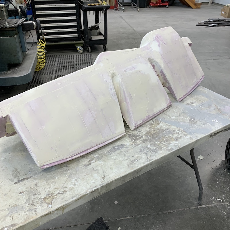
Gonna start on the headlight pods next. I'll start working on them as I wait for layers of what ever I'm waiting on to dry.
Aug 21, 2020
Headlights finished and reinstalled.
People ask why this project has taken so long.
Here, this is what's in one headlight and there are an electrical distribution plug, a wire shield and a few more fasteners missing from the picture:
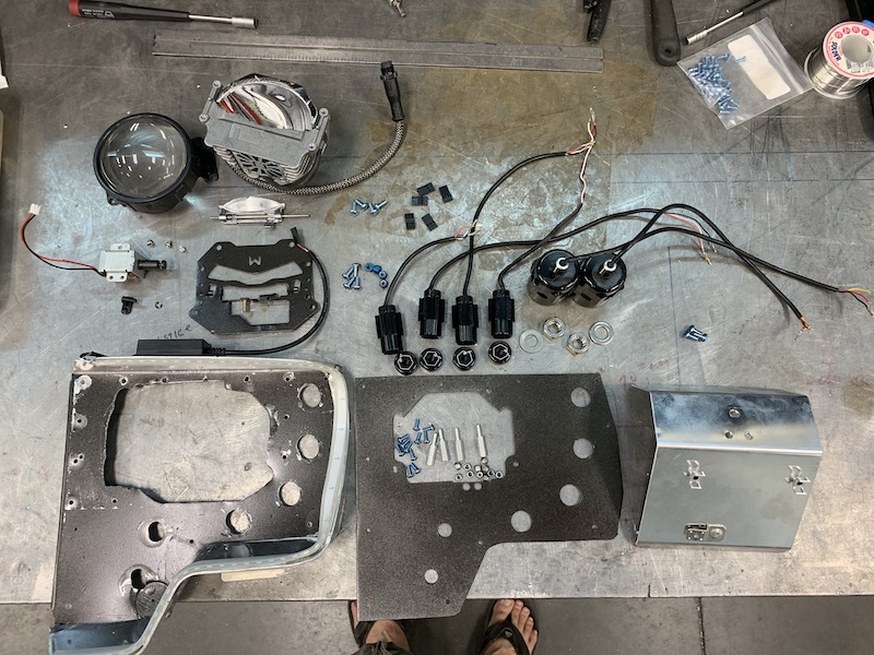
Ready to install:
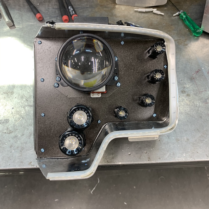
Back side with the new wire shield installed.

New main beam position - upwards and inwards:
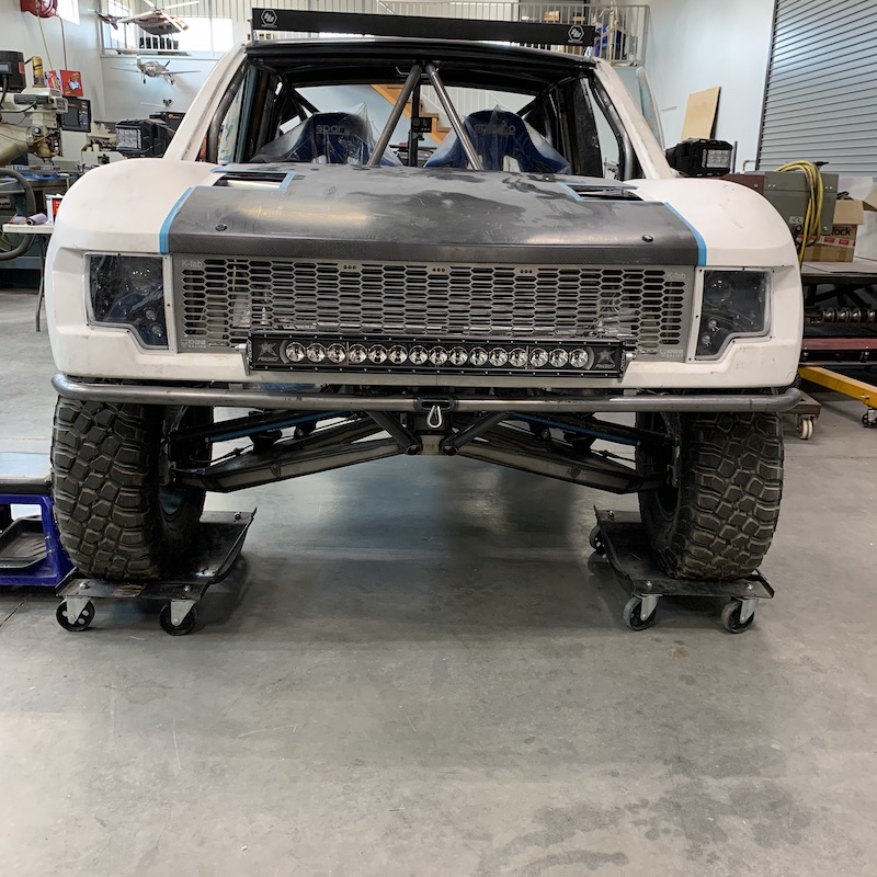
Accent/driving lights:
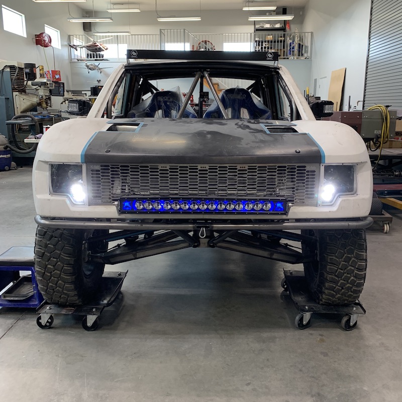
Running lights on:
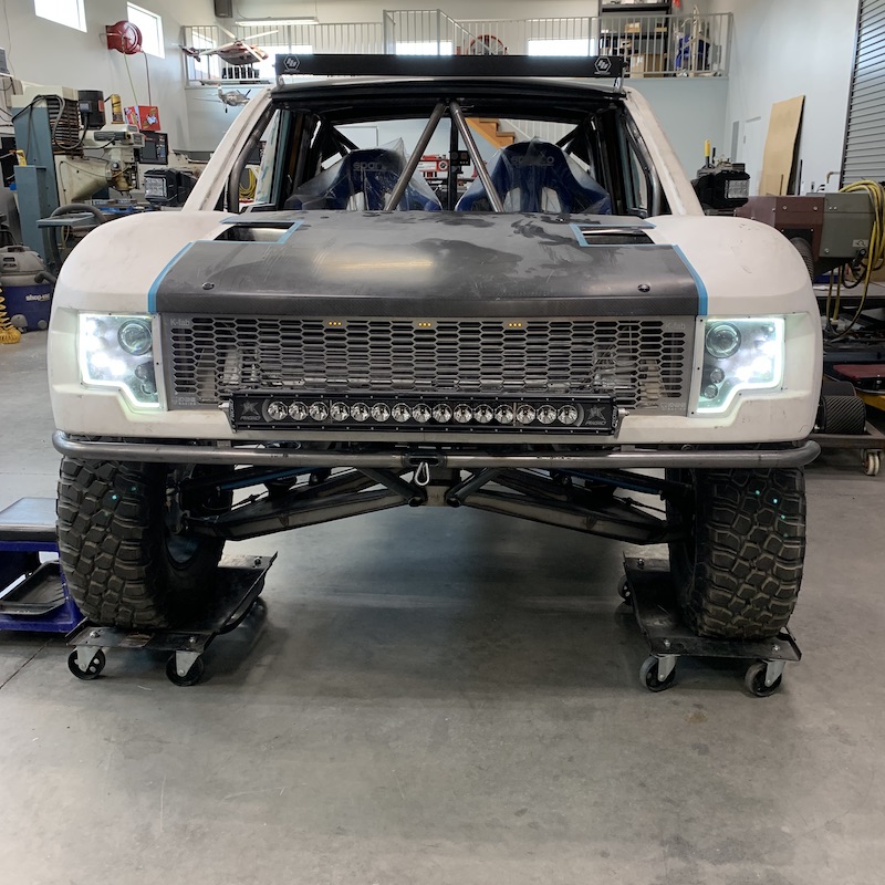
Left turn signal in action:
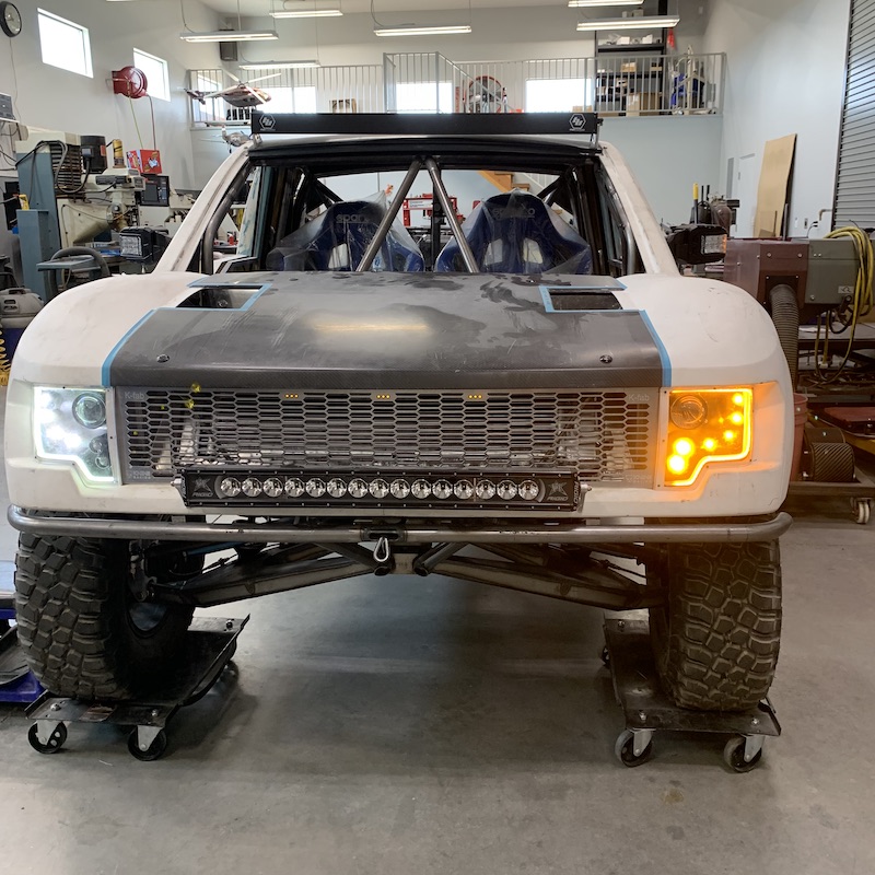
HOLY CRAP THIS IS BRIGHT!
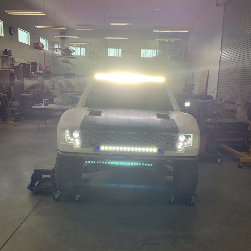
Got another coat of Bondo down and then another filler layer of drywall mud. More sanding and filling to come...
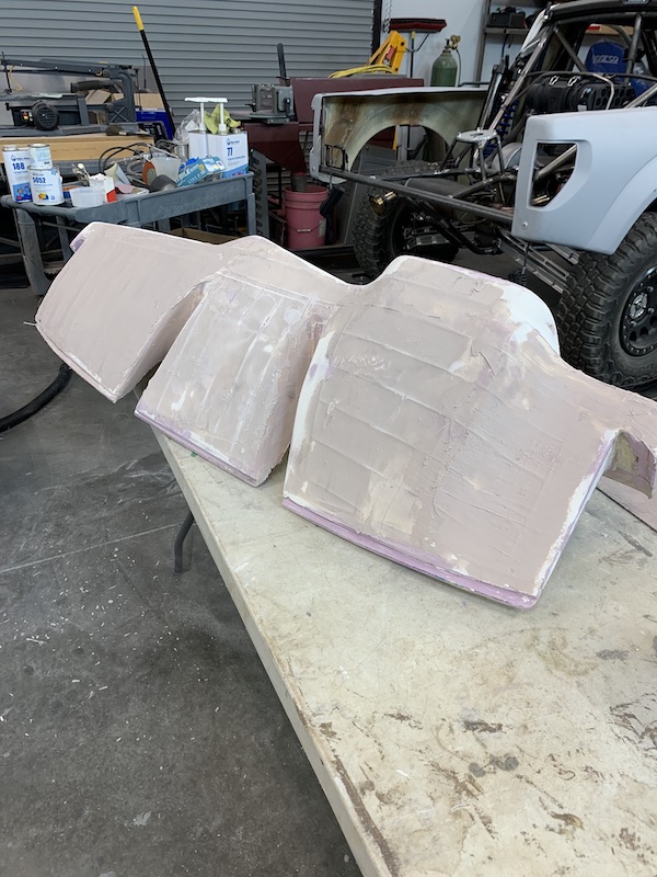
Sep 2, 2020
Just in case anyone noticed in the pic in the post above with all the lights on, the passenger mirror lights are not on - all good, just unplugged. I'd probably not noticed unless I'd seen the pic. Kinda surprised Bull didn't catch that one.
Anyhow, I'm SICK of sanding! More Bondo, sanding, drywall mud, sanding, rinse, repeat. Final coat of drywall mud before I throw a layer of fiberglass over it. It still needs to be sanded... (mumble, mumble...)

So while the stuff on the dash dries I've decided to go ahead and tackle getting the tail light pods wrapped and ready for bagging.
I have a roll of Kevlar (not really sure where it came from - it's been floating around for YEARS) that I figured I'd use in these pods. They're in direct line of fire from the rear wheels and I'll bet the roost isn't gonna be nice to them, so why not use it for the intended purpose?
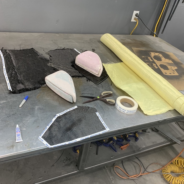
Well... It'd be nice to use if I could cut it!
I thought I had scissors that would shear the stuff - I've used it before, I've cut it, heck the roll's missing a piece. But I can't cut it! It mocks my special coated carbon fiber cutting scissors (both sets - and they go thru carbon so sweetly and easily), it just pushes into the cutting pad with the Olfa roller razor knife and a regular #11 Exacto knife may as well be a piece of coat hanger. Kevlar cutting scissors are supposed to arrive this afternoon. Good ol' Amazon to the rescue.
So I went about getting a couple layers of carbon in place and getting the light figured out with material around it.
First layer/piece is just the shell - mainly the cosmetic layer. I didn't take it all the way around and into the slot the light strip fits into. The edge get tucked up out of sight so all should work well.
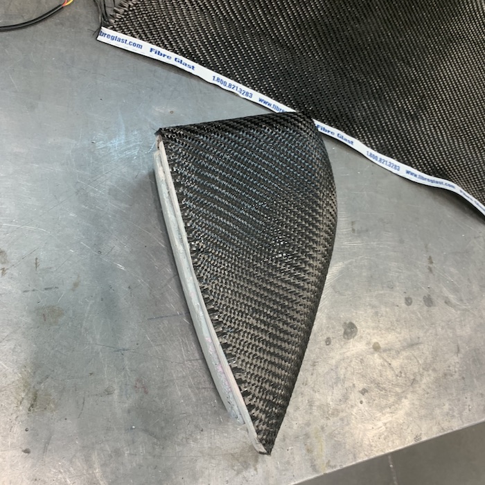
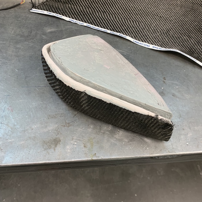
Second layer goes ahead and wraps around the edges and into the groove. Testing the fit and getting the carbon down into the gap:
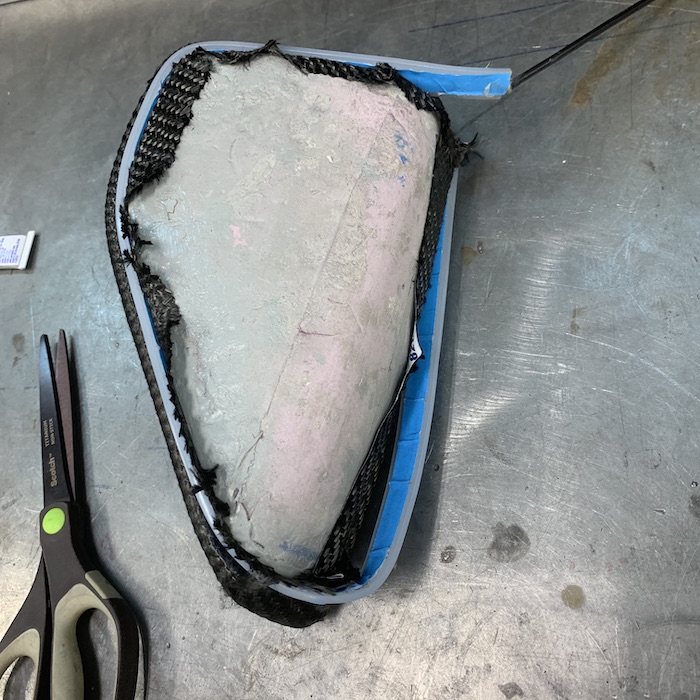
Lit up, checking how it looks - not too terrible. Only issue is that my $19.95 Amazon special light strip has decided to not flash the amber blinker the last six inches. I've wondered how sturdy they'd be. New ones (they're cheap and I'll figure out something to use the spare for) should be here today with the scissors.
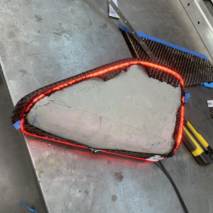
Since the last six inches was done I pulled the strip out of the silicone "wrapper" and stuffed the innards back in the slot. I wondered what it would look like without the diffusion the silicone thingy had. Guess who forgot that raw carbon fiber is a wonderful conductor? THIS GUY!!!
I had the pod in my left hand, right hand fiddling with the power lines and as soon as I made contact with the battery (using a LiPo from RC stuff - small, 14V, can pump out 60A easily) my left hand got very HOT! DOH! You idiot.
As soon as I get my scissors I'll throw two layers of Kevlar over the pod and get it ready for bagging. Once it's underway I'll work on the other pod - two layers of carbon, two of Kevlar. Should be sufficient.65chedderbob
Kevlar can be a real tough but to crack, or cut as it may be. If you're getting new fancy scissors for the job, I would strongly advise against ever using them for cutting anything but Kevlar. I worked with the stuff a bit this summer, and we had a pair of scissors just for Kevlar. Someone used them to cut one piece of carbon, which it did just fine, but when we went to cut Kevlar again, suddenly they wouldn't cut it anymore. Still cut carbon just fine, but wouldn't touch the Kevlar. Finicky stuff
Sep 5, 2020
Me
Agreed on the scissors only being used for one application. The Kevlar set won't get used on anything but.
Sharp suckers and they're serrated to hold the fibers in place for shearing.

Takes ratty cuts and makes them much better.
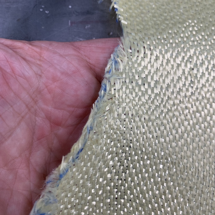
I took the suggestion of one of the guys on the Facebook page and got a roll of really thin continuous strand fiberglass veil. A little Super 77 and it glues right to the carbon and the Kevlar. Makes the cut edges stay nice and uniform. I learn something new every time I do this stuff.
Since I can now cut Kevlar, I added a single strip in the rear wheel firing line and then one full body wrap.
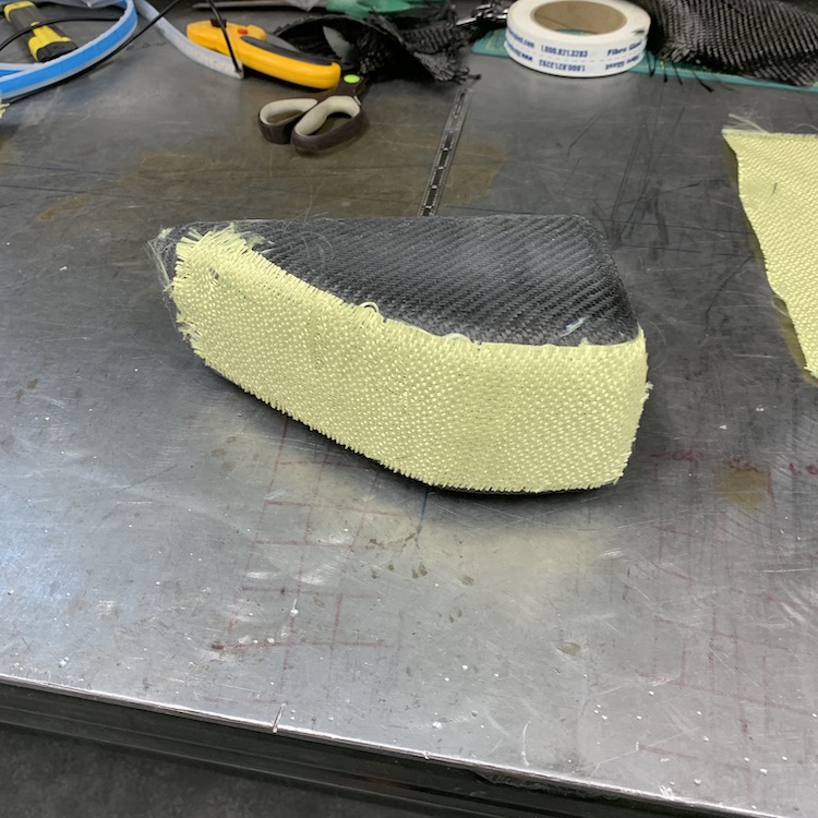
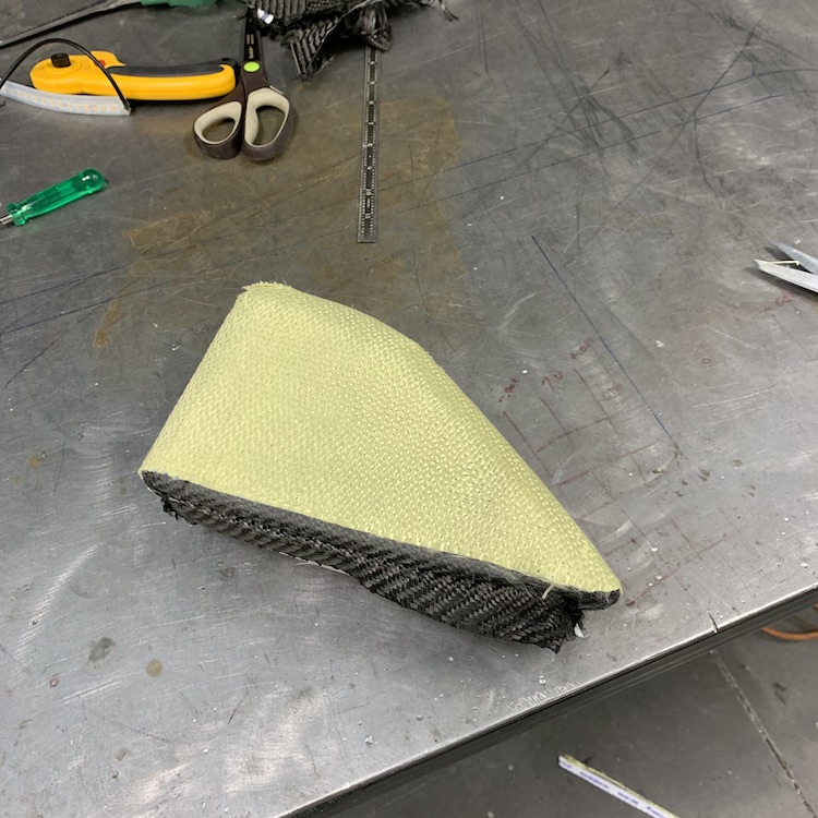
Then one more layer of carbon, stuff the LED signal strip into the gap and get it all set for bagging.

Testing the bagging. I learned from the center console that you gotta make sure there are no leaks anywhere BEFORE you start infusion. This piece is small - easy to find the issues.
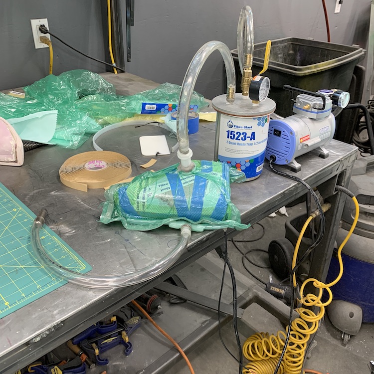
Once I got it sealed up I let the epoxy flow - you can see it in the feeder tube.
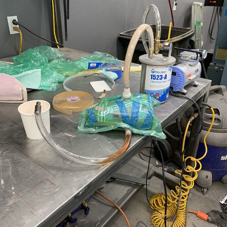
Set time on the epoxy is supposed to be 70 minutes. I've a call into Fibreglast about my set time being a lot longer - like four hours before gelling. They wanted lot numbers, they got them. We'll see what they say. This epoxy will fully cure after about 4-6 days w/o any time in the oven but it's supposed to set in 70 min - and yeah, I got the ratios correct. Was the first question customer service asked...
Had the Wizard suggest UV to kick it a bit quicker - only UV I have is outside (which may not be a bad idea now that it's hardened - maybe some of the crap I gotta pull out will be affected.
So pulled the bagging off and ended up with an 8 out of 10 piece. Some of the straight edges pulled a bit, I'd not prepped the mold correctly before laying the carbon on (gonna be a bit of work digging out the stuff next to the carbon). It's all gonna get hidden by the tail light and the lens so all is good. The cheapo LED strip also decided to drop about 6" of amber in the flash - thinking I can pull this out and wrestle one in - have two left so ...
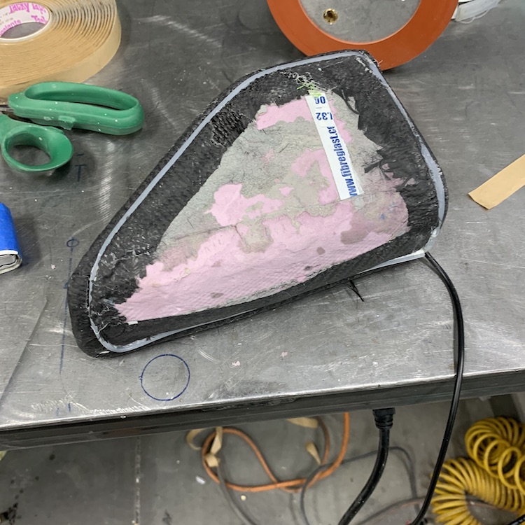
I'm going to leave the outside just like it is - raw. Can't see why I want to cover it in polyester just to have that get all beat to shit by roost from the rear wheels.

It fits well, though.
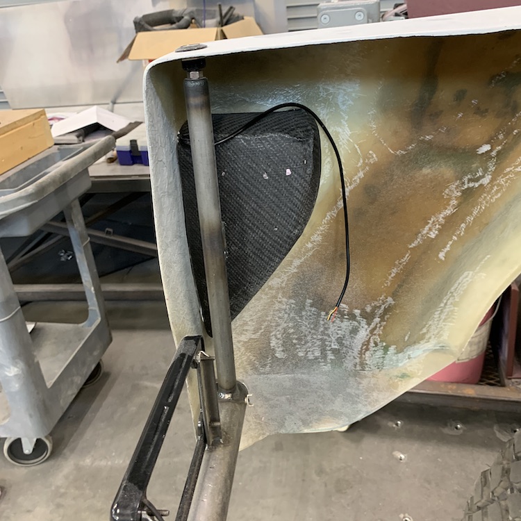
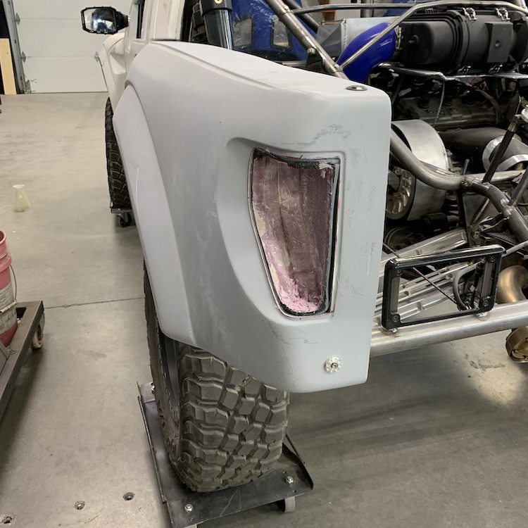
Gotta clean all the crap out - this should be interesting. Get to play paleontologist and find the carbon under the layers of stuff.

Sep 8, 2020
Driver's side tail pod is done - or at least as far as I'm taking it... After getting out what I'm removing of the mold from the pod: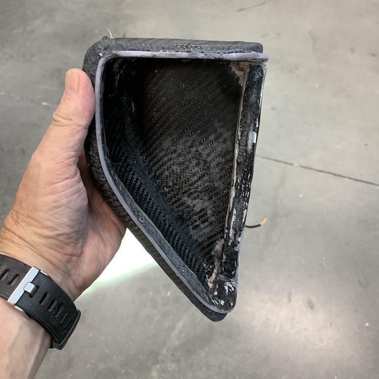
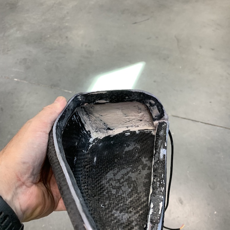
The pod pretty much clips into place. Not happy with the vertical strip/side fitment and the cheapo LED strip decided it was gonna blink out on the amber strip so my turn signal looks a bit compromised. Ended up being a non-issue, though. The Rigid tail light ends up needing a tad more room to fit and the vertical strip and the area that housed it got removed.
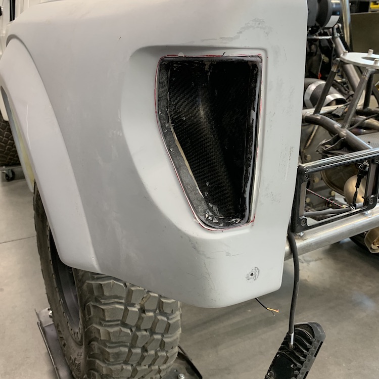
Everything in place. Rigid light fits nicely against the edge of the opening, the defective strip won't be missed and it's gonna make the other side easier to mold.
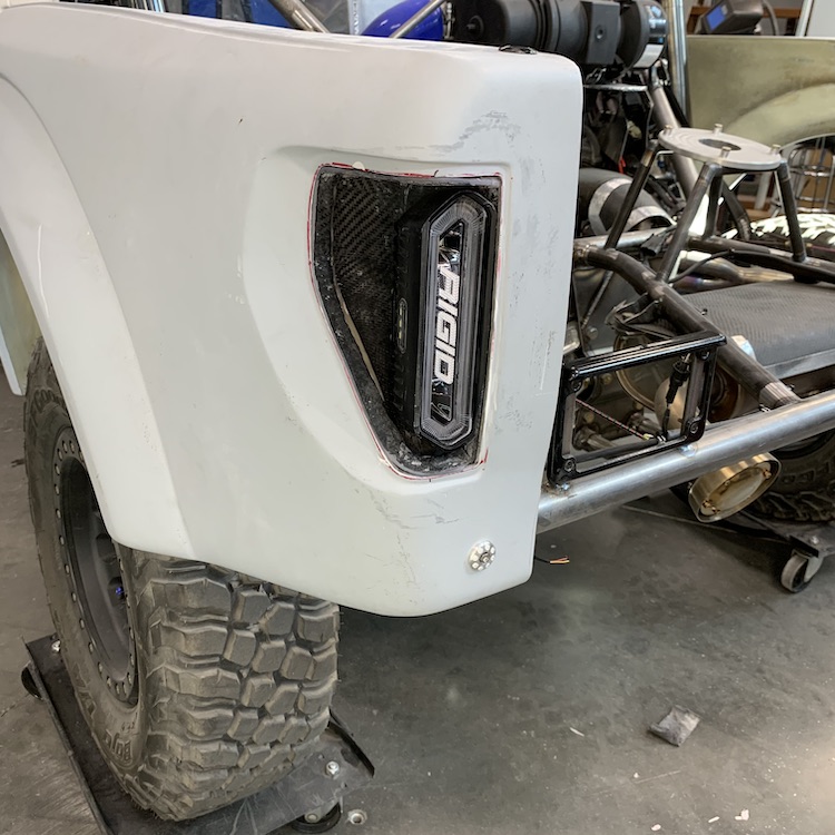
Like I said elsewhere I'll give this an 8 out of 10. Not overly pleased with the results but I'll be able to hid the crappy aspects with the lens that goes over the opening and a little creative black paint framing on the lens to cover up gaps and stuff.
Hopefully I'll get the second pod under vacuum and infused before the day's over.
Sep 13, 2020
Passenger side rear tail light pod done and installed. I still have to wire both pods (put connectors on the ends where I cut the wires).
Once again, two layers of carbon, a strip of Kevlar in the main rock catching area, another full layer of Kevlar and then two more layers of carbon:
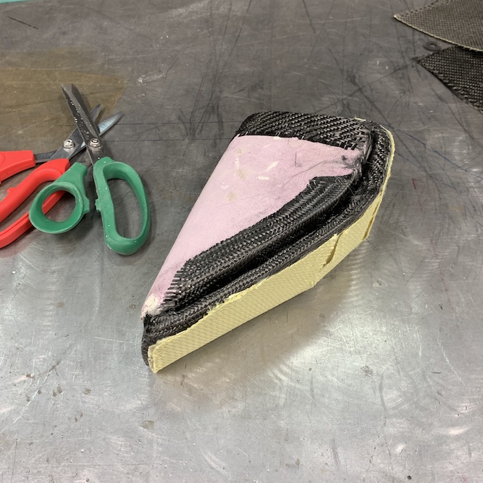
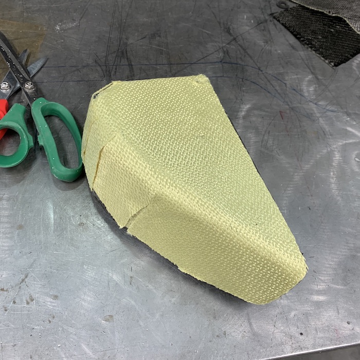
Working the LED signal/running strip into the mold:

Infusion underway:
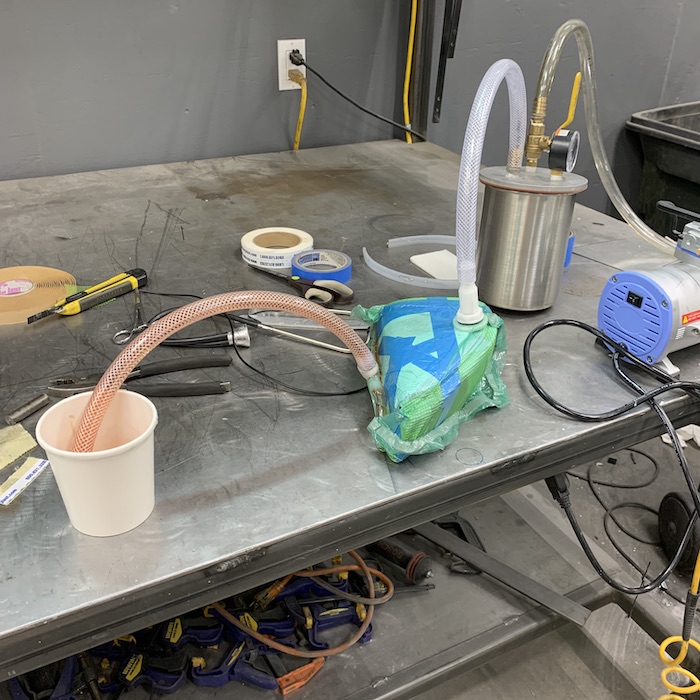
This one cleaned out a lot better. The surface of the mold was smoother, the Bondo was thicker, so it broke out with a chisel much more easily (almost no sanding).
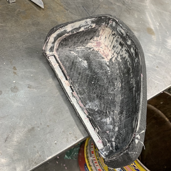
Installed and waiting on wiring to be completed.
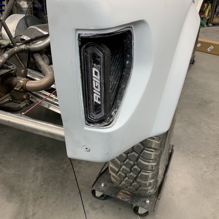
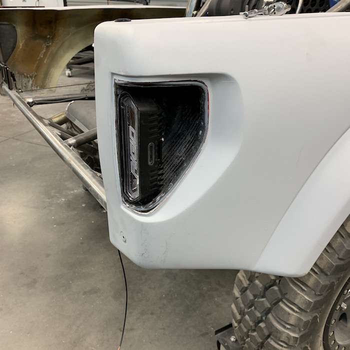
The cheapo Chinese LED signal/marker strip decided not to be a red marker light anymore. Didn't matter which wire was powered, the strip just went into amber blinker mode. Fortunately I had already purchased a backup set (since the first pod produced a sacrificial lamb strip) so it turns out that both the original strips were there for support, making the part and then finding the round file. The two new cheapo Chinese LED strips are in place and seem like they're gonna work.
----------------
I think I've figured out how I'll make the headlight and tail light lenses. Gonna knock out sheet aluminum pieces that fit where the lenses go. I'll then cut a piece of Lexan that's just a tad bigger than the aluminum form, come up to the house and invade the kitchen. Throw the aluminum with the Lexan on it into the oven and turn it up. The Lexan should hit melting point and lay down over the aluminum mold, copying it's shape perfectly. We'll see if this theory works or not here soon.
----------------
Dash... I've been avoiding it, in case anyone didn't notice but I guess it's next in line. I'm just SICK OF SANDING!!!
Was asked by flyerrrider about the A/C - it's probably going to be the final (main) aspect of this project. I have to get the dash done so I can get venting routed and installed in the dash.
Still need to get the door windows figured out too, along with carbon inner door covers made. Have the materials now.
I also have to redo the heat shields around the exhaust. The pieces around the header, even with the high temp shielding stuff lining them, like to sit there and smoke after a run (must be awfully satisfying for them?) because I didn't use high temp epoxy.
I'll use the existing pieces as my molds for the new pieces with the high temp epoxy. Gotta cook them in an oven for a bunch of hours at different temps to get the cure correct. Will also replace the piece I have over the muffler with a high temp resin part.
----------------
Have had a bit of PBO (Project Burn Out - have I said how much I like sanding?) and with the record setting temps (hottest July and August on record - both months averaged just under 100F/37.7C, we had 54 days above 110F/43.3C - almost double the previous record and I think it was 17 days above 115F/46.1C) we suffered through this summer (couldn't keep shop comfy) I had to step away a bit.
Weather's back on track and tolerable now. The dirt and the desert are starting to call me and the Katoom 350 back out - "Come ride in me!" Actually, I went out with a guy a week ago (newbie to the dirt but road races) and he managed to fracture his foot/ankle (cracked things). Seems every time I take someone out I kill them... Probably best I remain a SOSR (Stupid Old Solo Rider - pronounced Saucer).
I should be able to get the Mini-Raptor out into the dirt and start playing with engine and suspension tuning soon.
Originally I wanted to get this project finished before the end of 2020 but I don't think so anymore...
There's a many years long joke between a friend of mine and I about the time line - he's called it 2020 since before I left Hell (Ohio) six years ago. The way this year's gotten along, I don't think I want the Mini-Raptor to be done before year's end. There's gotta be some sort of curse that will be put upon it if I do.
Sep 19, 2020
bdkw1
I'll take that bet. Say sometime in dec? I have a bike that is a year and a half old and has less than 200 miles on it, something must be done about this.
Me
I've a new helmet light that's getting tested tonight. Been a stressful, funky week and I need to go scare myself a tad and get rid of the ooogeebooogeees.
Come on down - we'll go run around in the dirt.
-------------
It has been a quality last couple of days in the shop though (well... except for one part for flyerrider that I made wrong twice and then the Proto-Trak went poof-ka-boom again. Fortunately the control's still within the 90 day warranty since I replaced it something like 88 days ago).
First off I have the brand new K-Fab semi-autoclave in house. I can make tea and mold shit at the same time now. Stickers to be applied - can't have a shop oven with no stickers...
$75 off of Craigslist and now I won't get kicked outta the house for curing composites in the house. Probably the best $75 I've spent in a while - if nothing else to keep me from getting in trouble! (my wife is very cool, btw)
I have a couple of lenses that Ben supplied but I don't have a full set so it was time to figure out how to do this again. I tried the vacuum thing, what, three years ago?
Decided I'd make an aluminum piece that represents the lens, throw it and some Lexan in the oven and see what happens.
Driver's side mold and the sanded lens that Ben supplied:
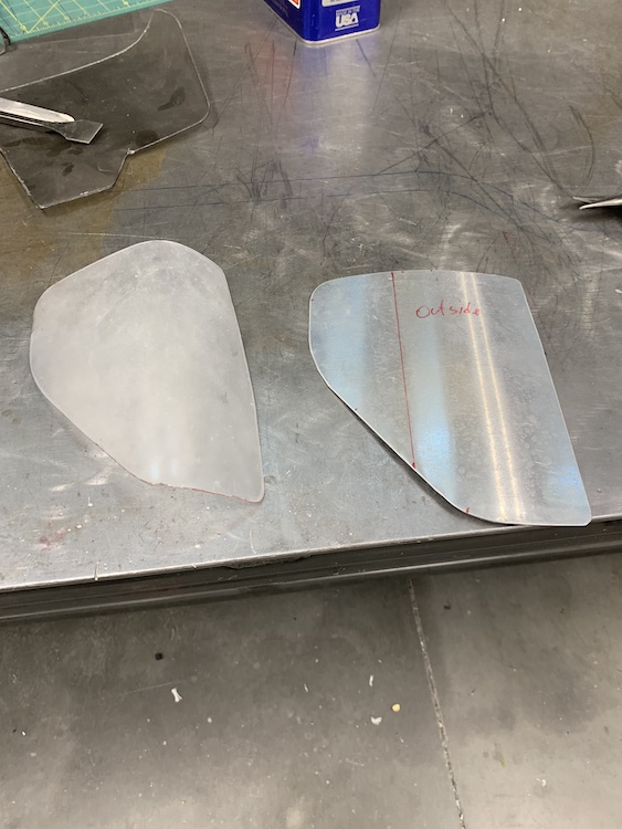
Mold and lexan ready to go play in the oven:

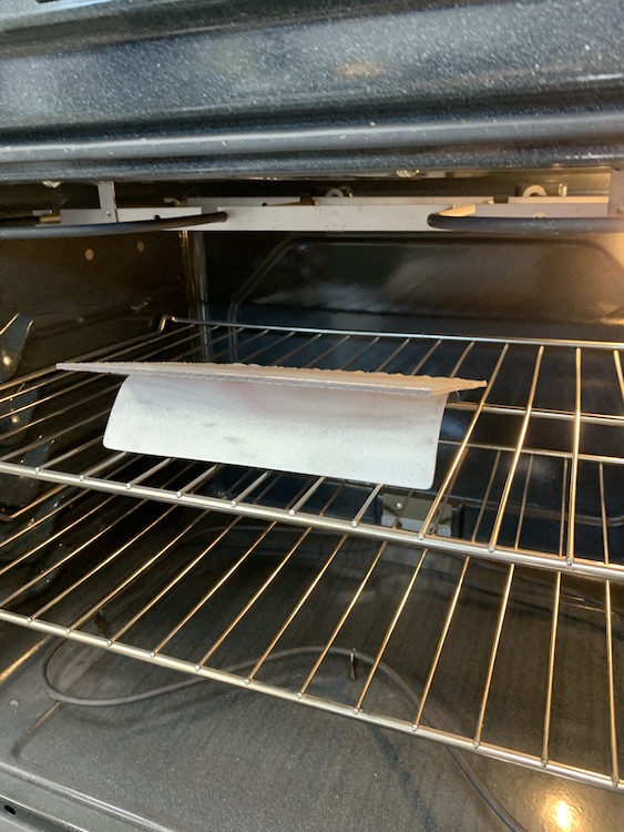
Ragged edges and I touched it with dirty welding gloves. Fortunately that's the cover sheet stuff that's all messy. I realized after the initial drooping that I needed to trim the edges closer to the mold. Did that on the second one and it made a huge difference.
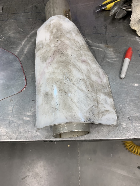
Cover sheet removed:
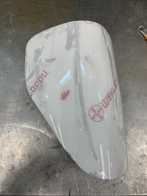
There was a little lifting (actually it didn't droop enough) so I threw it back in the oven for a few and then just squeezed it together - worked perfectly.
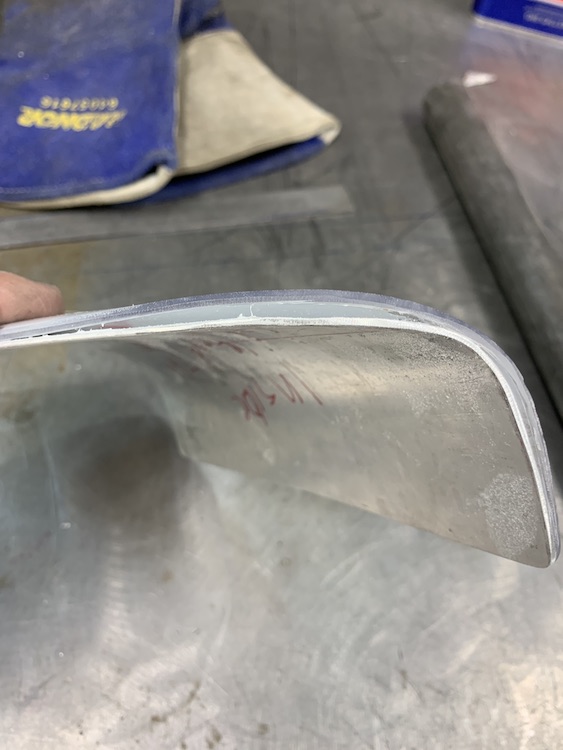
Here it is pulled off the mold. Worked really well and now I have molds to pull more if I should need them.
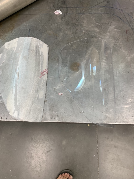
Made a plug for the passenger's side (really came out quickly - like wow, that was fast, quickly) and also cut the piece I was going to mold much closer to shape. Pleased with the results.

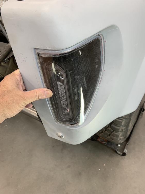
Sep 22, 2020
First thing to tackle with the high temp epoxy was the muffler shield. My first attempt (using regular epoxy) came out really nicely but it popped right off of the aluminum body and it, like the rest of the stuff around the exhaust, liked to smoke after a session (must have been satisifed).
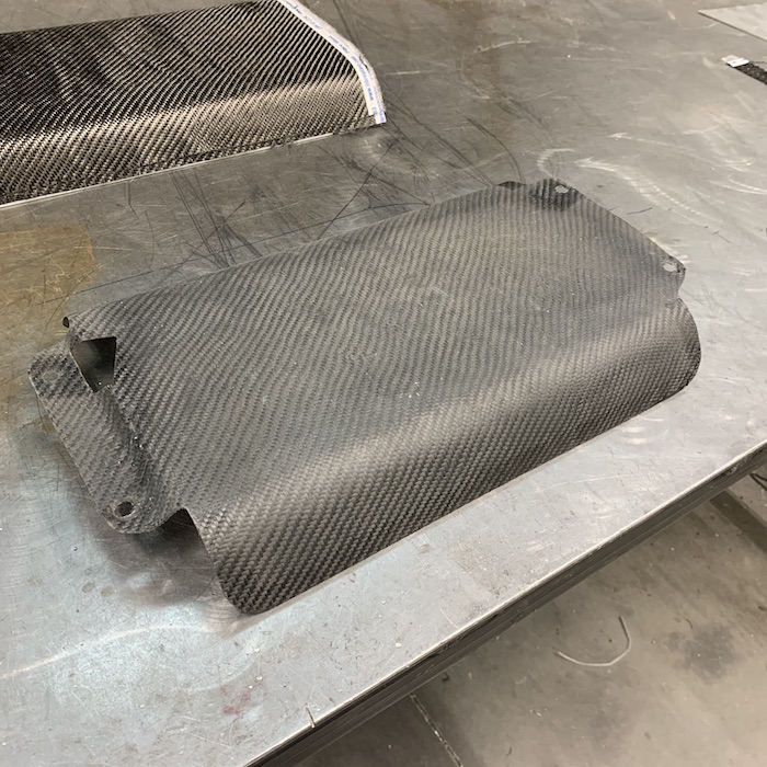
It's a nice piece... Light, stiff, good cosmetics. Bummer it's not correct.
So back to Fibreglast.com to get the correct epoxy. - High Temp (kinda wonder what "high" is? - no, not that kinda high, temp high...)
Two layers of carbon with the fiberglass veil (man that makes trimming NICE!!! - no mo fuzzies whoop whoop!) applied:
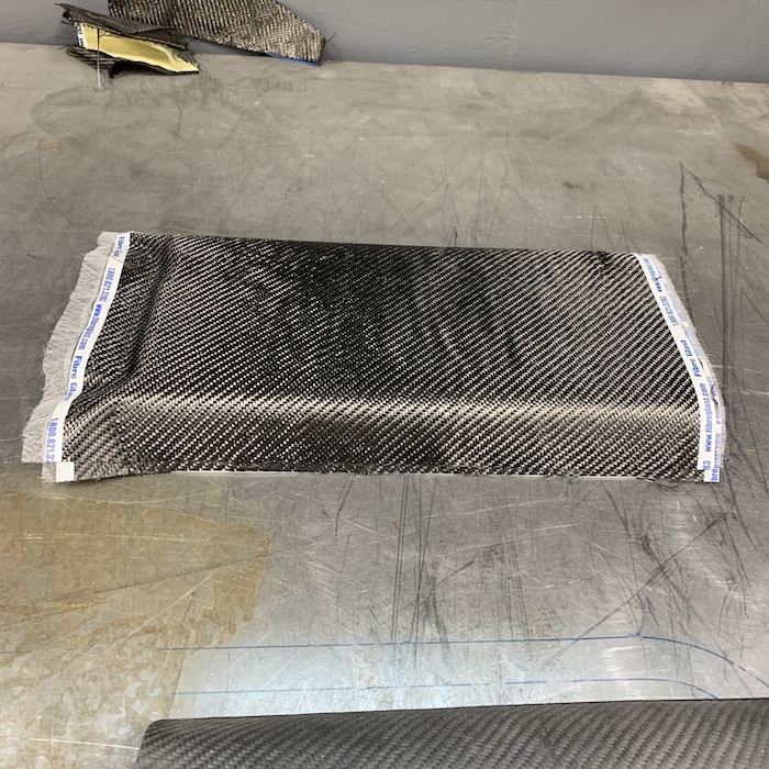
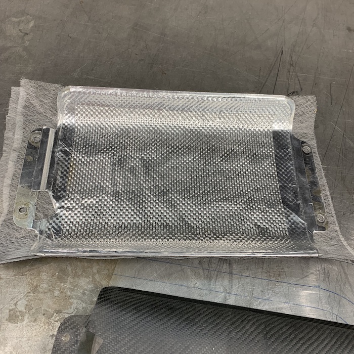
Edges trimmed, ready for the edging strip (see how nice and clean the edges are?)
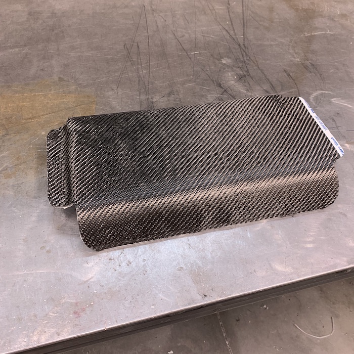
On the first try, I had the high temp tape that seals the edges of the aluminized fiberglass heat shield over the carbon. I did the carbon layer then put the insulation in and then taped it in. The tape didn't like the carbon and kept wanting to peel up.
So this time I put the sealing tape on first, attaching it to the aluminum pan, which it likes to stick to. Then I ran a carbon strip around the edge of the shield, effectively trapping the tape so it can't go anywhere.
Here's the inside showing the overlap that will seal the tape:

Top side view:
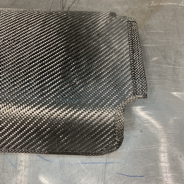
Sealed up on the first try! Yay! Like I said earlier, I'm getting better each time I do this stuff.
Ready for infusion:

Infused and waiting on it to set (3:35 p.m.): (really big difference from the pic above, eh? lol)
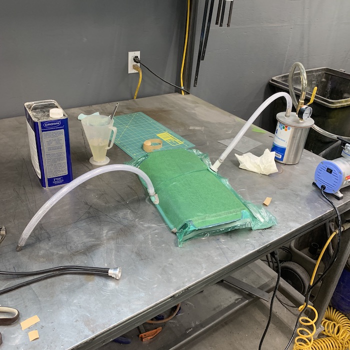
Went down at 5:00 and it was still liquid. Went down at 7:00 and it had started to set. Closed up shop and told it to sleep well. Left it on vacuum for the night. Instructions say set time is 18 to 24 hours, gel time is supposed to be 90 min but is (like the other infusion epoxy I've used) more like 3 hours.
Went down to the shop this morning and am very pleased with the results. Two minor blemishes - both involved in the infusion process. I have a small spot under the vacuum port (I put it on a radius instead of a flat - note to self, only put on flat) and there's a little puckering along the other edge where the feeder tube was. Like I mentioned somewhere else, it's an off road truck, not an F1 car so a few blemishes (a lot? - don't look the MR over too closely...) are acceptable.

I was REALLY pleased with the way the edging came out. It sealed the tape down nicely.

Today it gets cured.
Stuck it into the K-Fab semi-autoclave and set the temp to 170F/76C (supposed to be 150F/65.5C but the oven's lowest temp is 170). It'll spend 3-4 hours there at that temp then another 3-4 @ 250F/121C with a final 4-6 hours at 375F/190C. Then I have to bring the temp down slowly, which will be interesting and probably really boring.
Gonna see what I can do about getting the three other pieces (upper and lower header shields and one in a corner bend) prepped and ready for the same fate as the muffler shield today. I'll have to do each piece on it's own so that's three more days of this stuff.
Anyone notice how much I'm avoiding the dash? It needs sanding....
Sep 23, 2020
Interesting observation I just found on the cured carbon cap I made for the muffler. The epoxy did not adhere to the aluminum panel. The carbon cover turned out well, is fully encompassing the piece like I wanted but there's no adhesion. I'm gonna run it anyhow. Will be interesting to see what happens to it and also to the piece below - which went into the oven at 6:30 this morning.
--------------
So just like the muffler, the carbon cap on the cover that shields the ends of the headers from the world and spare tire popped right off. The tape held better on this than the muffler but it was still starting to go.
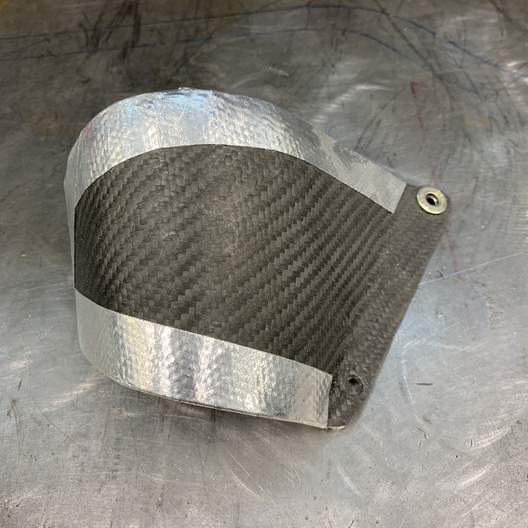
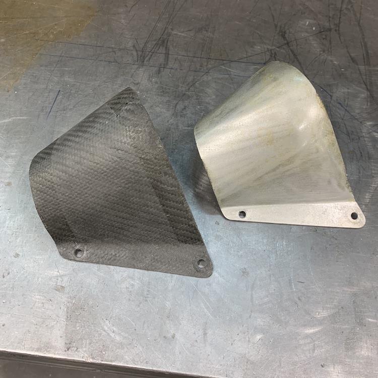
The middle header's turn down was also hitting the cover so I had to do a bit of modding with a hammer and a lot of grunting. There's now about 1/4" of clearance between the heat shield and the bottom of the aluminum cover.
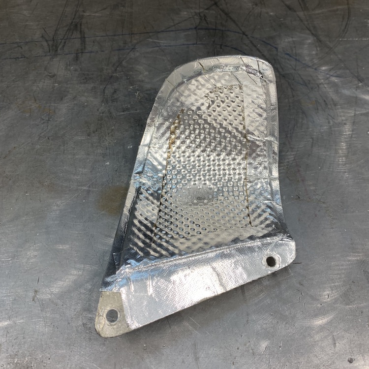

Since the tape sticks so nicely to the aluminum, I made sure I got it down nice and tightly when I put the new shielding in:
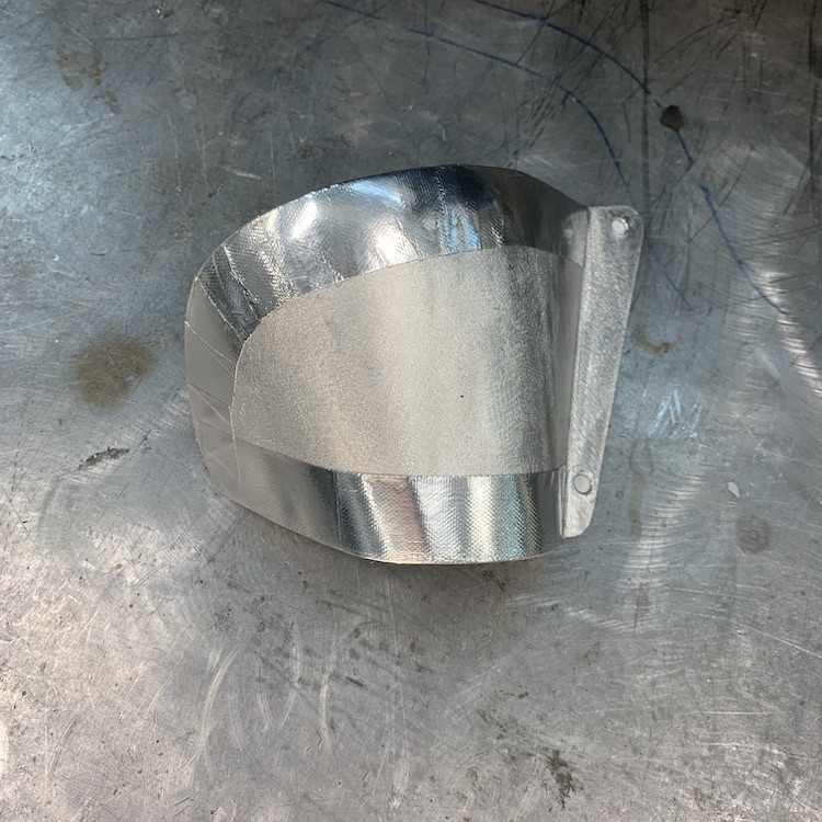
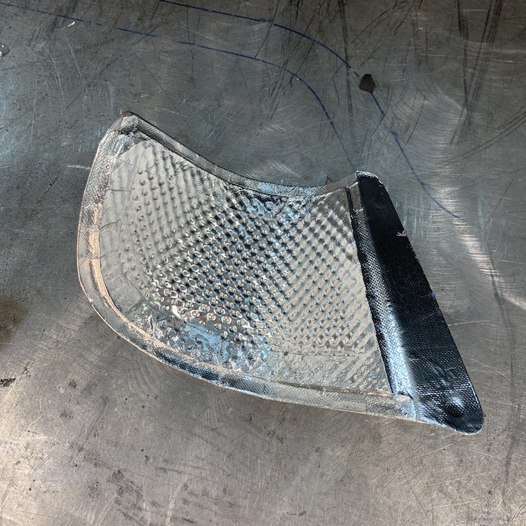
Like I did on the muffler, I capped the edges with a 1" strip of carbon.
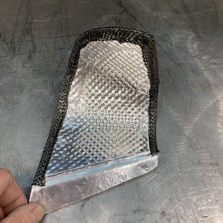
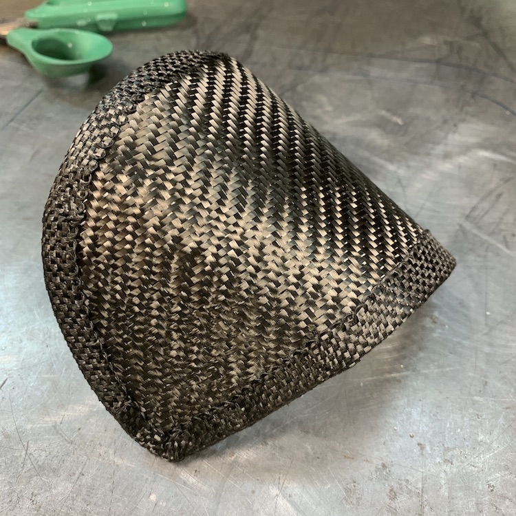
Underway last night. Like the muffler, it set up after about 4 hours and I just let it sit under vacuum until this morning. When I unwrapped it, I had a blemish, like on the muffler, where the vacuum line is but otherwise it looks like it came out well. It's cooking for the day.
The two pieces that wrap the headers (pic below from March 23 of last year - post 1799) don't have an aluminum aspect so I'm still trying to figure out how I'm going to make the high temp pieces and get the aluminized insulation integrated into it. Gonna make a phone call to Fibreglast.com and ask a few questions.
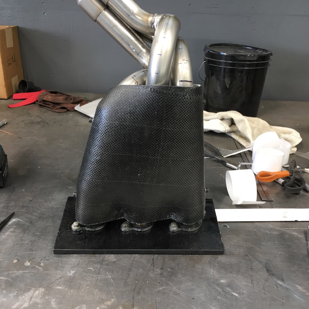
Sep 25, 2020
It's interesting that some of the high temp stuff I've looked at says you can cure upwards of 700 - basically to service temps. There's a long drawn out lowering of the heat and such for the cool off period.
Pleased with the results on the little cap piece (one blemish from the vac port). It doesn't seem to have separated from the aluminum (as much? - much smaller surface area and it's curved so maybe I just don't feel the delimitation?).
I like the bronze tint, too.
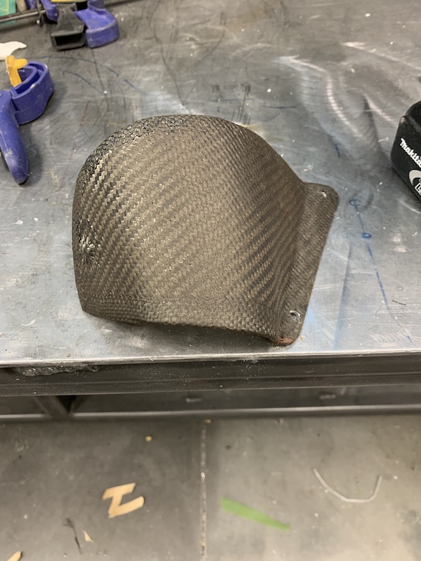
Have to laugh at the dust on the front piece. That's next.
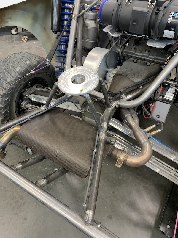
Oct 11, 2020
Header shields are done - now just have to trim a touch, clean them up and put the heat shield stuff in them.
Two layers of carbon Super 77'd to the foam layer:
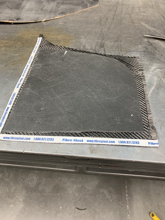
Main foam layer is 1/4" (6mm) thick and the other one above is 1/8" (3mm)
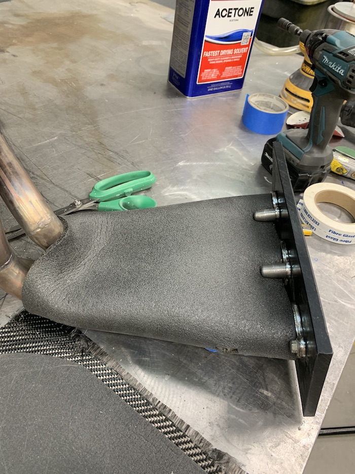
All wetted out and waiting to set.
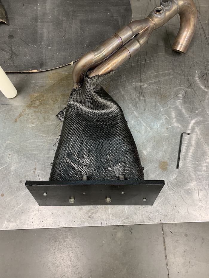
Came out nicely - lots of space around the headers.
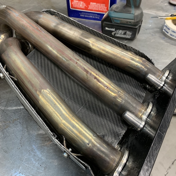
Comparison between the first non heat proof cover and the new one - lots more protection.
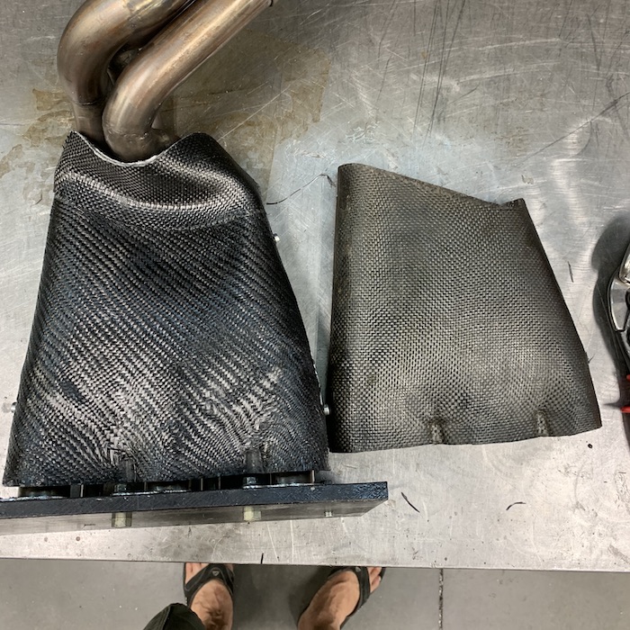
Don't know why this piece didn't brown like the other two - thinking maybe the others are wrapping aluminum so maybe it's picking up something from that? Dunno.
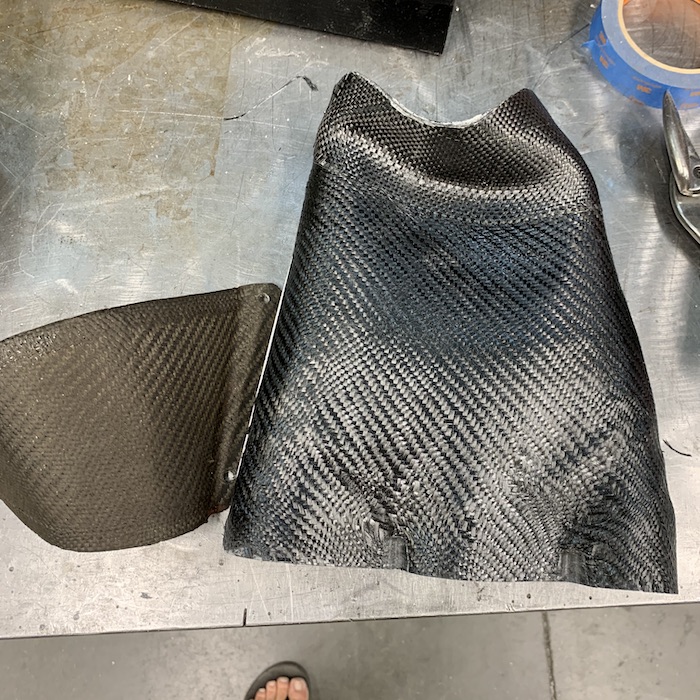
Starting the top shield. The thick layer first, wrapped across everything.
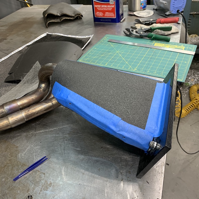
Integrated button holes and washers into the edging strips. These will hold the aluminum clamping pieces in place too.
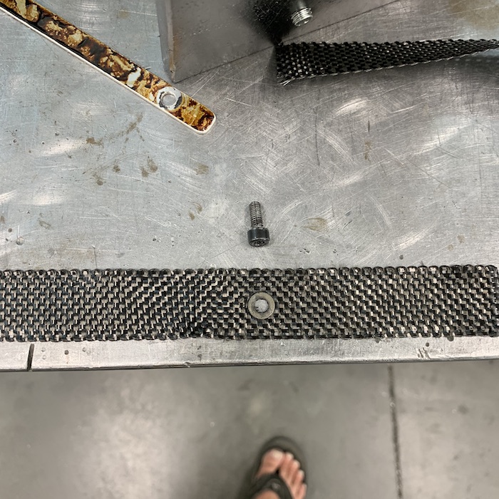
Here's the edging strip laid in place.
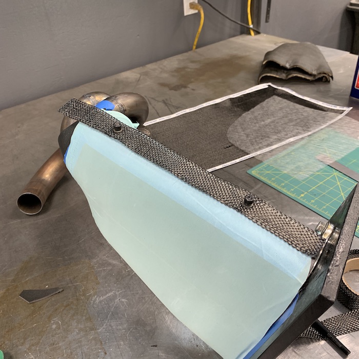
Getting the carbon cut and fitted. The thin fiberglass veil between the layers makes edging really easy. Once again, wish I'd known about this stuff years ago.
You can see the two aluminum clamping pieces here - they got hidden between the two layers and that capping strip.
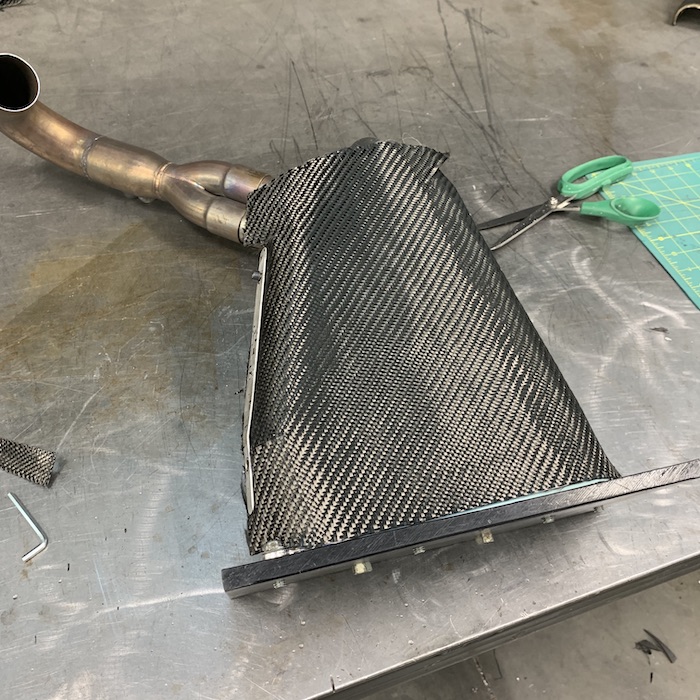
Wetted out.
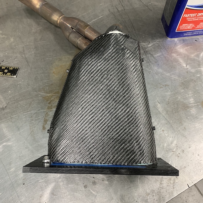
Edging worked like I hoped.

Close up of the mounting bolt and washer in the edging strip.
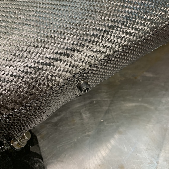
They clip together like the first set did. Yes!
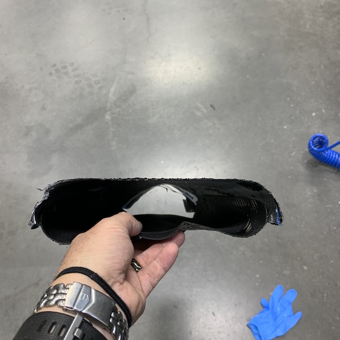
Top shot of the top piece.
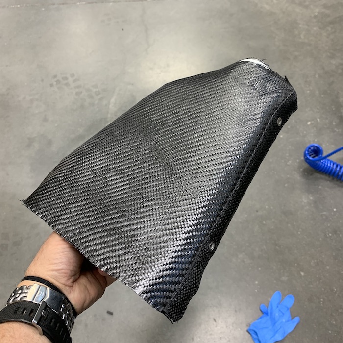
Lots of room in here.
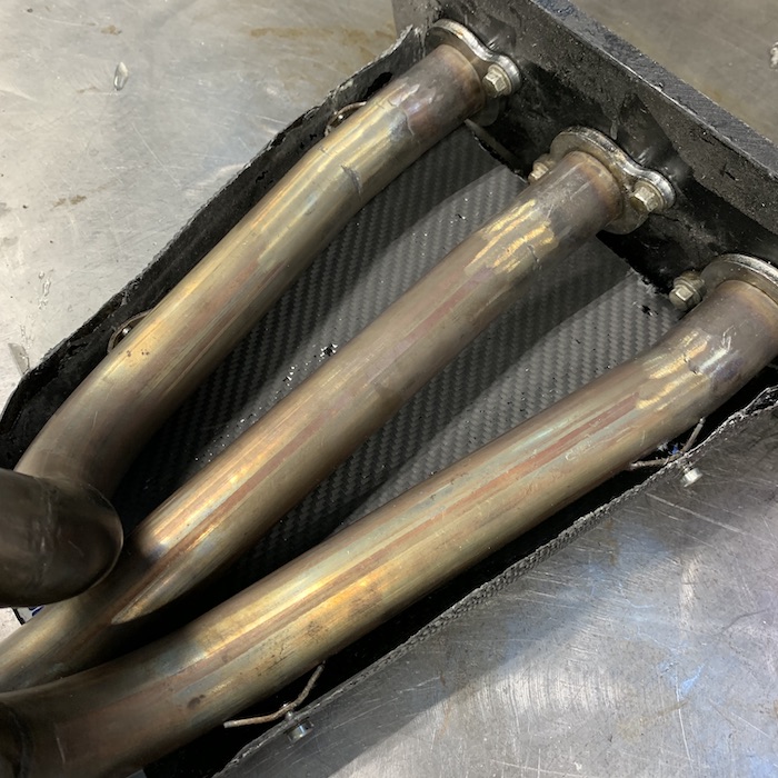
The top piece came out of the oven this morning. A bit of trim work, put the heat shielding on the insides of the shields and that's done.
Headers are headed out tomorrow to get ceramic coated.
Oct 17, 2020
Header shields are finished - got the heat shielding in place, things all trimmed and such. They're ready to bolt in once the headers get back from ceramic coating.
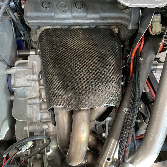
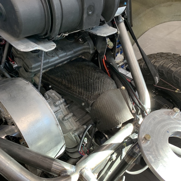
Next is some back end panelling. I don't like the fully open/exposed look so it's time to dress up the pig.
This area needs something covering it. At first I was thinking aluminum with a cover of carbon but after making the panels I realized that I've knocked out a couple of decent molds (they need some additional flanges for feeding the resin added - that comes a bit later).
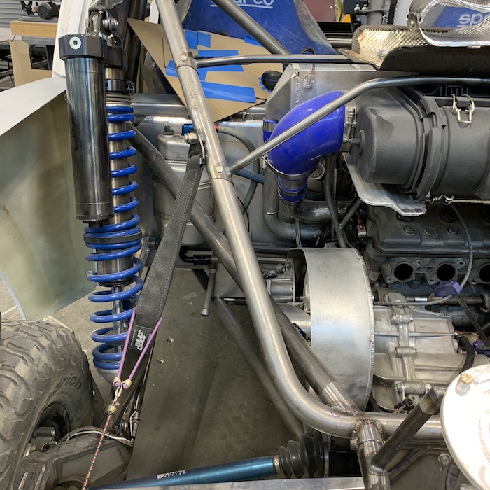
CAD work in action:
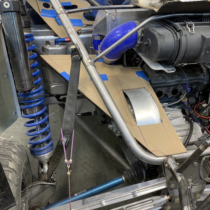
CAD to aluminum. The bump is so I have a clean full access to the belt.
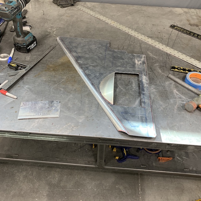
Installed - very pleased.
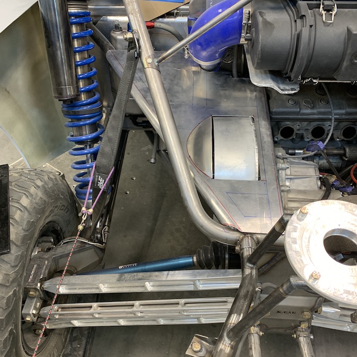
Once I got the big panel set up I started on the oil res cover (actually I started here and then quickly realized that I needed to do the main piece first). I had a mental visual, with a stepped lip where the two pieces fit together. It looked good in my mind's eye. Doesn't look so good in real life.
Where they come together looks cobbled and doesn't blend well at all. Didn't really see this until I snapped a pic and started studying it.
This wouldn't be a proper Mini-Raptor project if I didn't make at least one thing twice.
The res cover gets redone and will blend into the back panel at the bend instead of having that little lip with a really bad blend lip. You can only go so far in cardboard (it's flimsy) so I took the CAD piece, made an aluminum piece and now that's gonna be the pattern maker for the next mold. It's not that complicated and I know which bends to do first this time (never fails... ALWAYS one bend that gets in the way of everyone else).
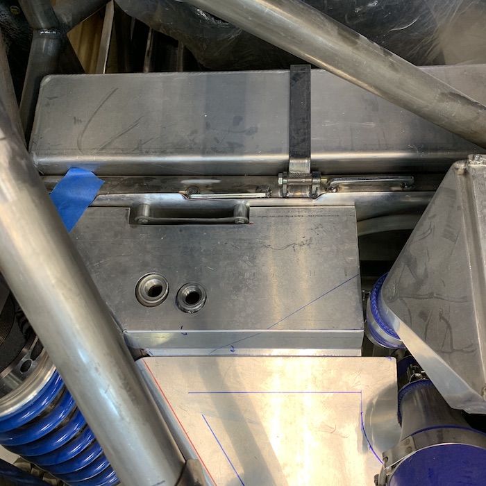
Even got the two molds primed and ready for a bit of sanding and then molding but alas, the small one will end up in the rubbish bin.
The three pieces you see in the large panel will become perforated inserts that fit into the carbon. They'll get pulled off the mold, stuck in the mill and filled with holes. They should drop right back into the carbon and fit like a glove. I did this with the lid on the glove box in the center console and it worked perfectly. I'm also going to be trying out some stiffening strips on the panel - will have ribs that run through it for stiffness. I'm starting to introduce new techniques and processes as I get this stuff figured out.

Hopefully I get a shop day today - not sure what Robyn has in store for us other than dinner with friends later the afternoon.
Oct 22, 2020
Two more pieces knocked out and I'm happy with them - of course they didn't play nicely (one worse than the other - more below).
First thing was to lay up carbon in the big mold. It all went in nicely and like a dumb-ass, I missed two major things...
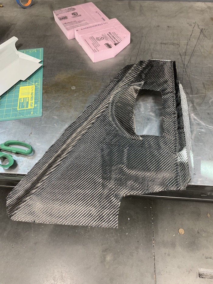
Testing the vacuum - yes! It has a full pull, no leaks and is ready for action:
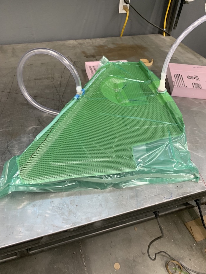
Resin introduced into the system - notice that you can see the carbon under the green mesh? Uh... not supposed to see that. There's supposed to be a layer of peel ply under the infusion mesh. I realized this when I went back to check on progress about two hours after mixing and infusing. Too late to do squat and will have to deal with it when it's all set up.
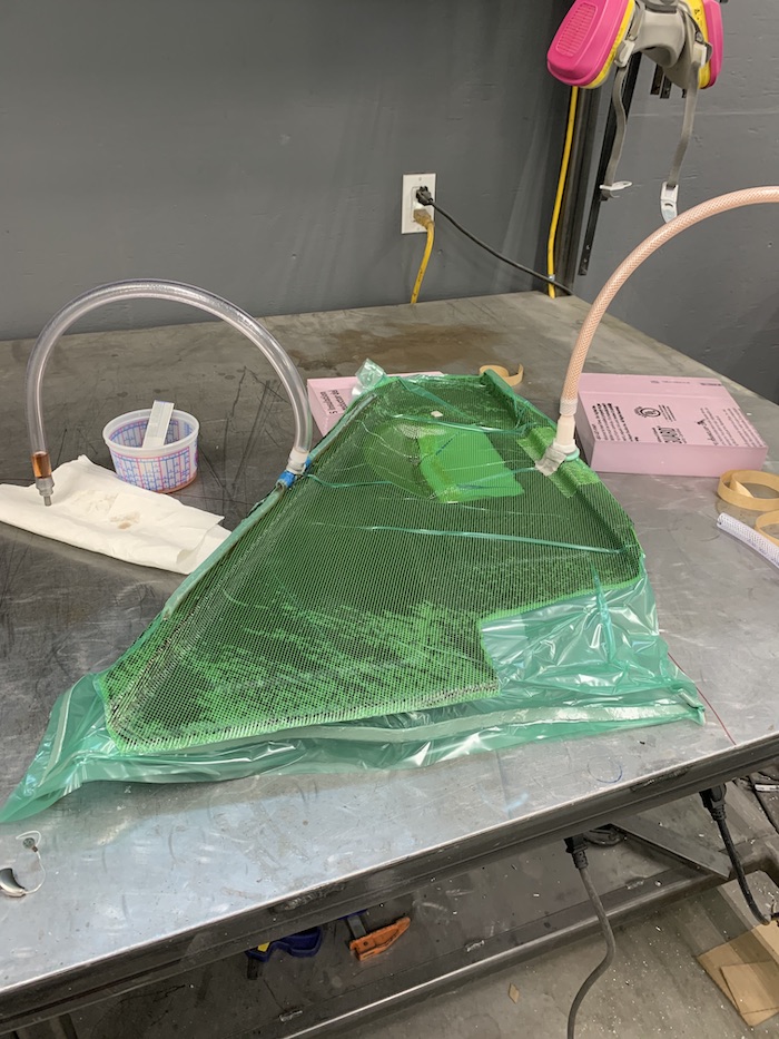
So, guess what peel ply does? It's a release agent. It keeps the mesh and vac bagging from sticking to your part. No peel ply, shit sticks really well - heck, it's epoxied into the part. Here's when I first started trying to see if the stuff would come off.
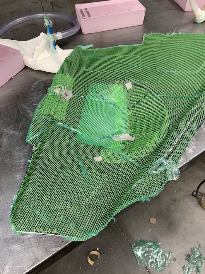
Nope, it doesn't come off - so here's the piece all cleaned up and with as much of the extra stuff off of it that I can get. Fortunately this is an underside so if you don't know it's there, you're not gonna see it unless you're crawling around looking for stuff. I don't think most people would know it's a screw up - I'm gonna say it's a special scatter shielding material if anyone asks.
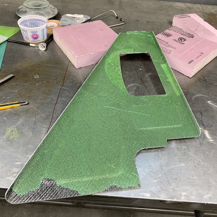
So, wanna ask what else went wrong? Sure you do! Go ahead, ask...
My dumb-ass forgot mold release. It's just brushed onto the mold, nothing special, what have you - just a white liquid that you brush over the mating surface. Did I use it? Nah, of course not!
Know what that does? It pulls all the primer off of the mold and leaves it stuck to the part. SO very glad I have a set of plastic wedges just for removing stuff from molds. Took a bit of work and a lot of swearing at the parts to get them to let each other go. End result is a nicely molded shroud all covered in primer. Shit.
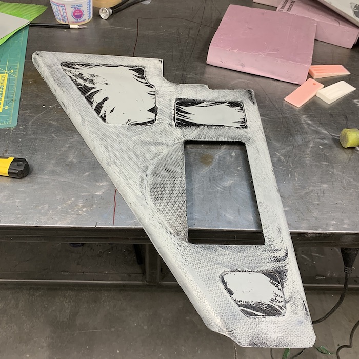
Fortunately it cleaned up really well with a DA sander and some 400 grit. I actually like the sanded look versus clear coated carbon.
The three aluminum inserts will get some sort of pattern punched into them. The smaller rectangular piece was my first attempt. Trying to hold something thin like this in the vice can be sketchy at times - this was one of those times. It moved on me. No biggie - didn't like the lack of detail in the honey-comb cut outs that I saw anyhow. It's a simple part and I already have a new one made.
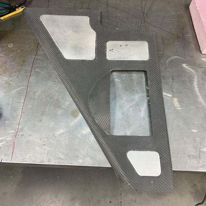
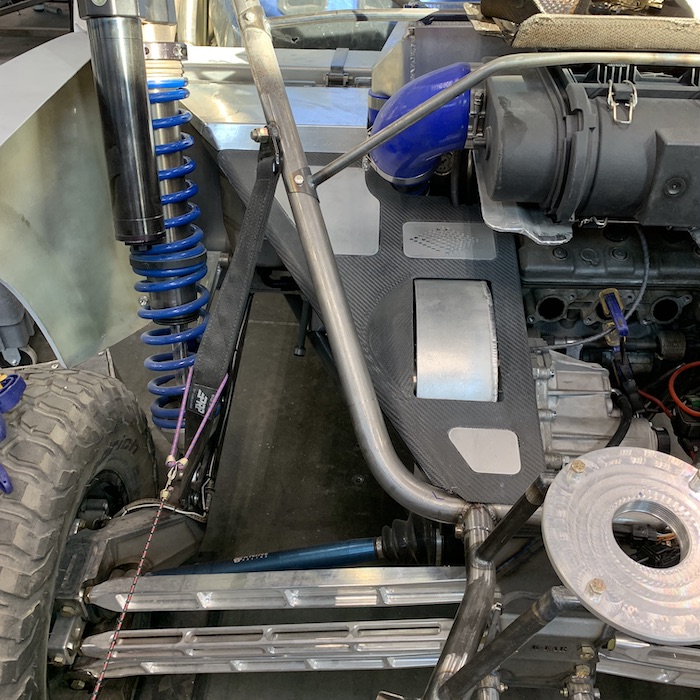
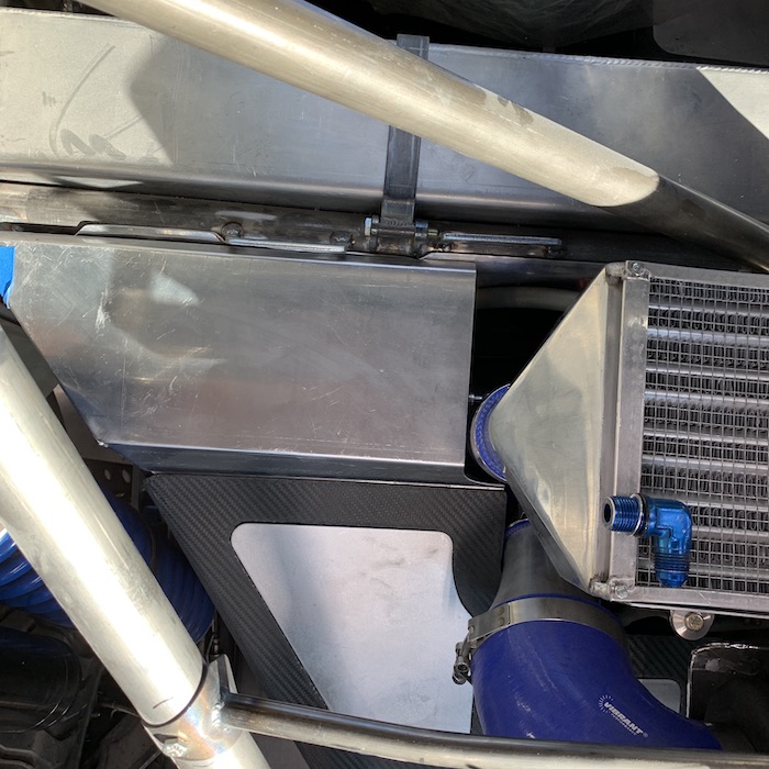
Out with another mold - it fits much better and also blends into the main panel nicely. I was able to use the first one as a pattern that worked out really well.
New res mold next to the first attempt:
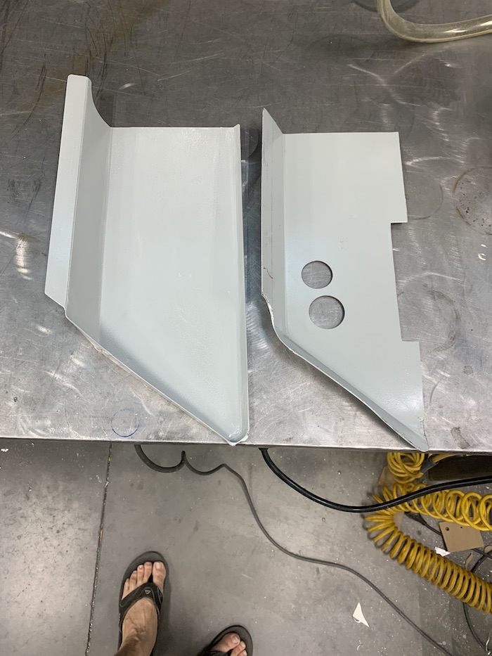
This time, before starting cutting carbon and such, I pulled out the necessities of release the VERY FIRST THING.

Carbon, peel ply (upper left) and the mold all set up for assembly.
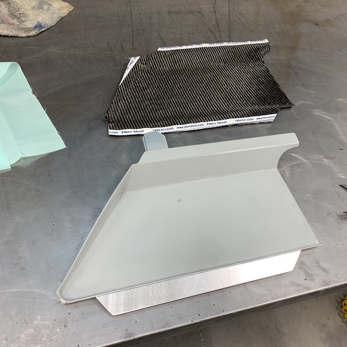
See how you can't see the carbon through the green infusion mesh? That's because Dumb-Ass (me) used peel ply this time.
Infusing in action:
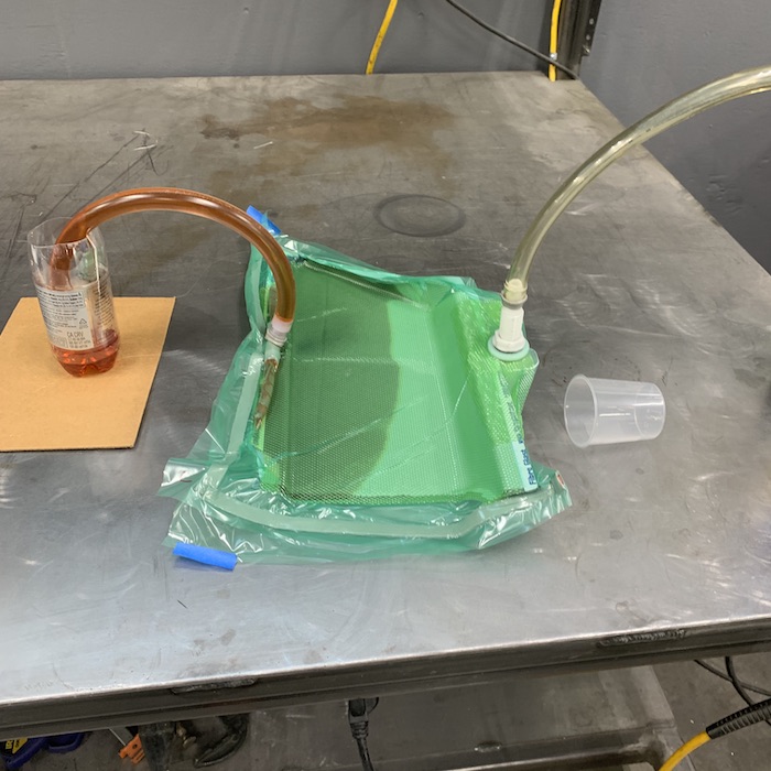
Check this out - this is why we use peel ply. It comes off in one nice piece, leaving the clean carbon underside. Yay.
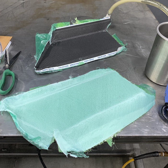
Mold release also makes a big difference. Obviously I didn't get it completely coated but the res cover popped right out and didn't bring all the primer with it like its big brother did.
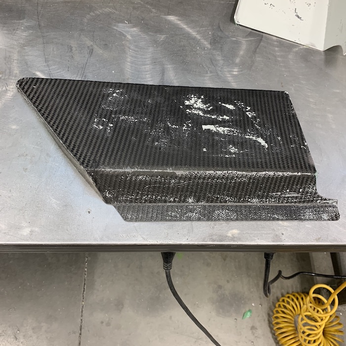
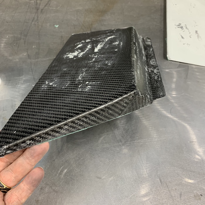
A little more sanding and it now has the same surface as the large piece. Here are the two screwed together:
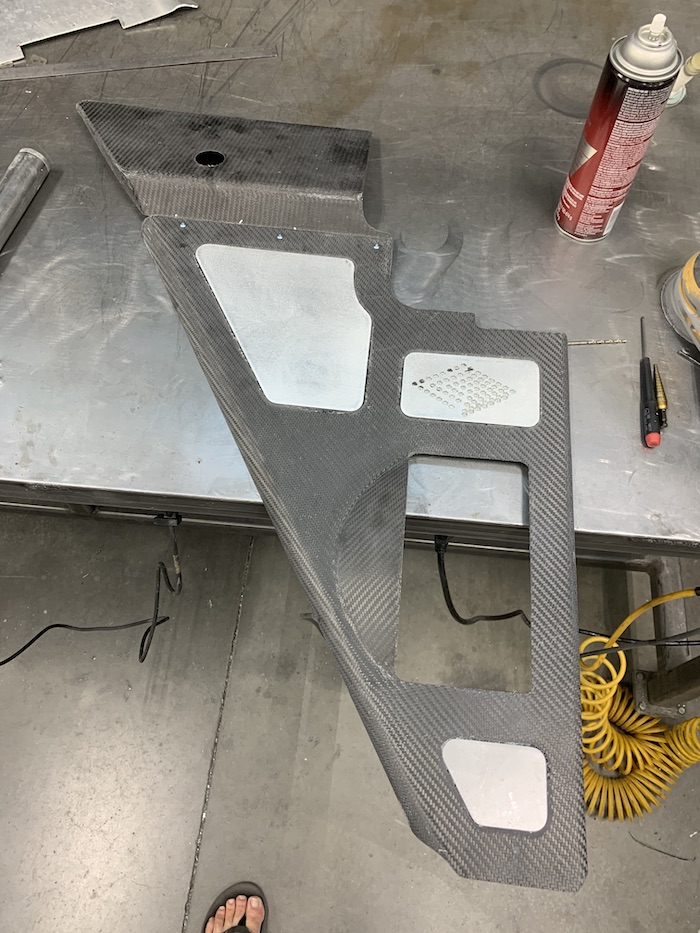
Both parts in place - working on the mounting tabs now.
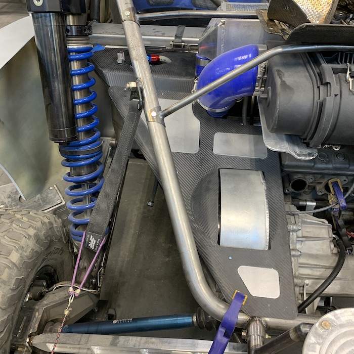
This blend between the two pieces looks SOOOOO much better than the first cobbled setup, don't ya think?

Done for the day. Will get the mounting tabs installed in the next day or so and see what else there is to check off the list.
I'm thinking door inner panels are next.
Oct 28, 2020
Exhaust system is now ceramic coated and ready to run.
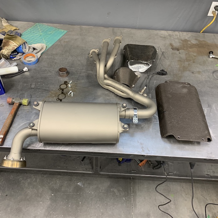
Headers & collector installed along with the bottom half of the header shield.
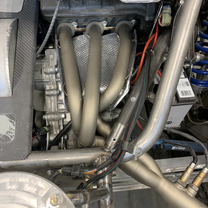
Everything in place - time to go test.
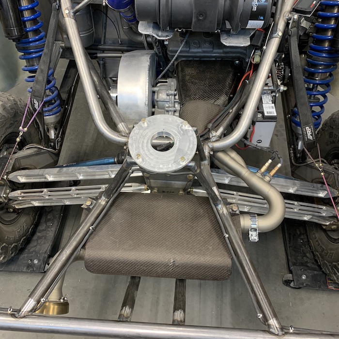
Nov 2, 2020
TheDoc
Pipes look nice, are you going to wrap them, or no need?
Me
Right now, just leaving them as is. I did a quick run down the street and when I came back the shields were definitely on the warm side (could smell 'em) and were really warm to the touch so we'll see how they do.
---------------
Had planned on heading out and getting the first test runs and starting to get tuning figured out but alas, our Halloween party put me in serious couch mode for the day.
Since I'd planned on going out testing I put the harnesses in. Nobody but me seems to like the TeamTech Jetpilot harnesses that I run but eh, I do and it's my ride.
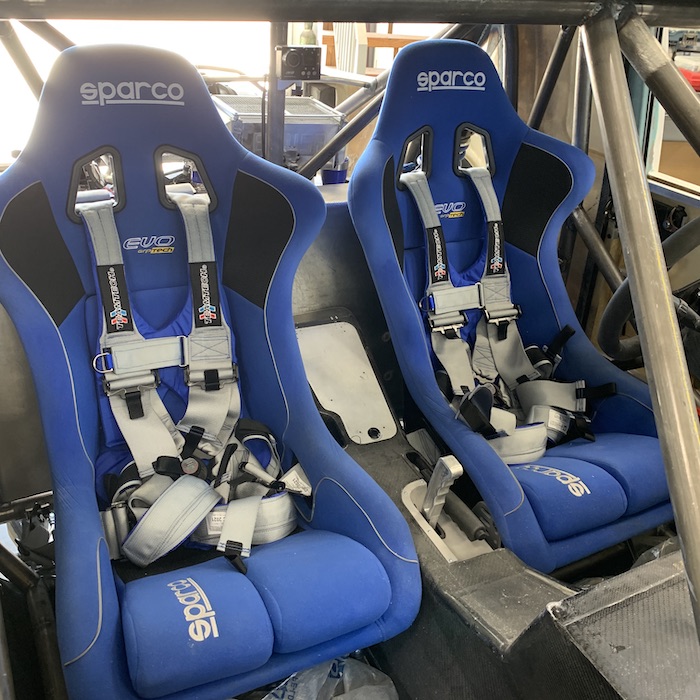
I'll get her out this week.
Nov 17, 2020
Stories to tell, fires to put out.
Updates a bit later.
Nov 17, 2020
Last week I thought I had water temp sensor go bad. Last time I messed with the Mini-Raptor (week or so before) it was not a displayed 608F in my shop. It was 75ish.
It worked fine, then it didn't. Shouldn't have gone bad, it's a new, high quality piece.
Checked plug in points, jumper cable, etc., looking for an issue. Nothing, and it's still 608F (surprisingly comfy) according to the dash.
Had a spare temp sensor so I unplugged the one in the manifold and plugged the spare into the lead.
Boom, dash displays correctly right off the bat. 75Fish
Shit... The sensor's a PITA to get too. Time to walk away.
Fast forward three or four days: While starting to replace sensor today, I unplugged the installed one (had put things back) and decided to stick the new one on to see what it reads.
608F! WTF??? This one can't be bad too! It worked last week when I was diagnosing!
I dropped the spare sensor, letting it dangle on the jumper and tada, room temp readings.
Oh f**k yeah!!! It's not bad sensor! It's in the plug end. I pulled the plug, inspected the lines and found a cold solder joint.
It's fixed. 22 gauge wire is tender...
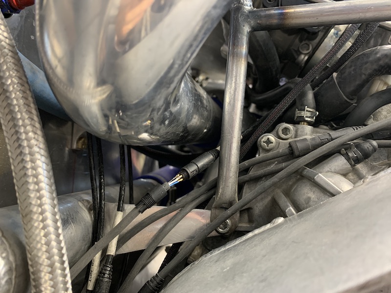
Ahhhhh, these little victories feel really good after so many crotch shots!
Got my brake pressure sensor installed too.
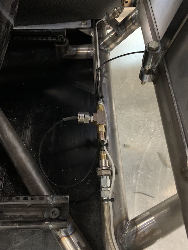
And of course it's not playing nicely. Thinking there's an air bubble at sensor maybe? Shouldn't be. The dash says I have 1680 lbs of pressure at 0 brake. It also says I have 1680 when I push full pedal.
Might be a channel programming thing too. It shouldn't be telling me there's any pressure.
Played with the computer watching live feed and there is no response from brake input.
Unplugged and got a change on the live feed so something is talking, just not in the right language.
I WILL be checking the jumper for issues. (I'm trainable!)
I started CSIing the plug and sure enough, I'd wired it mirror to what it should be. My plug assembly notes say "pins facing down" on the diagram - uh, which pins? I made this one quite a while after the others so obviously I chose the wrong pins to point down during assembly. Quick solder iron magic and tada, another working plug with a sensor that gives me correct info. Cool. One more little picky ass detail to attention done.
Testing begins tomorrow (Friday, November 13th, 2020 - what could go wrong?). My wife is going to go out in our RZR in case I need a tow and will video suspension if the engine/drive train plays nice.
-------------
Ended up not going out on Friday. Got involved in crap around the house, did some other little shit on the Mini. I'll go out on Sunday. Saturday already had dirt bike plans).
Sunday. Ugh... We'd gone to a b-day partay Sat night and well, let's just stay I was moving a tad sloth like in the morning. Got a call from my buddy Jay (who was spending the weekend where I was thinking I'd go test) that he was headed home. Cancel Sunday.
I WILL GO ON MONDAY!!!
We ended up going out on a 60 mile RZR ride Sunday afternoon. Went through a wash that's right off of a main road, easy access, flat, can park right off the side of the road. I'd forgotten about this area (not fun on a bike so I don't go there). This is PERFECT testing terrain. DAMN IT I AM GOING OUT ON MONDAY!!!
Monday shows up. I AM GOING TESTING!!
Loaded the Mini-Raptor up in the van for the first time - it fits almost exactly like the old Deztaz did. Wheels up against my bike chalks, rear doors against rear bumper. Nice, perfectly tight fit.
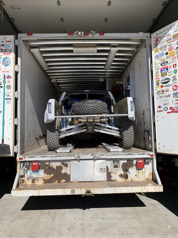
Got to the testing area and set up my pit:
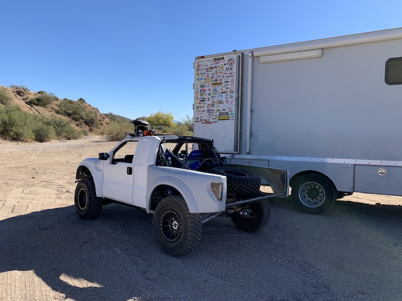
Plugged the computer in, started trying to get the Autotune running whist the MR sat there and warmed up. I messed around a bit, I think I got things happening, maybe?
I did have the realization that I was only going to get 5 psi of boost. The blow off valve is set at 5. My pulleys are 8. One turn in on the preload spring. Pressure is up - but I don't know to what - too busy watching shit in front of me to look at gauges. Not sure why (because it's electronics and they're a pain in the ass) but the data logger only ran 6 seconds, not 6 minutes. So I don't know what my boost is but it's more - the engine is now trying to get to full rev.
The long awaited Mini-Raptor's first real run is in the books.
Chassis looks VERY promising. Like F**K YEAH promising. Handling is excellent. Really easy to drive and it's not even remotely set up yet.
I have to laugh at myself - Testing K-fab style: Point it in the right direction and STAB THE FUN PEDAL!!! Let's see what breaks.
It had been sitting there idling in the pit area while I was dicking with the PowerCommander. Everything was up to temp when I got buckled in, so, I rolled out of the pit shade spot, into the wash and stepped on it.
Figured if it was gonna go poof-ka-boom, may as well make it do it now. SOLID performance!
I went out as far as I was willing to walk back if I had to and then found a place to turn around.
I didn't drive it easy until my second return run when I saw the hood bouncing. Mounting studs came loose - I think they pulled out of the bulkhead as it's thin shit. I need to tack nuts in place where they're mounted instead of just jamb nuts against the bulkhead webbing.
I put it in 4x4 when I turn around back at the van (about 3:20) to see what it was like that way. Goes more where you point it, but not needed to play at all. Really just made sure it works - yup, it works.
Needs more rebound damping - it wants to hop up after compressions, like out of deep/banked corners. First compression zone may be a tad stiff (really chattery over washboard - maybe... it's really rough there) and I don't think it's stiff enough for the big hits. I just have everything at 2 turns out for a base point, though.
That gets played with once I get the fire damage fixed and it running safely again.
Right thumb stays outta da wheel. Need to have a discussion with the left one. You're not supposed to be inside that thing.
Overall I'm very pleased with the results. The setback of instantaneous combustion is a pain in the ass, but hey, it's been the theme of the Mini-Raptor.
SHE LIVES!!!
The fire, on the other hand was a bit of a bummer.
My exhaust heat shields are not heat shields, they are flamers.
After my first little two legged jaunts, I came back in to attend to the loose hood. Sat there in the shade of the van (end of video), poking through the dash stuff, looking at info with it idling and I smell something. Look over my shoulder and there's black smoke rolling out from under the air filter.
OH SHIT!!!
Hopped out, grabbed the extinguisher in van (been there 14 yrs waiting on an event such as this) and put the shit out.
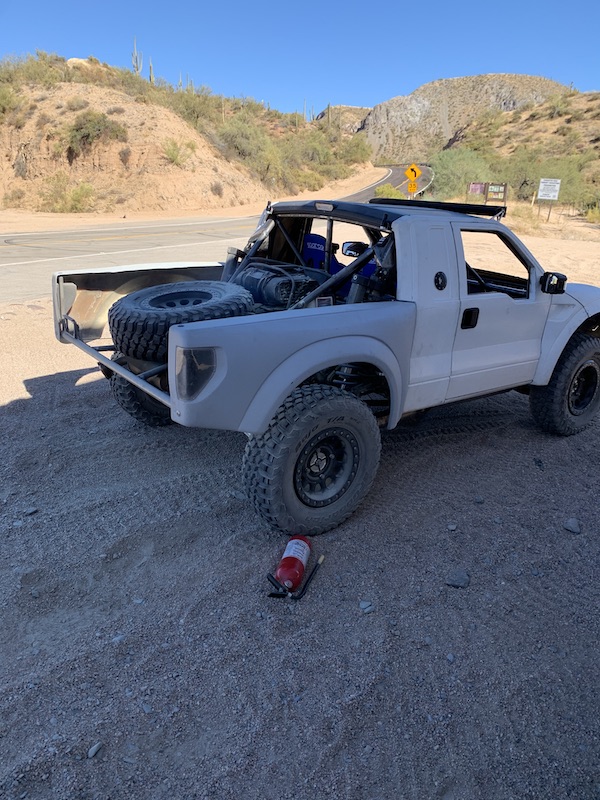
Made loading a bit of a challenge. Had to back the van up to the front of the Mini-Raptor, and then use the winch to pull it up into the van. Melted throttle cable made for no driving.
Hood came loose where it's attached to the bulkhead. You can see it in the video when I turn around and start driving slowly.
That's all I've seen that's broken other than the burnt up stuff. Not something you want to see behind you. Fire BAD!!!
Now I have a mess to clean up and wonder what sort of wire harness damage has been done. Throttle cable's toast and I could see the cam cover gasket sticking out from the head.
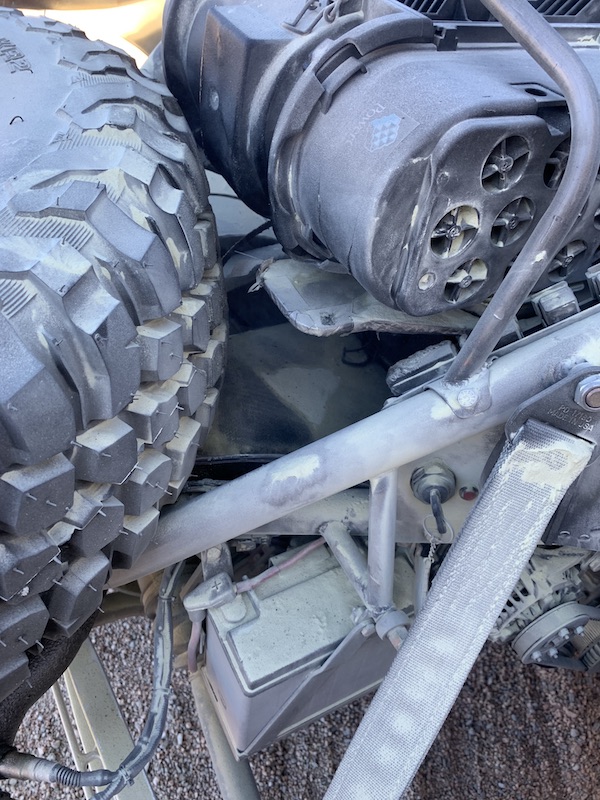
Two racing steps forward, one pit fire back. Still have to clean things up and starting figuring out what's toast (ha! pun intended) and not.
SHE LIVES!!!!
It really handles well...
Nov 19, 2020
TheDoc
Bugger about the BBQ, and no invite. so what does OEM say about their heatshield product?
Great update with heaps of input, was wondering where you had wheely bin. HAHAHAHA 8)
Me
Yeah, was bummed I had no shrimp for the barbie. Not sure the epoxy smoke would be the right seasoning...
Yamaha has that quilted foil stuff around them. I thought I kept it but ??? Will probably order (at least look at on the parts fiche) one to see how to adapt. Checked the wire harness - US$550 from dealer. Found one new in box on eBay for 200 last night and hit the order button.
Looks like a new airbox is in order. I found melted stuff yesterday during a quick look over. Will know more today.
jimmyg
Ozzy humor at its best.
Me
Some of my favorite type!
I must have been Ozzy in a previous lifetime. I can operate a right hand drive car, shift with my left hand know “tight left, wide right”. I'd make a great postal carrier - feel right at home in the left side of a car.
I've also developed the ability to understand alcohol lace Ozzy speak, which is an art of its own.
One day I'll be down there, annoying Talon and family. I owe him that.
Nov 20, 2020
Fire bad
Over the years I've seen small ones, like I had, to fully engulfed, “Break out the hot dogs and marshmallows! We got us a fire!”
Last one I saw was a turbo RZR out here on one of my favorite dirt trails last year (maybe two ago?). Four people standing there, looking very sad, staring at a smoldering pile of melted plastic and metal.
They never end up good.
Parts list ordered yesterday:
New OEM cam cover gasket
New Donaldson air filtration box (shit)
New PowerCommander Auto Tune unit module (shit, shit)
eBay Yamaha Nytro main wire harness (oh boy, more wire work! shit, shit, shit)
eBay Yamaha Nytro efi harness (plug-n-play)
eBay Yamaha Nytro coil packs (three for $99 versus new for $115 each)
eBay Yamaha Nytro OEM header heat shields, upper & lower. If Yamaha can put the exhaust directly under a plastic seat and not have fires something says they did it right.
I see other crispy wires - expect them to be part of my harness assembly.
Gonna dive in fully today and start cleaning and disassembling. Anywhere the extinguisher powder hit hot stuff it seems to have turned into a sticky goo - think very thick honey. Fortunately it appears to be water soluble.
Nov 22, 2020
Pulled stuff off. What a mess!
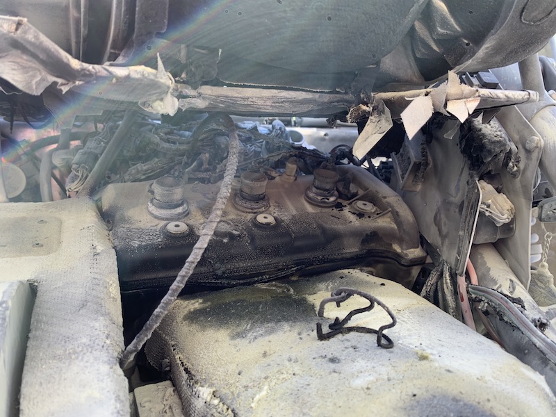
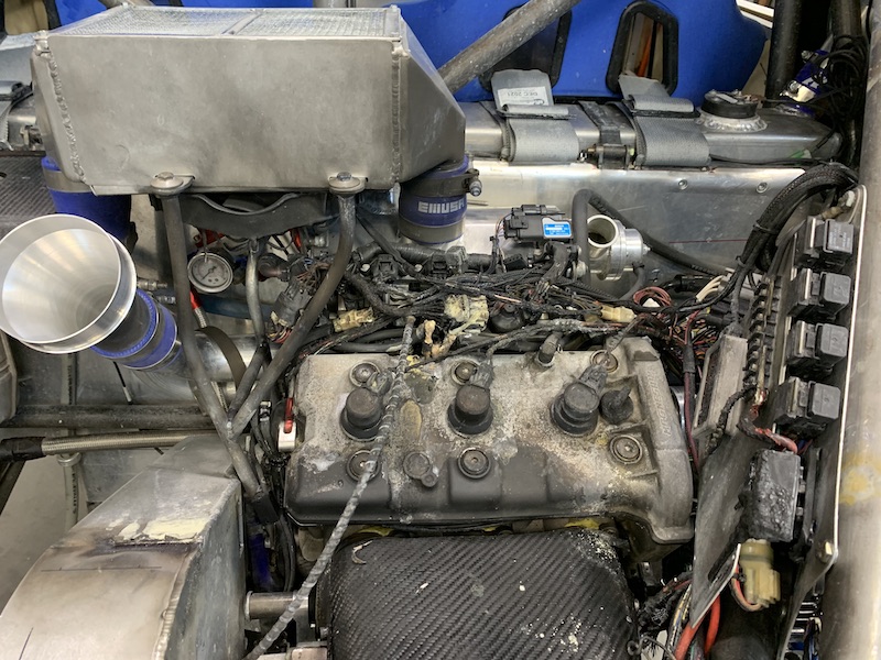
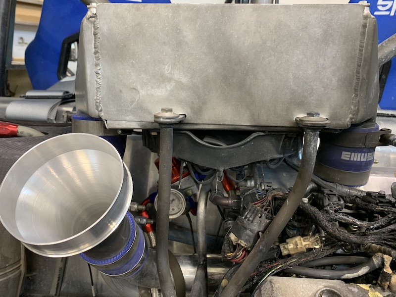
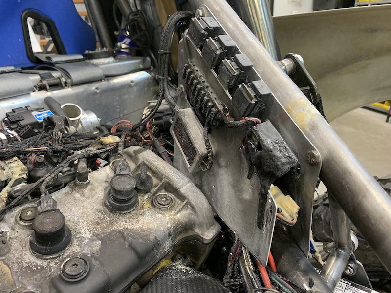
Made new supports for the hood stand offs. It think just the 1/4" rods sticking up with the ability to flex around lead to part of the failure of them. I also think I may not have had the rear mount completely tight (there's SO much stuff in here, knowing and keeping track of what's been tightened, especially months ago, is a bit of a bitch). These spread the load out a lot better. I'm also redoing the front mounts. The 3/8" (9.5mm) bar that I used looks to be on the weak side as I had one piece actually snap.

So it's wait for parts and then start more disassembly so I can start putting stuff back in that's not toast.
Dec 16, 2020
Here's the culprit behind the fire.
The two layers of carbon and the layer of fiberglass veil in between survived just fine. No epoxy to be found:
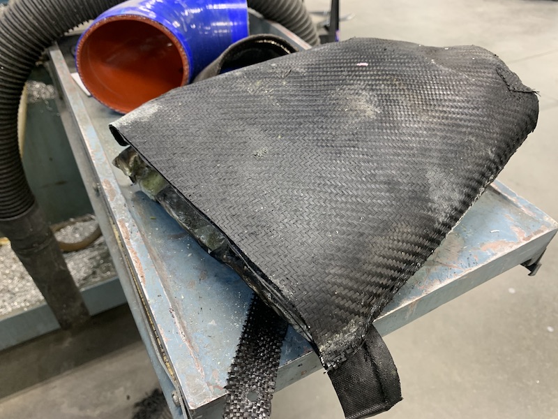
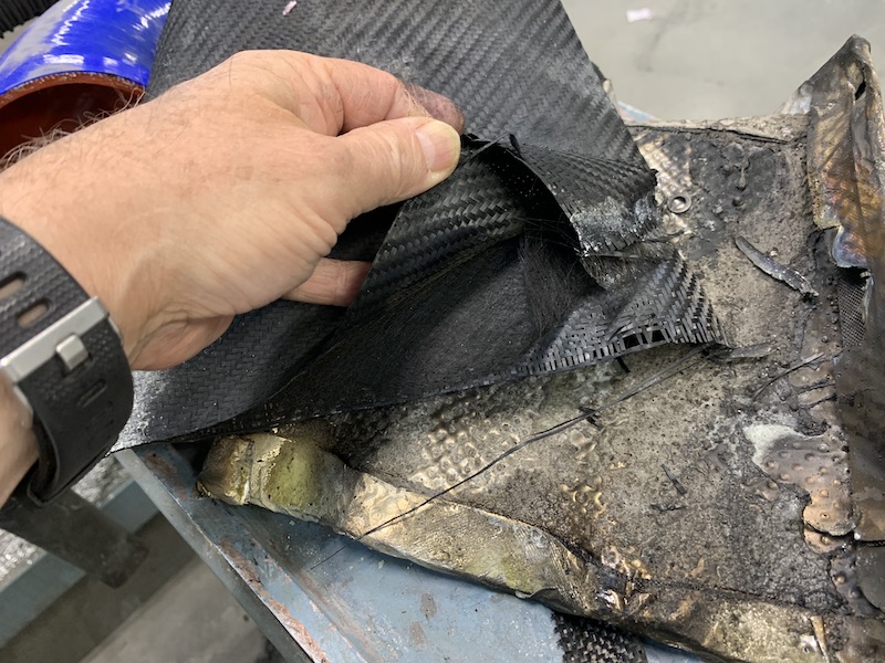
eBay cam cover bead blasted and painted to match the mag cover.
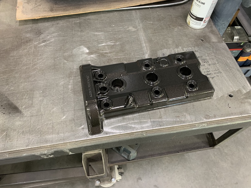
I got the intercooler cleaned up (luckily no damage to the little fins inside) and put a new fan on it. (no pix)
New airbox modded (had to remove some mounting bosses that are not used - for mounting vertically) and new heat shield done - the stuff worked pretty well. The way the flames were able to move was what cooked the other airbox. I'm planning on a bit more shielding.
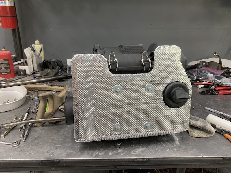

Headers cleaned up nicely.
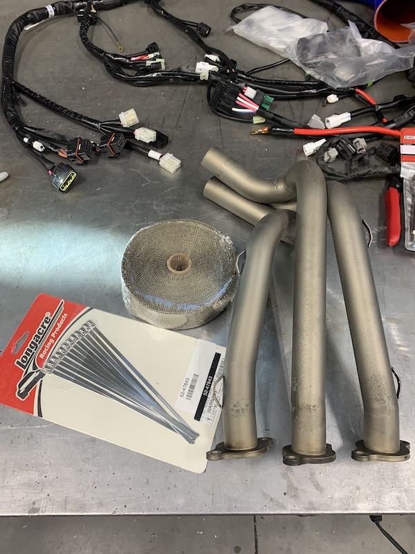
And they got a wrapping of header tape (which I SHOULD HAVE DONE ALREADY! Dumbass).
I have one of the OEM heat shields on the bench and I'm waiting on the top half - will do a bit of forming and get them installed. If they can keep the plastic seat of a sled from going poof, they should be able to do the job here. I also got a little 4" fan that will blow air through the shield and over the headers any time the engine's running. Insurance....
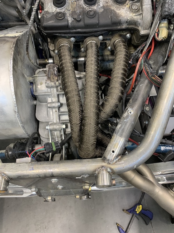
Diving into the wire harness. It's a total loss but I'll be able to copy it pretty easily. Want to modify a couple things anyhow - the AiM system will be plug in instead of spliced this time. May move some of the components around too. We'll see.
The deeper I got into tearing things apart the happier I am - 90% is wire harness.
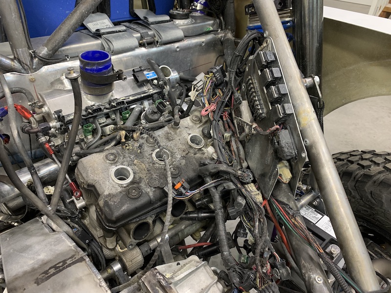
Gratuitous photo shot - walked past it and thought "that looks good!" so I snapped a pic.
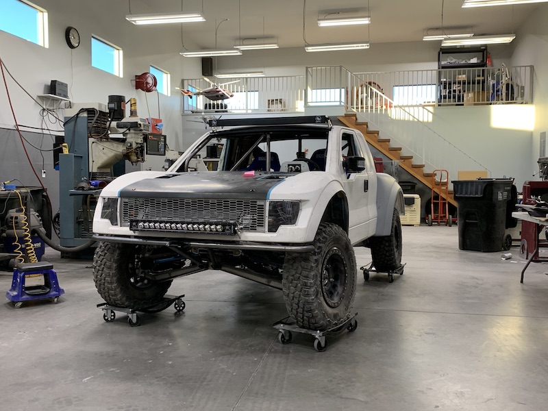
Dec 22, 2020
Quick update:
Clean up is done - putting things back together now.
Where the cam cover drooped it let fire extinguisher crap get under and into the top of the head. Fortunately just in the cavities and it doesn't appear that any got farther than what's seen in the picture. I took a lot of time and carefully cleaned it all up. Good thing is that the next place for the oil to go is through the filter so anything I missed won't go thru the engine, just into the filter.
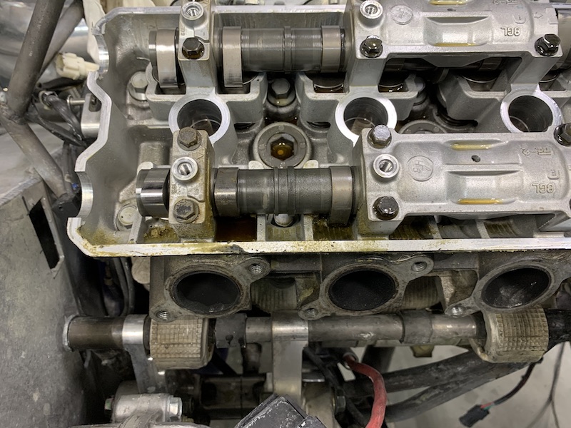
My burnt up harness sitting next to an OEM Nytro harness. I'll get a couple pix of just how much of the harness I don't use (if I can get my phone to take pix... the stabilization system has taken a shit so I get the jelly pix. Have to whack the phone and hope it catches focus. Waiting on parts to fix it)
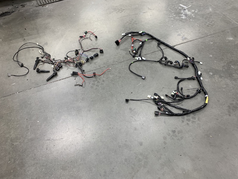
And the harness all naked and ready for disassembly.
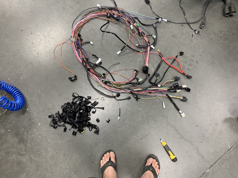
Presently working on getting all the harness stuff to fit onto the Mini-Raptor's platform. I have all the signal and sensor wires located and run, now it's get all the ground and common wires rerouted and set. Harness is gonna look really good when I'm done. I kept all the OEM covers/shields so no zip tied bundles, just smooth, insulated and covered like it's OEM. (I hope).
Back to the shop with me. Spent 5 hours on wiring yesterday and if someone were to walk down and look at it they'd think I'd just thrown a pile o' wires on top of the engine.
Dec 31, 2020
Happy New Year!!!
Planning on starting ours with a RUNNING vehicle. (key word - planning....)
Been busy with life, holiday, b-day - all that stuff that gets in the way of shop time so I've not had a chance to do much and to boot, my phone's camera was on the fritz. I didn't know that hard mounting it to your motocross bike's handlebars would finally shake the stabilization out of it. All I could take for the past couple of weeks was jelly looking photos.
Ordered a component from Dyno-Jet a couple of weeks ago - it was on a Friday, late in the afternoon. I'll be damned if it didn't show up the next day. Las Vegas is about 5 hours from me and the postal service did a bang up job getting the auto tune to me.
So I called and asked about getting a wire harness for my PCV (since I'm not scared of going inside the box - figured I'd just solder a new one in place). Nope, but they'll sell you new at a discount if you send in old.
On the 18th I boxed up the burnt up PCV and Autotune (going to return the purchased one and save a bit of coin). Put the burnt items in a Priority mail box (should be 2 days max) and off to the post office I went.
I expected to hear from Dyno-Jet pretty quickly, as their customer service is excellent. Nothing... Three days, nothing. Better check the package tracking. What the ???? It's just left Phoenix? Okay, holiday mail service is dorked so...
Couple more days, still nothing from Dyno-Jet. Checked tracking again. Why in the world has my box gone from Phoenix to Houston? Wrong direction and off by about 1200 miles.
Got an e-mail yesterday from Dyno-Jet saying they have my box, things qualify for replacement at discount I have to make a phone call in a bit (not open yet). I'll probably have the components early next week.
Throttle cable - it went poof (more like drip) too. Local place that made them is gone but I actually found the place in Kommiefornia that bought all the local place's assembly equipment. A couple of phone calls, a few discussions on how to measure, pics taken mods made. New cable arrived promptly and is completely incorrect. More calls, more measurements and correct part numbers (now that I understand the nomenclature of the number). Hoping it arrives today.
Anyhow, when I've had a chance I've chased electron highways (wires).
Don't need this (I now have five of this section - the Briggs used the same thing):
Trying to copy this (well, what's left of it) has turned out to be a bitch.
Here's what I have so far and it SHOULD work:
But of course it doesn't. It doesn't even make a click or let the smoke out or... Nada, nuttin', nope, not playing nicely. Shit.
So it's wrap up the day in the shop and bring the harness, service manual and pin removal tool up to the house and start my homework. Made copies of the wire diagram and started marking stuff off as I verified it was there. Seems like everything is in proper order.
Lots of junctions for common things such as switched power, constant power, grounds: They're little six place plugs that have a piece that slides down into them and makes contact. 11 of them to be precise... And there it is (oh how I hope)! I managed to miss sticking the contact piece into this one.
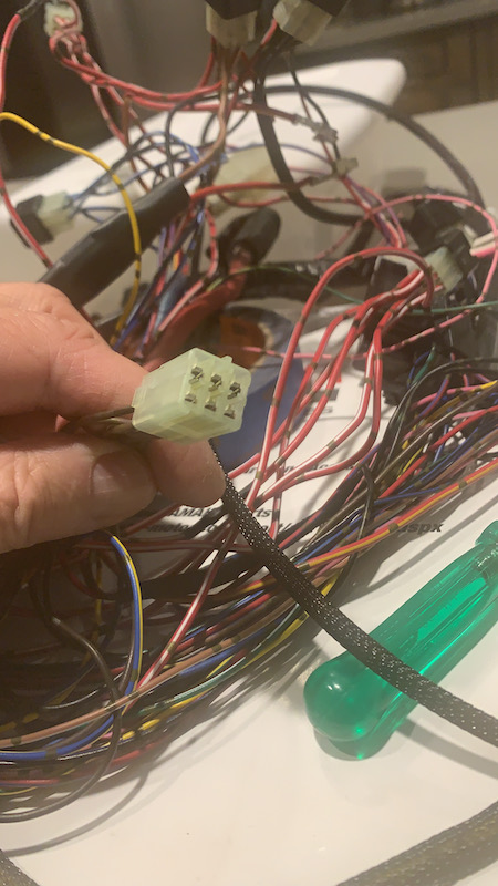
I'll be headed down to stick a connector into the plug, put the harness back in and see if I have life.
Aaannnndd nothing!
Still no click, pop, smoke... nuttin...
Shit
2020 can go away!
Harness in semi disassembly and once again, chasing wire by wire.
Me brain and eyes hurt and I really don't want to go to dinner tonight. I wanna hold the couch down until about 10 or so, go to bed and then be happy tomorrow is here.
Will report back later - more than likely next year.
This concludes the building that happened up through the end of 2020. Click on the link below to be taken to what happens in 2021.
The Mini-Raptor build during 2021
Return Home