

The Mini-Raptor Build 2016
|
2016 build 2017 build 2018 build 2019 build 2020 build 2021 build 2022 build 2023 build 2024 build 2025 build |
 |
 |
 |
 |
January 30, 2016
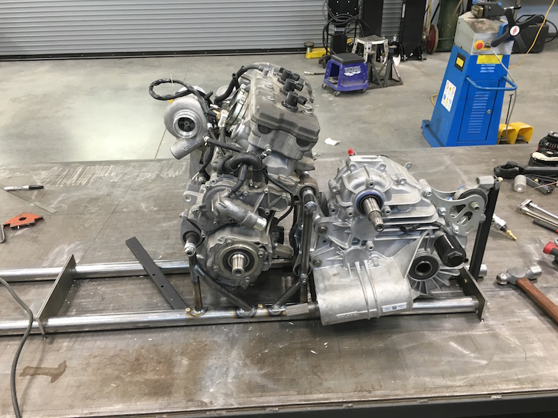
While Flyer and Justin work on that, I've started working on the engine/tranny mounting system. The drivetrain will be one modular drop in unit. I've 85% designed the piece that attaches them together. It'll hold them parallel using the trans mounts and the rear engine mounts and I'll incorporate threaded adjusters to allow left/right movement of the trans for proper clutch alignment.
Feb 12, 2016
Been busy this week - finally got free time to myself and have been making a bunch of chips.
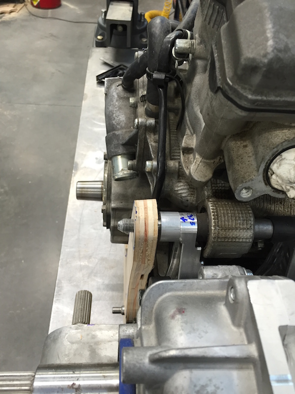
I've started working on the mount that will go between the engine and the XP transmission. I'm using the long bolt that holds the engine in the sled to locate and support the trans. It makes everything nice and parallel and I can slide the trans back and forth on it to align the clutches. It ended up requiring two different prototyping mounts to get it all figured out. I thought I had pix, but I can't seem to find them. I was waiting on some sled parts (adjustable mounting pieces) before I finished the trans/engine mount up. They showed up yesterday, but I've already moved onto the next aspect of this engine stuff.
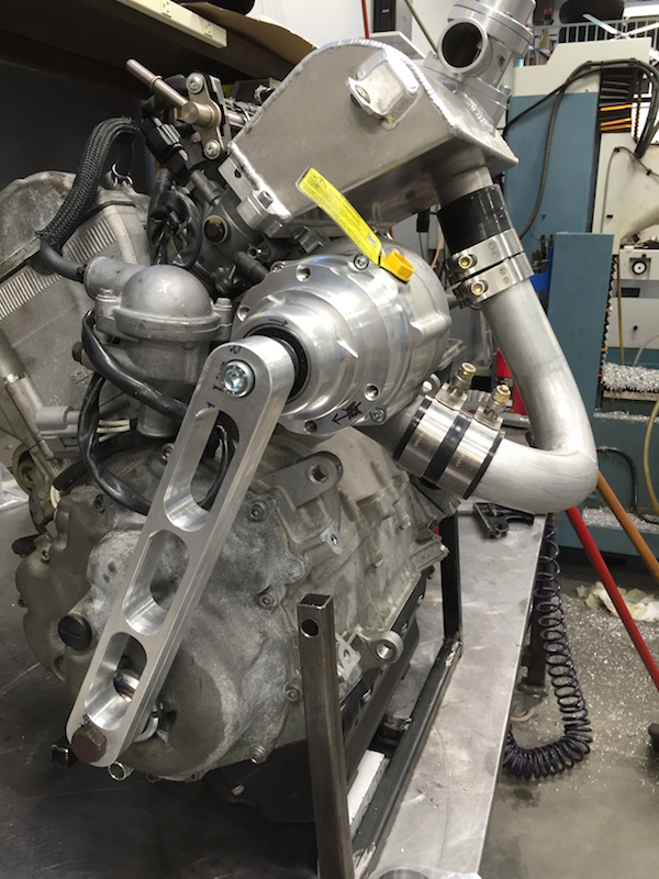
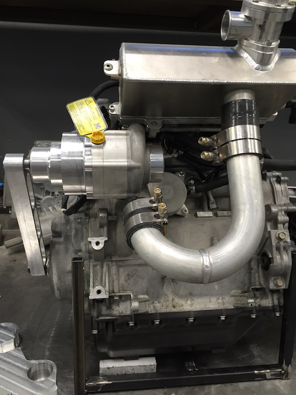
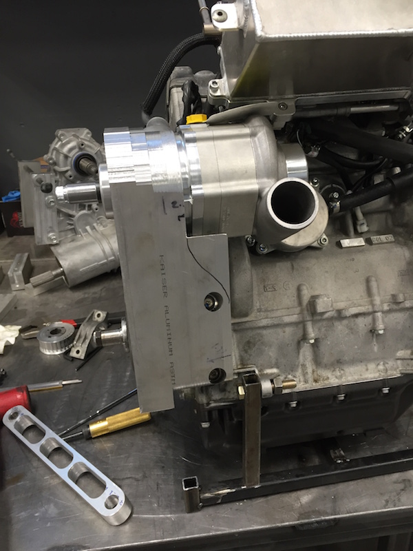
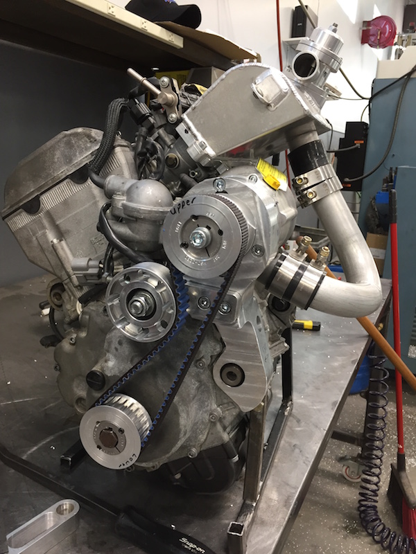
That next aspect would be the supercharger mount. In the sled, the supercharger is mounted to a side bulkhead that the engine's mounted to. It's a big, stiff piece in the sled.
Trying to figure out how to support the supercharger has been a challenge. I've decided to use one of the stock engine mounting locations. I kinda figure if the cases can handle the forces the engine is putting out, it should be able to handle the supercharger's belt tension during operation. Guess we'll see, eh?
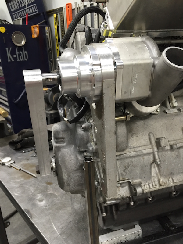
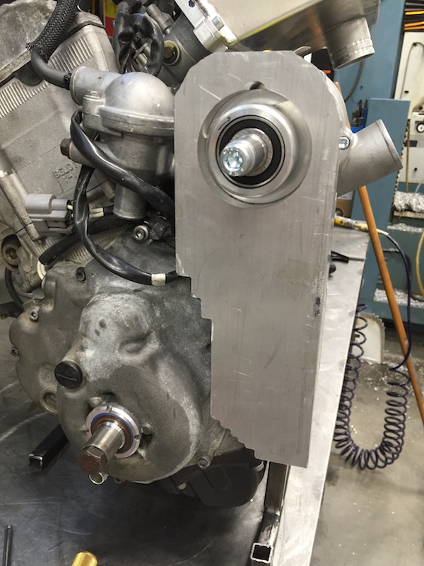
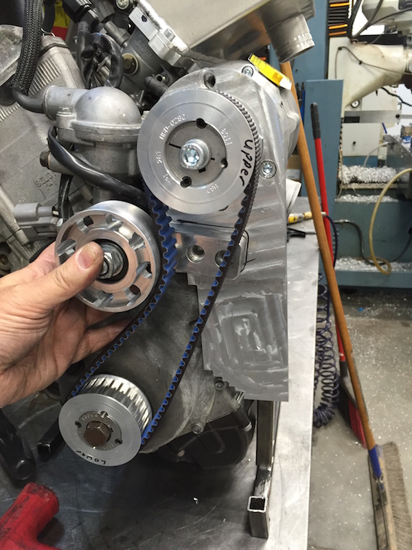
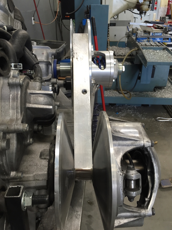
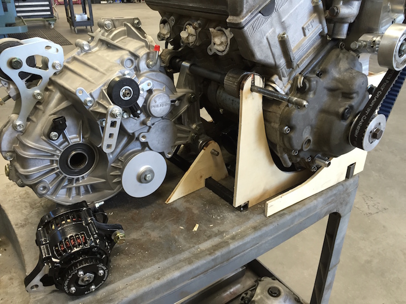
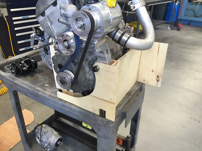
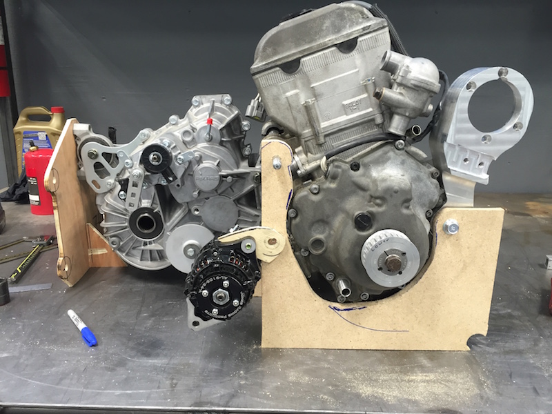
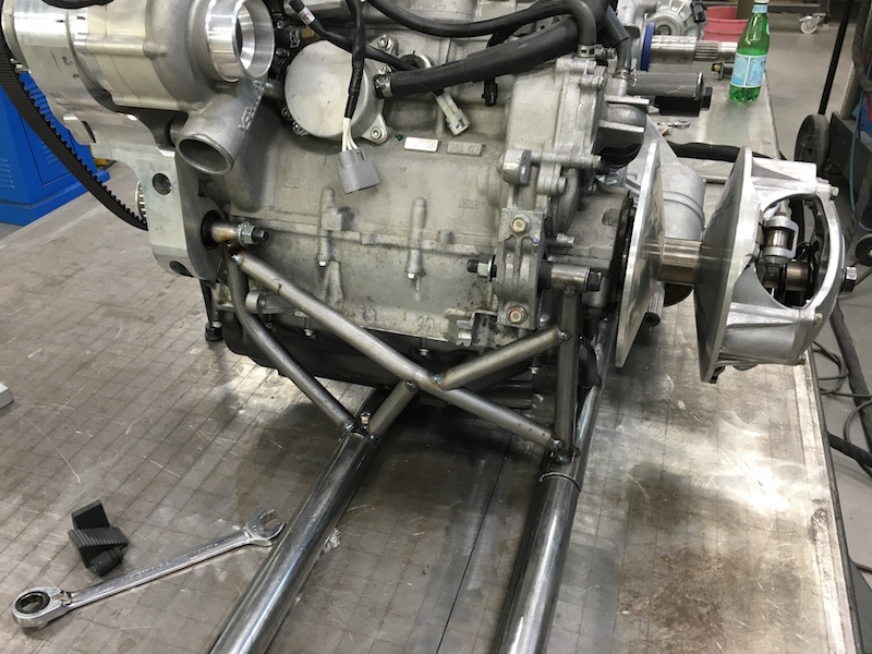
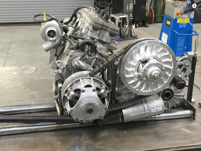
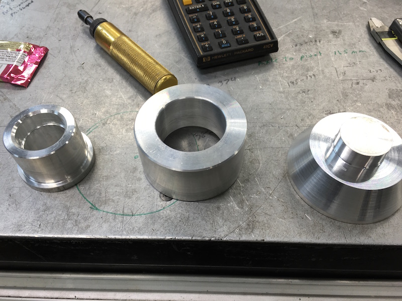
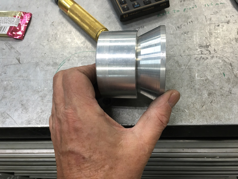
The pulley center to center spacing in the sled is 9.5" So that was my magic number. I made a bar that held the supercharger off the end of the crank in it's correct location. The plumbing helped line everything up pretty well too. The bar's nice tight fit and I'm getting minimal deflection of the s/c as it's hanging off in the air.
 |
 |
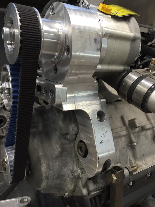
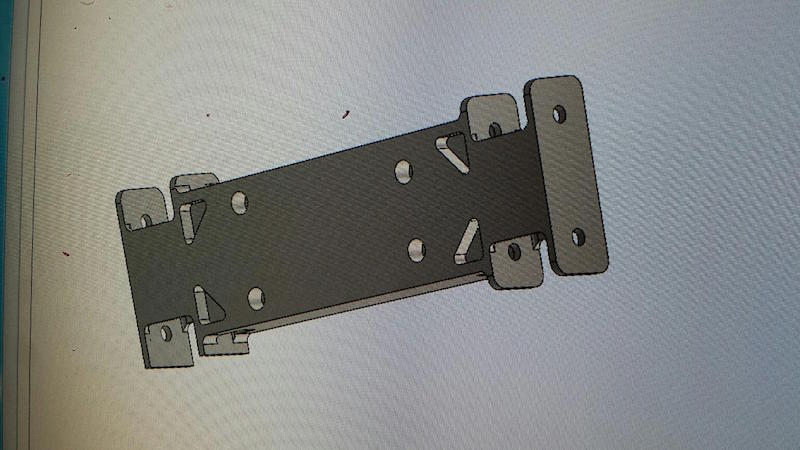
Next it was try to figure out how to hold the darned thing in place. I ended up making a plate that sort of located things where they needed to be.
 |
 |
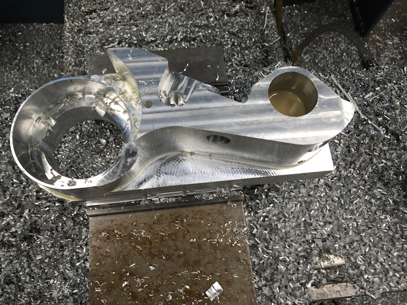
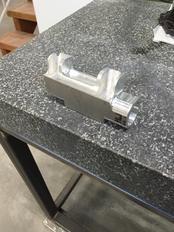
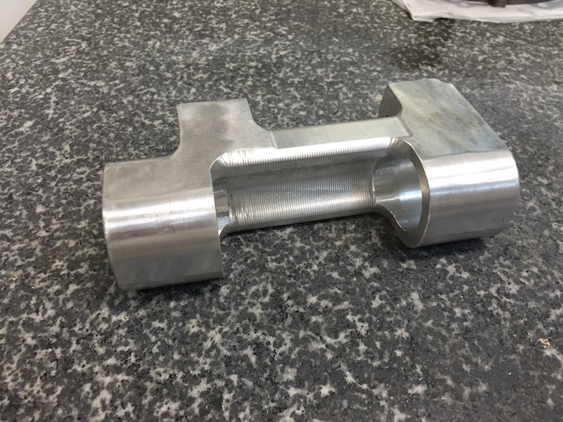
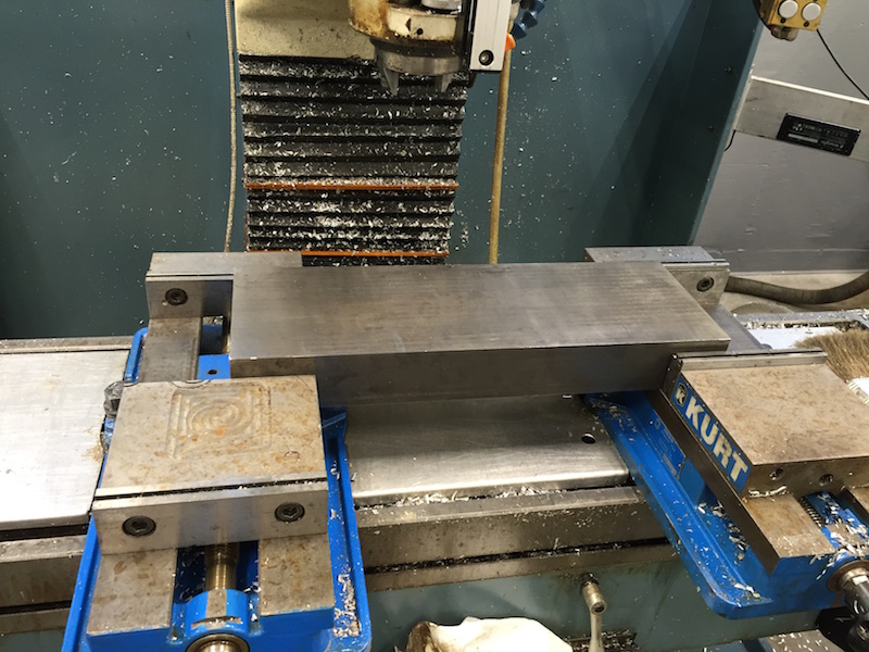
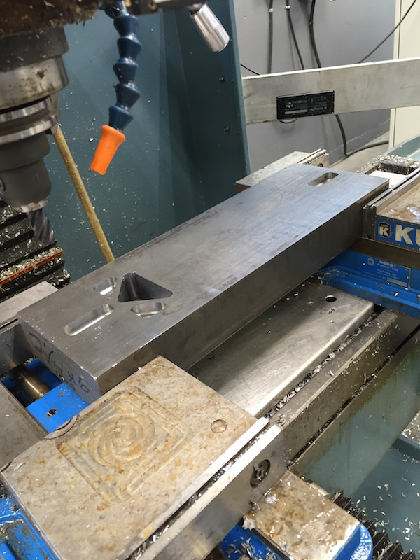
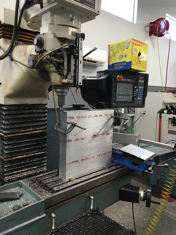
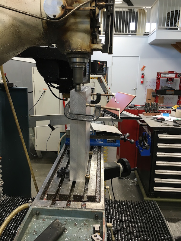
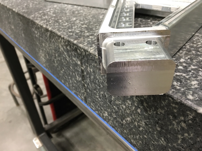
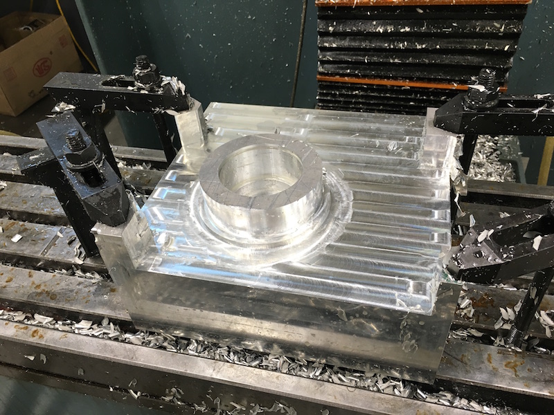
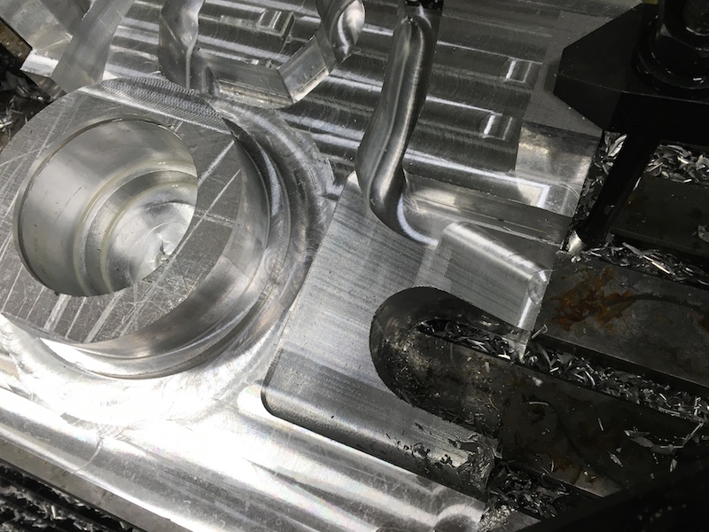
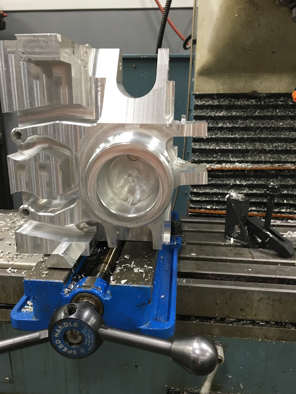
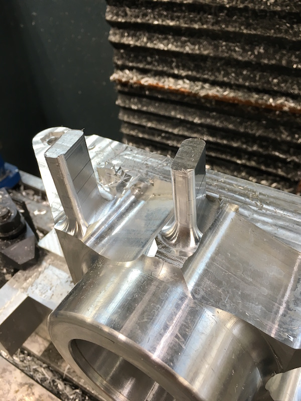
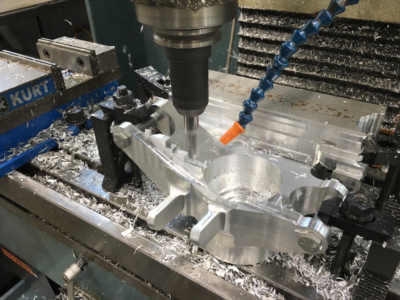
I started out with a 4" x 4" x 11" piece of billet and started hacking away.
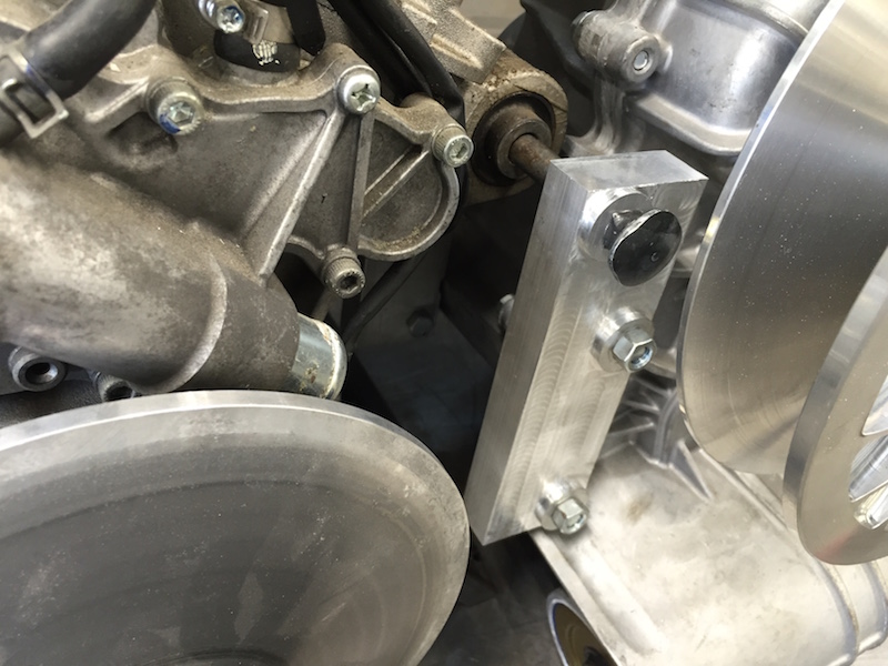
I got the basic shape of the side that mounts to the engine figured out, more or less. Still had a couple of pockets and clearance areas to attend to. The hole on the left is where the rubber piece in the stock mount will get pressed into.
This was last night's stopping point:
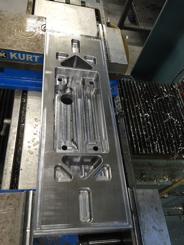
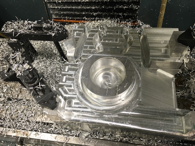
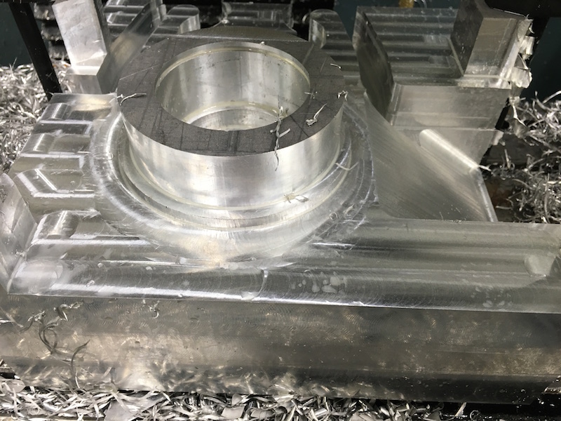
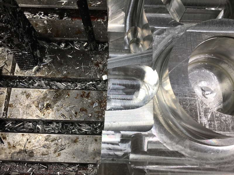
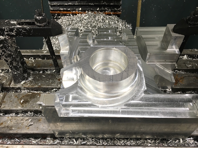
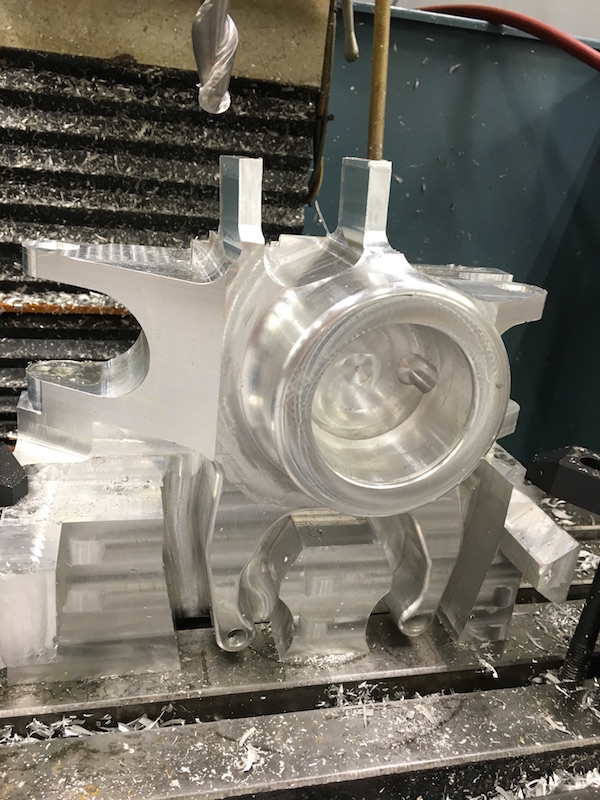
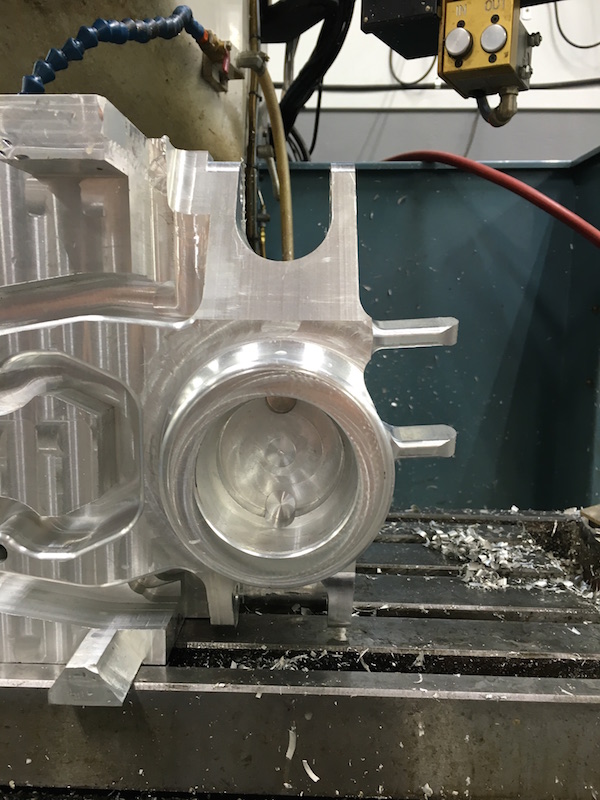
Today I got the main holes and locating bosses cut in along with removing a bunch of extra material that was in the way. The fit ended up being really darned good - especially considering this has been in and out of the mill a dozen times or so. I have a really good locating hole that's proven to keep everything within a few thou. Tolerance isn't overly critical since the belt has play and adjustment.
 |
 |
I'm working on cutting out the body now. Once this side is done (there's quite a bit to remove), I'll turn it over and tackle the other side. The other side will have a tension bar that bolts onto it - I'm stealing that from the mount that came with the setup.
Feb 16, 2016
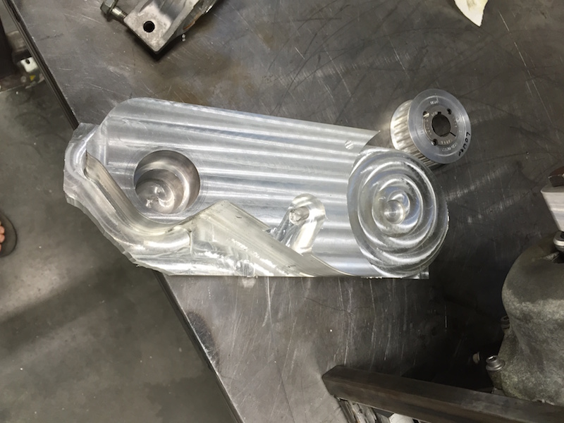
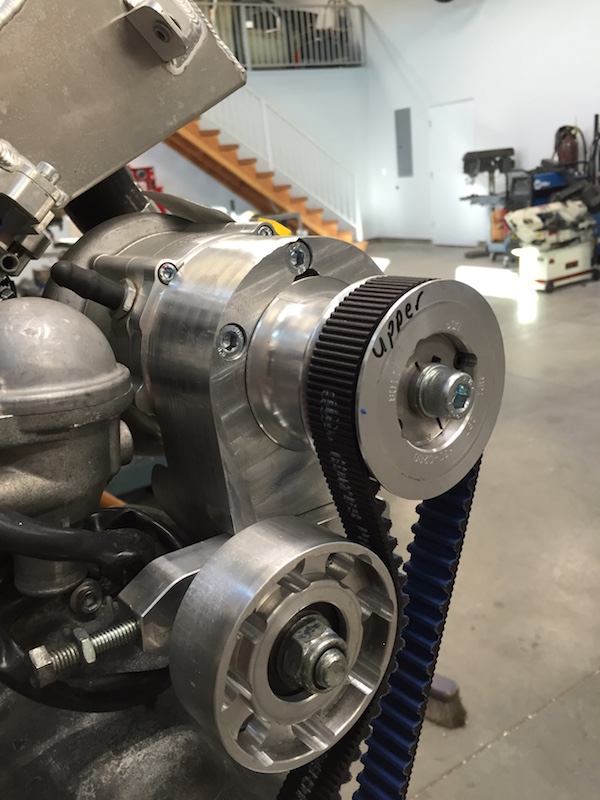
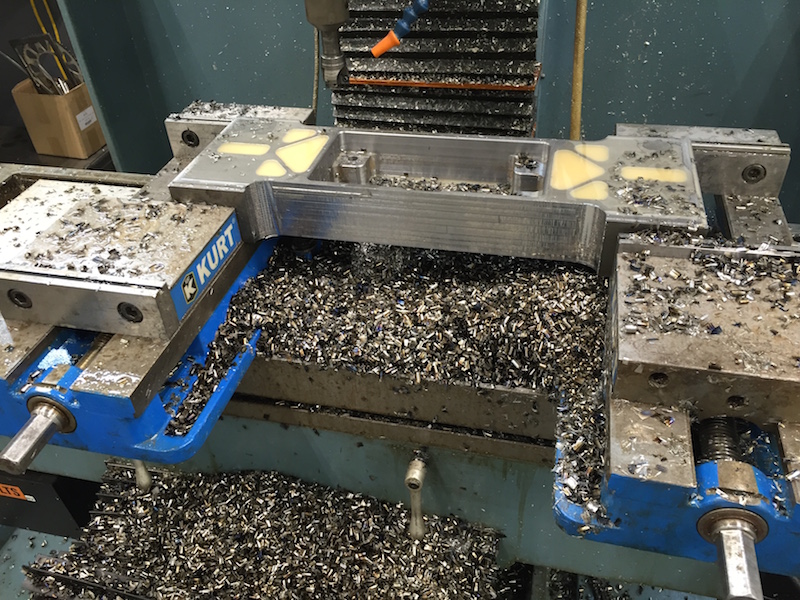
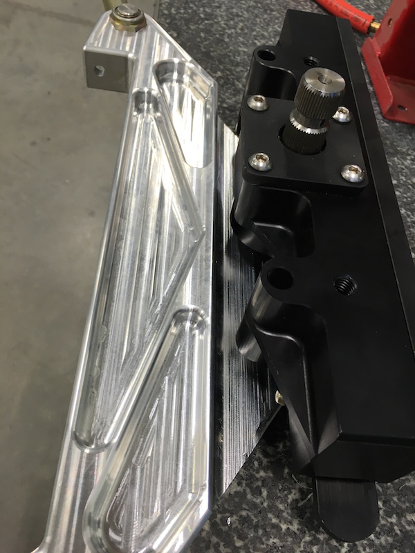
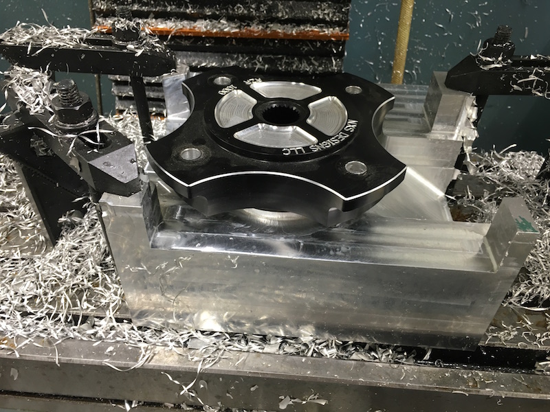
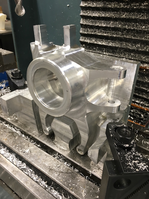
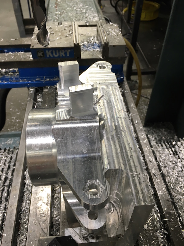
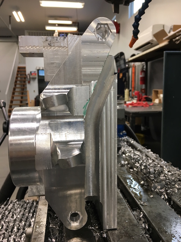
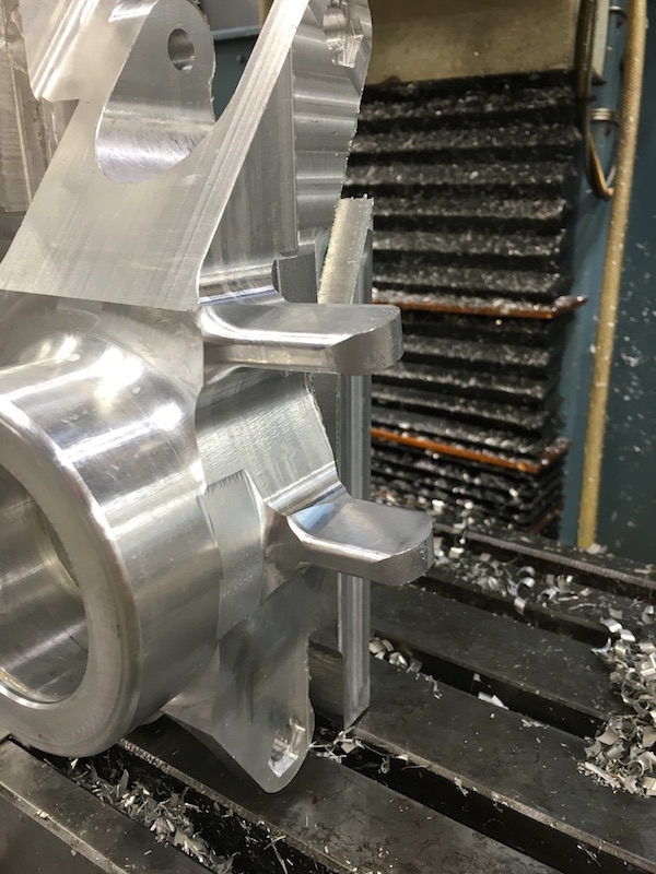
Spent the better part of the day making more chips and finishing the mount. I'm pretty happy with it.
There are a couple small things that still need to be done - gotta tap a hole, shim a spot and clean up the edges, as some of them are sharp.
Pulley goes here:
Still had a bunch of stuff to remove in this shot:
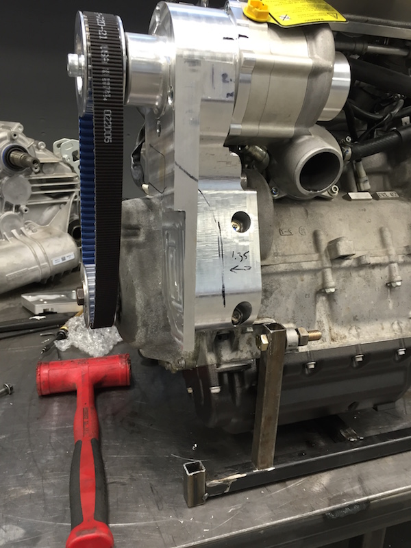
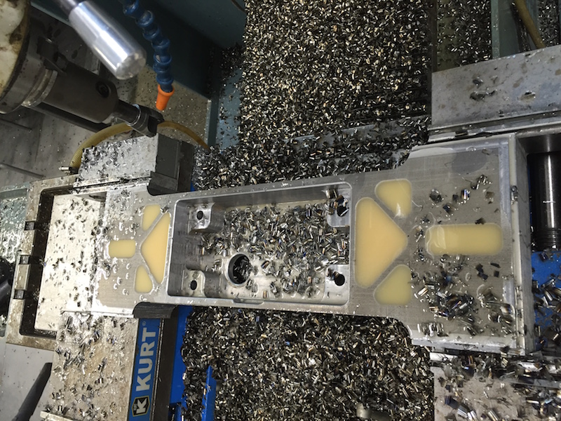
Finished mount:
 |
 |
||
 |
 |
 |
 |
clutch spacer/alignment jig:
Mar 11, 2016
I've actually been able to get stuff done. Between the gathering and having guests on and off since November (come on hot weather - people don't come out...) my shop time's been short. This week's been pretty free and next week is too, so time to make stuff.
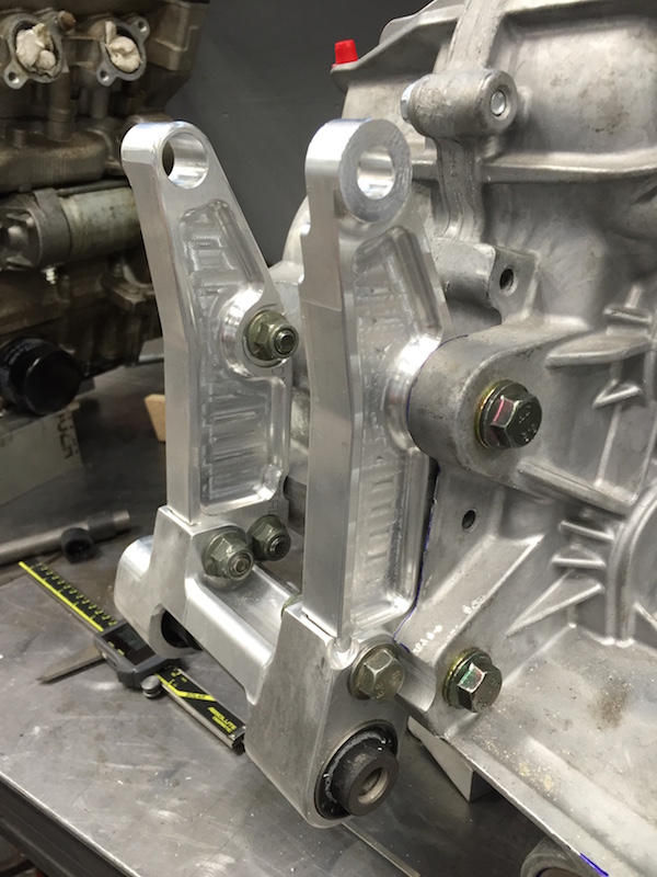
Originally I was planning on attaching the trans to the engine and having one packaged piece but I've come to realize that there's no place on the bottom of the engine to attach the bottom of the trans to. There are two little ears that stick out and have recesses under them, but they're widely spread and I don't really think they'd be the best thing to put 200+ hp pulling on.
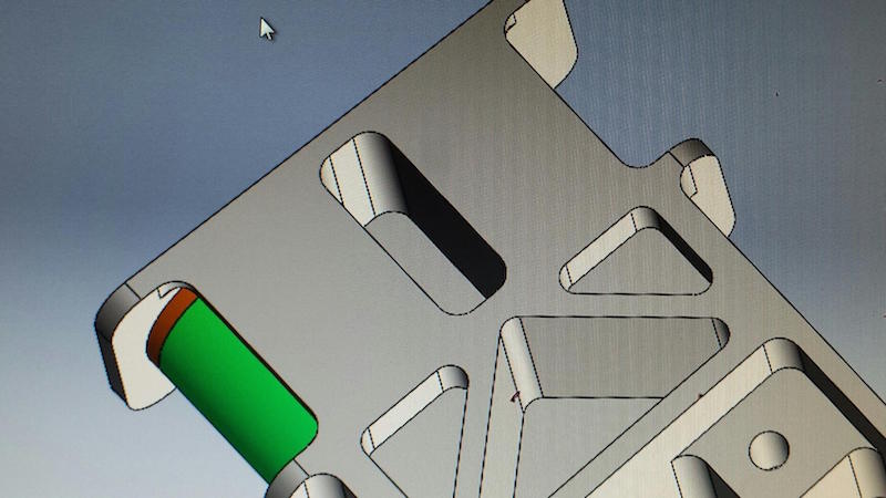
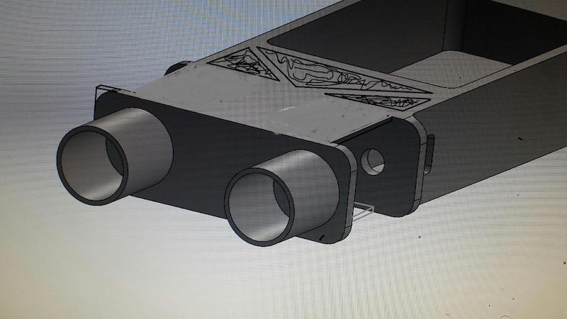
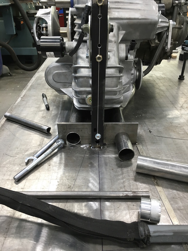
Here's the plate idea that I started out with. The two trans mount uprights bolted onto the plate and the plate was going to reach to the tabs and have pins that would have fit into the recesses.
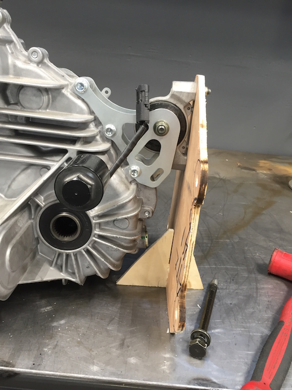
Then I started thinking I should just mount the bottom of the trans into the cradle that will hold it and the engine so I rethought the lower part of the mount.
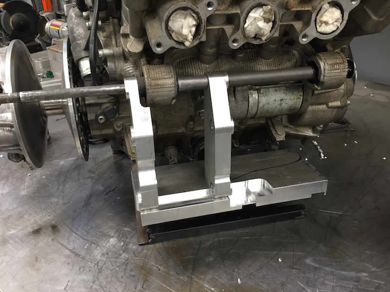
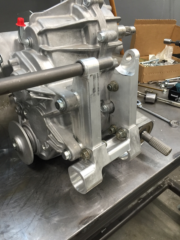
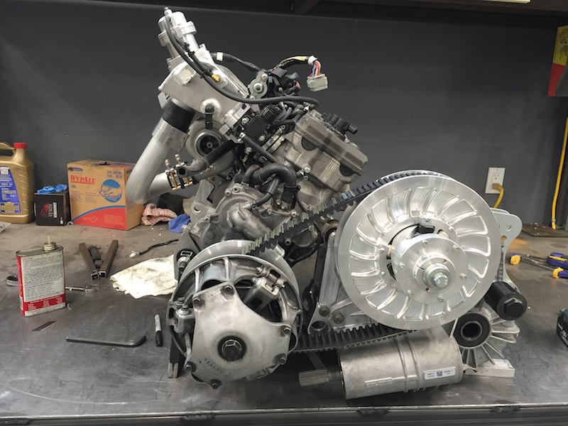
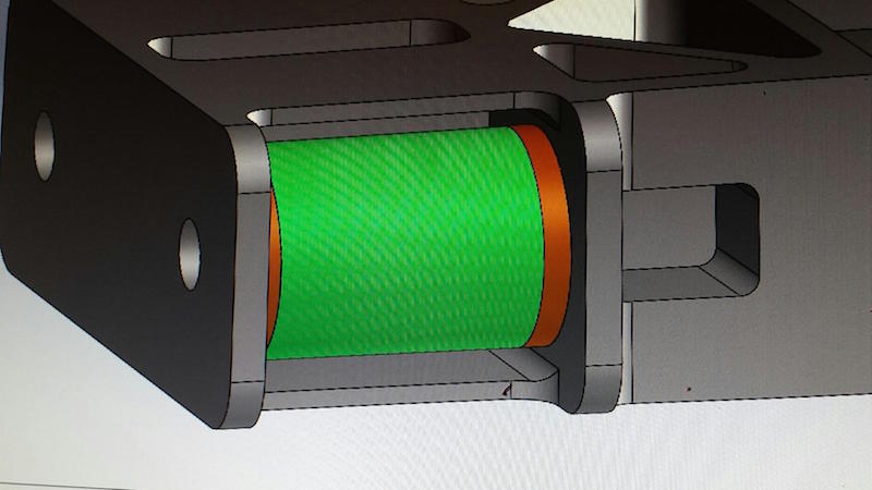
Now it's a bridge between the bottom of the two uprights (they were going to be bridged before this idea) and it use two of the rubber isolators out of the engine mounts. This will let me keep everything nice and aligned and able to handle the hp.

The uprights fit down into two pockets very snugly.
 |
 |
 |
 |
The trans/engine mount in place:
 |
 |
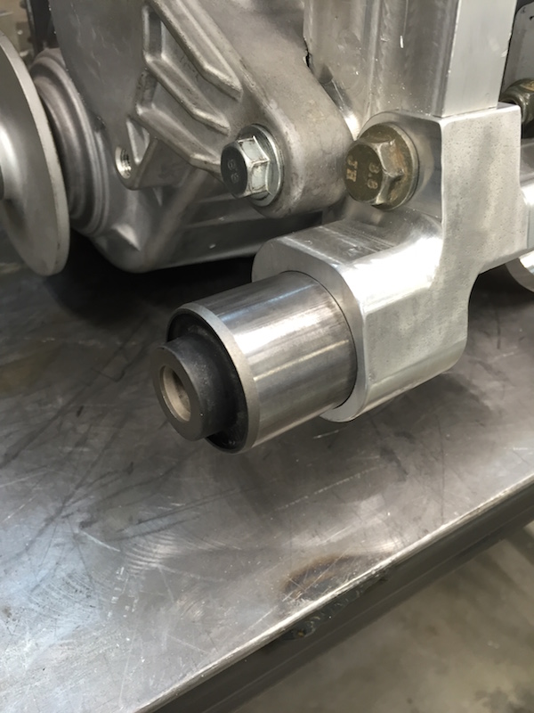
The isolators get pressed into the big holes:
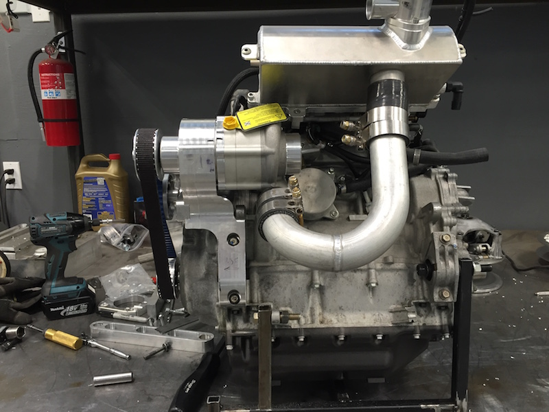
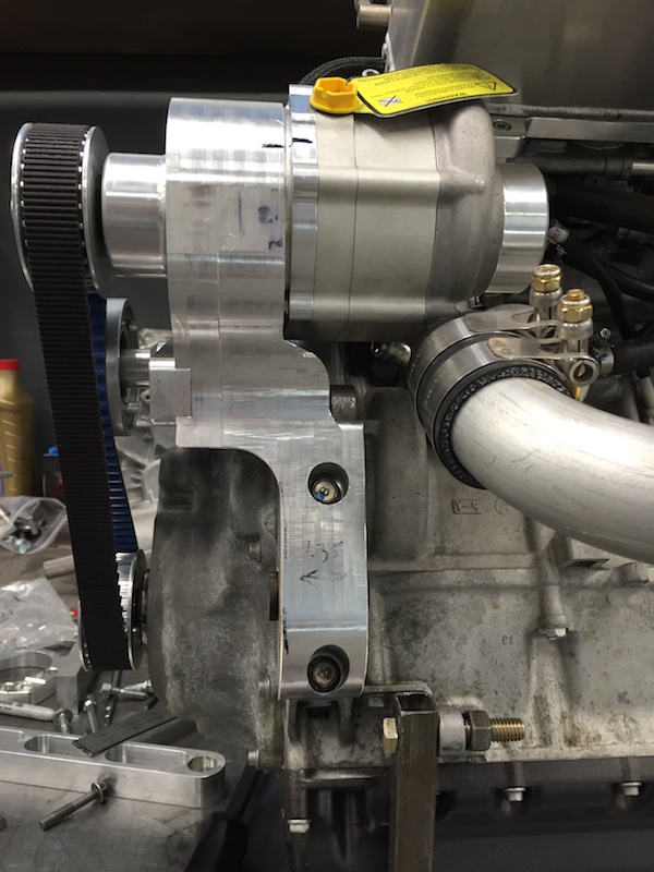
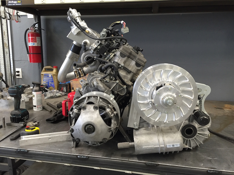
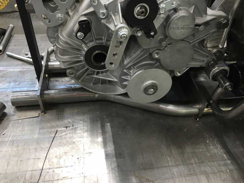
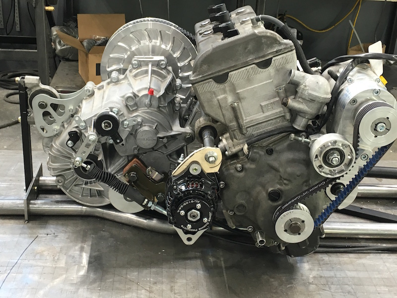
The power plant w/o belt and secondary:
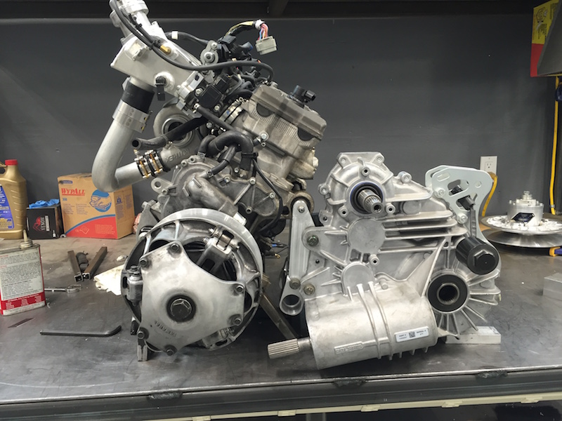
And with belt and secondary:
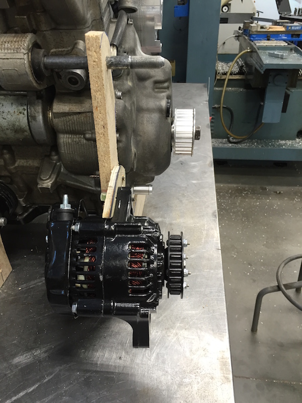
I started looking at the alternator mount again. I think it's going to get mounted to the cradle and not to the engine. There's just no place to hang it from unless I make another monstrosity like the supercharger mount. It'll be a lot easier to put it elsewhere. I'm still planning on driving it off the end of the crank and I'll have the pull as close to 180 degrees out from the pull of the supercharger. Should lessen the load a little bit. If the idler wheel had enough traction, I'd try taking it off of there, but I'm afraid it's gonna slip.
Mar 22, 2016
We have a front lower bulkhead!
Flyer and JD66 have been pounding away at it in SolidWorks and ACAD. I'll be making a bunch of chips here soon.
The piece of billet will start out around 65 lbs and end up at 18.8. I'm waiting on end mills and have to go to the metal supply house.
Random shots, one just for Flyer:
 |
 |
||
 |
 |
||
 |
 |

 |
 |
These pieces are flimsy 1/4" ply. Next set (no pix, still being figured out) are 1/2 MDF, then drawings, laser and plate.
End mills arrived, now I have to go get a big ass chunk o'steel.
Apr 1, 2016
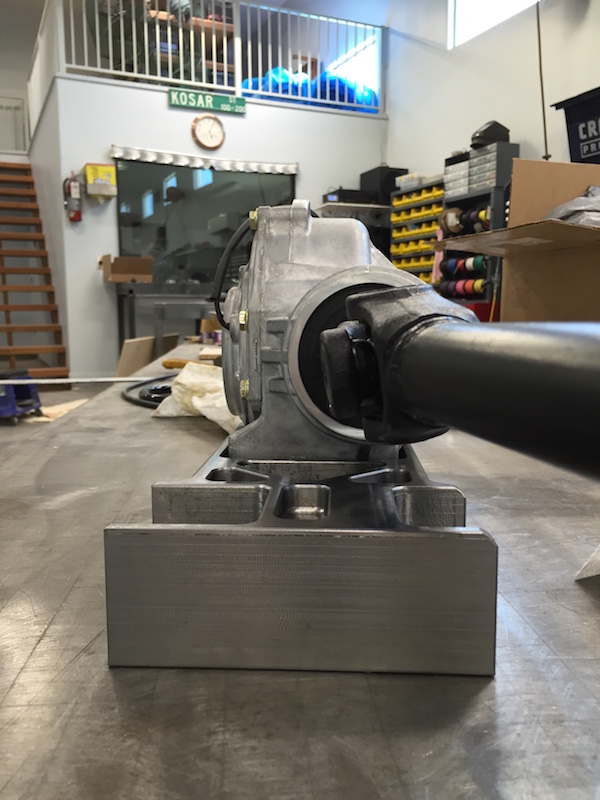
So as I start working on the engine/trans cradle, I discover that there's not enough clearance between the exhaust header and the top of the trans. Been there, done that with the Briggs.
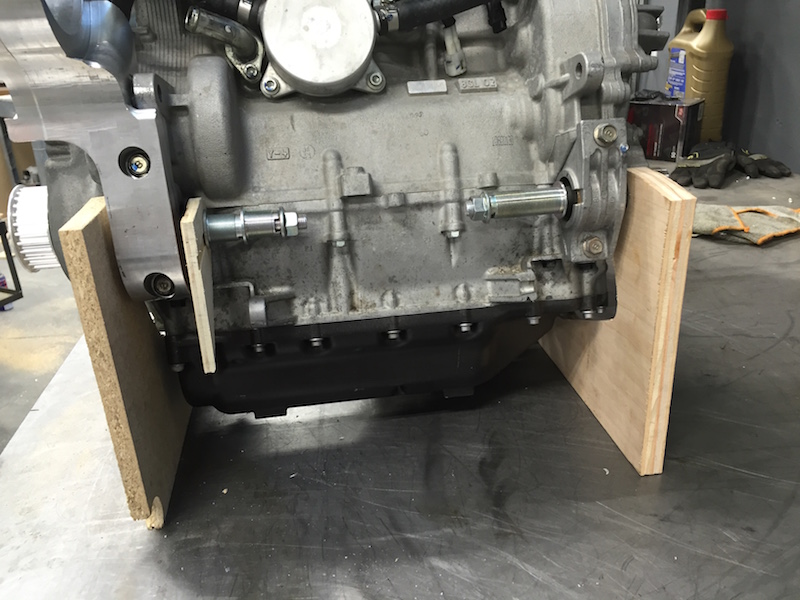
I had 2" stock when I did the first mounts and really needed wider stuff. 2.75" works perfectly. I was able to lower and move back the trans by roughly 1/2" and it gave me all the room I needed.
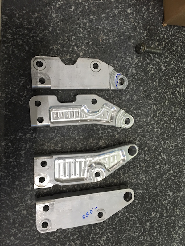
New mounting arms compared to the old ones. New ones are a lot nicer looking...

Now that I have better clearance, it's changed the angle of the engine, which means new cradle pieces:

Was able to get spacing for the side pieces in relation to the mounts dialed in also. The spacers will probably get integrated into the cradle when it all happens.
The rear trans mount will also be the rear suspension bulkhead (I think. Could change)

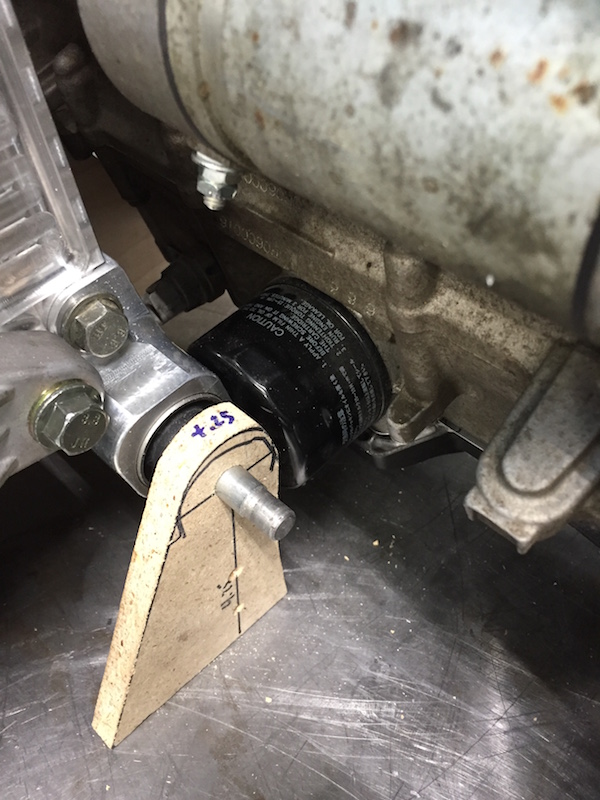
Looks like I'll need to make a filter relocation piece - I'm good with that - can put the filter in easy access.
There will have to be some cross bracing for the lower mounts - that will come a bit later, though.
Supercharger side of things - not quite sure how this one's going to work out yet. The alternator's going to get hanged in there somewhere.
It's pulley will line up with a drive pulley that will be mated on the outside of the s/c's pulley. There's enough support on the end of the drive shaft.
Front of the cradle will have boxed areas for the mounts and there will be a cross brace that holds everything in place.
The plan is to be able to drop the entire drivetrain in place, cradle and all. Flyer's trying to get me to do one BIG ASS plug that will allow the entire wire harness to be disconnected in one shot. We'll see. I know there are plugs out there like that.
Waiting on a large chunk of steel to show and it'll be front lower clip bulkhead machining time.
Apr 19, 2016
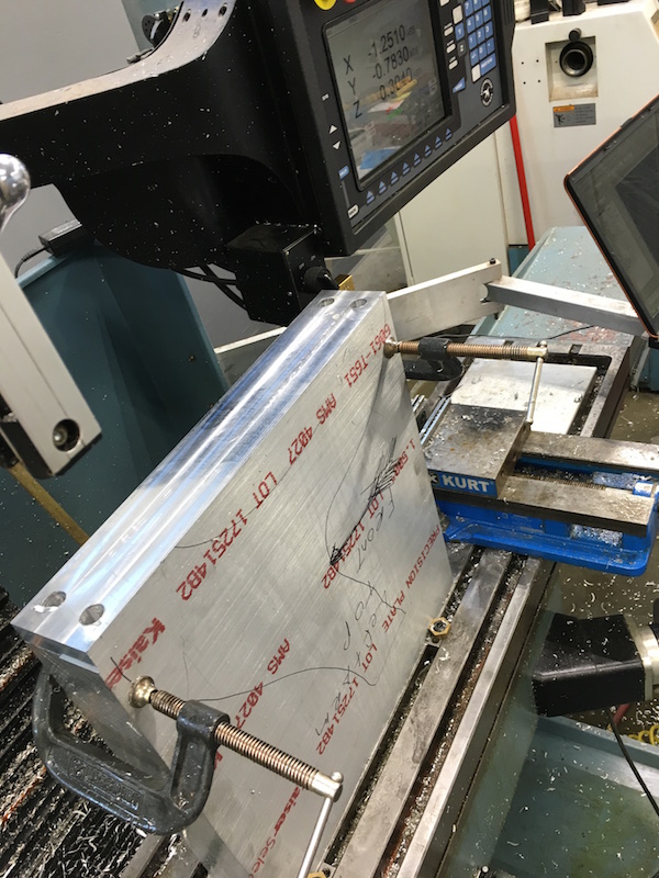
A sixty eight pound chunk of steel arrived about two weeks ago, then we went on vacation for a week.
I'm back at it now (and we'll have no more guests/visitors/side tracking/crashing people from MBN).
According to JD66, the end piece will be about eighteen lbs. when finished. We'll see.
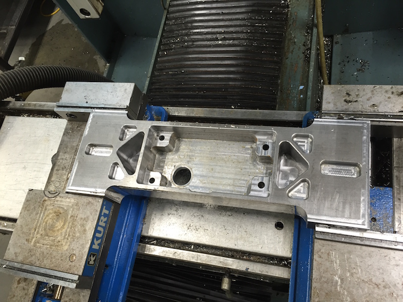
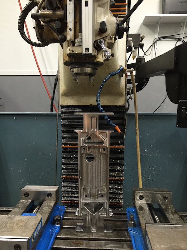
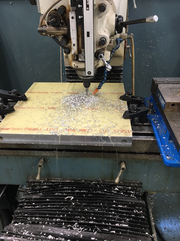
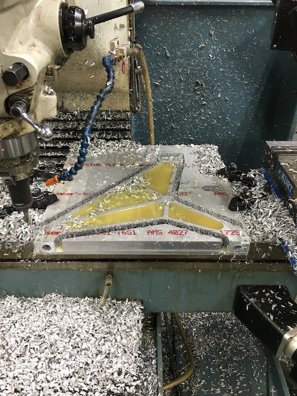
Chucked up and ready to start making chips:
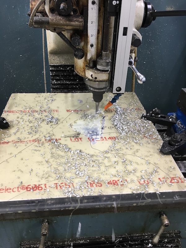
First couple of pockets:
I managed to kill three end mills yesterday. One was my fault - tried to go a bit deeper than the bit was capable of and rubbed the noncutting part against the side of the material in the big triangular hole. 92 bucks literally down the hole... I know better than that. It was a shouldered cutter - I was trying to make nice round corners at the bottom of the holes.
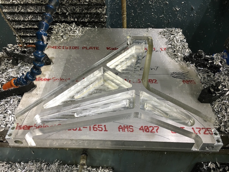
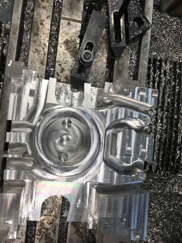
Main body pocket where the diff sits - It's unfinished presently because I killed two more end mills while working on it - both of them bound up in the chips while cutting. I wasn't paying attention to the second one, so I'll take responsibility for that. Third one was the same thing, but I thought I was keeping up with chip removal. Guess not. Ended up being a really expensive day. Damn. New cutters are on the way.

I was able to go ahead and get the diff mounting holes and drain hole cut into the piece.
I still need to finish hogging out the bottom 3/8" of material once the cutters show up and then work on the rest of the piece. I'll be really careful about binding too.
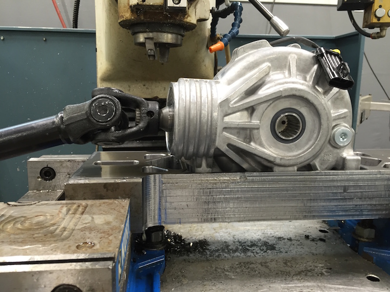
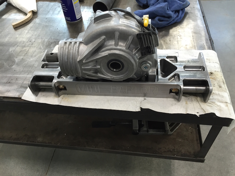
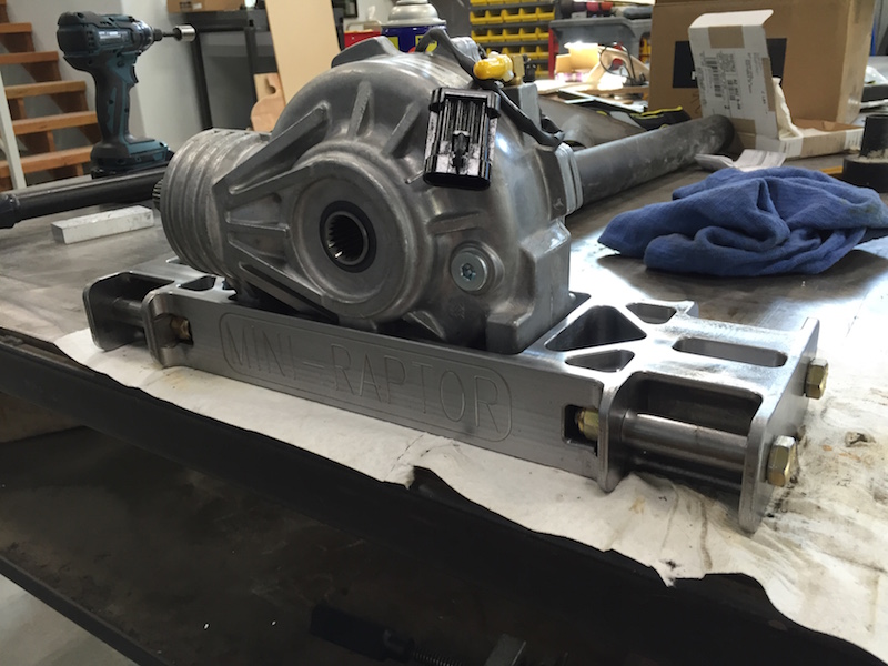
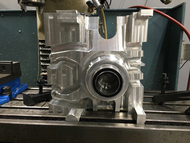
Diff in place:

There's been LOTS of chips and I'm keeping busy with the vacuum while it's all going down. Vacuum's getting heavier, bulkhead's getting lighter. More to come.
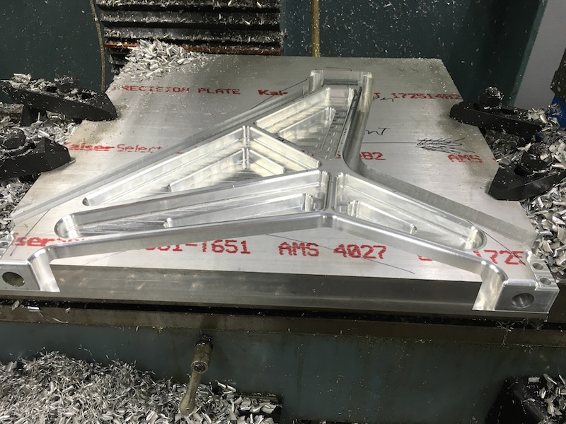
Mainly did roughing, but I did get the main body pocket finished out.
Lots of chips. Lots of HOT chips... I danced a bunch today.
All cleaned up. I still need to finish cut the sides and the pockets for the suspension mounts.
We were worried about clearance for the u-joint. It's not going to be a problem at all.
I'll get my new tooling tomorrow, I hope, and finish out the sides. Then it's pull it out, relocate it and do the pockets for the suspension mounting points.
I have to drill four .5" holes in the ends - not sure how I'm going to hold the thing or if I have enough clearance. That is going to be interesting.
Apr 22, 2016
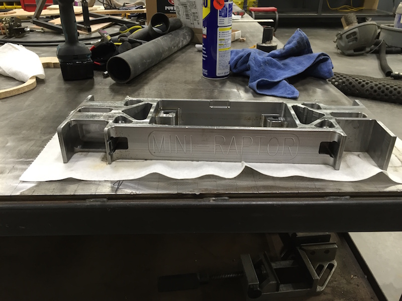
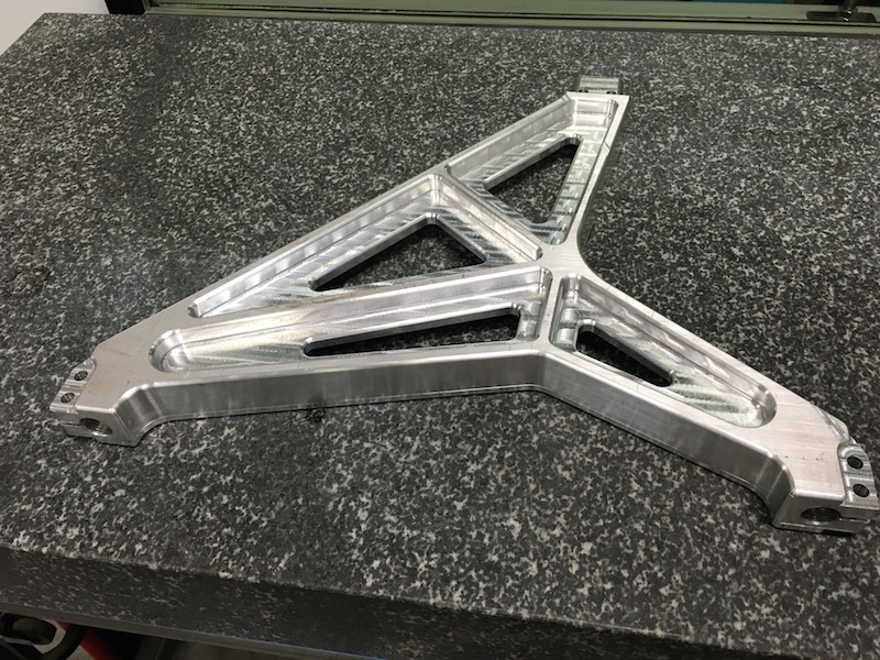
It's off the mill - machining part 1 is done:
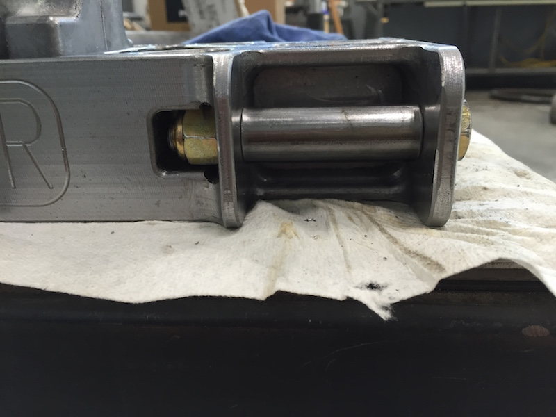
A little detail shot:
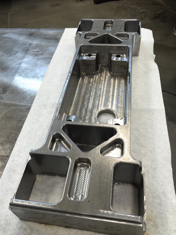
It's gone from grunting and working to get it onto the mill to being able to pick it up with one hand. It's probably a little over 20 lbs from the original 68.
I have to keep the darned thing covered in WD40 - the rust, even here in less than 30% humidity, is quick to set in.
Next will be the sides - cutting out the webbing on the outside of the pockets, holes for the nut capturing, and some other detail stuff.
Apr 24, 2016
I still have to radius a couple small corners, but it's pretty much done other than the four bolt holes that will get put into the ends.
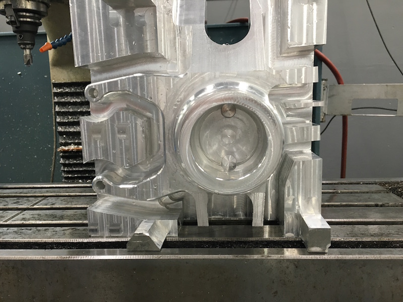
View of the diff and drive shaft. (Flyer's been asking for this shot):

She's almost done - side shot:
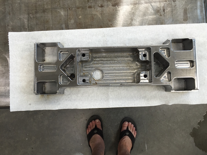
Bottom view:
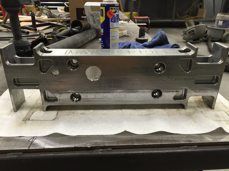
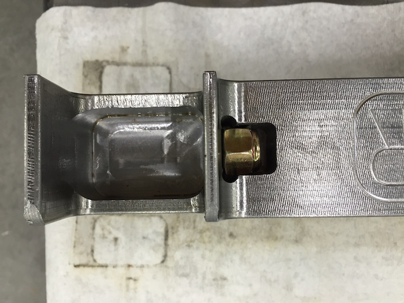
Pocket detail - small pocket is a nut pocket that holds the nuts where they need to be.
It's gonna be tight, but I'll be able to get the .500" drill into a collet chuck (low profile) and drill the holes for the lower suspension mounts.
Apr 26, 2016
More progress - the lower bulkhead is done now. I finished radius cutting the corners and doing some little attn. to detail stuff.
Got the spacers for the lower a-arm pivots cut too.
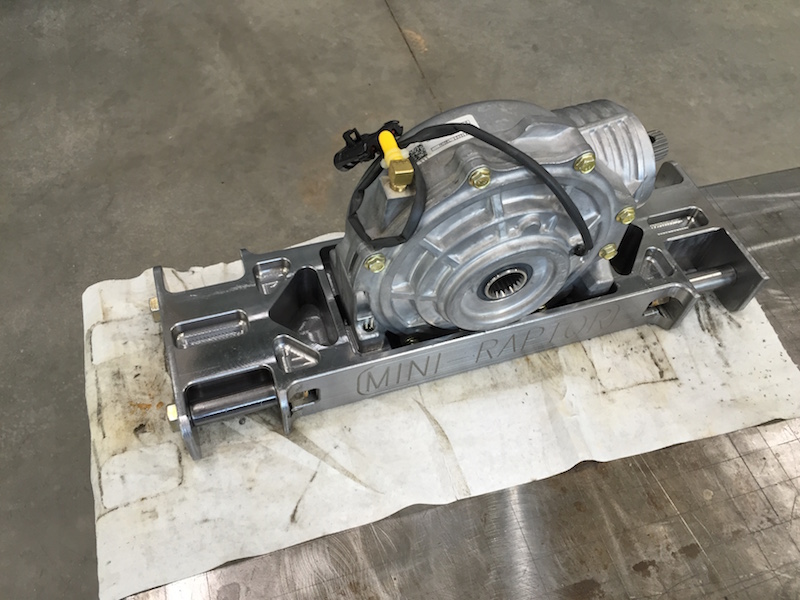
Jun 24, 2016
Justin:
We have been making some progress behind the scenes, CAD design is coming along. And with the temps soaring in Phoenix, K-Fab will likely be machining away in his air conditioned shop.
Flyer and I have been focused on the front bulkhead design. Certainly a lot to squeeze in there with 4WD, but it will all fit. The bulkhead will tie to the front bumper, but we've decided to wait on placement of the front bumper until we can mock everything up in the shop. The CAD for the front clip is only so accurate. Moving onto a-arm design next - the upper will be billet aluminum, the lower boxed plate.
K-Fab is working on the spindle design - another billet piece. We should have some machining/laser cutting progress to report before too long!


Aug 16, 2016
From Justin:
Lower arm design getting close. Flyer pushed for the more complicated route - more time invested but it's looking pretty killer.


Aug 17, 2016
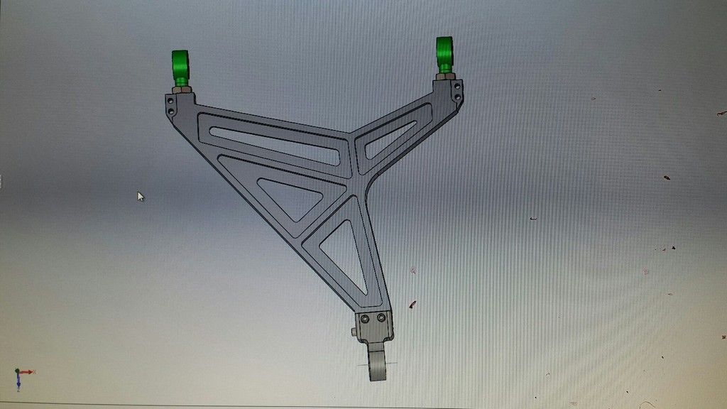
From Flyer:
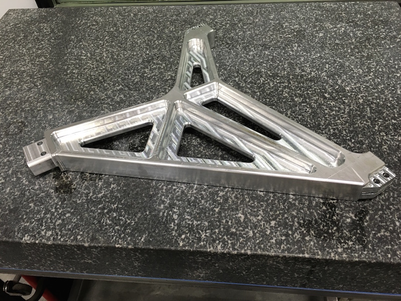
Here's the upper arm. There are still a few small changes to make that will lighten it up even more and provide better triangulation at the heims.
A Minibuggy member, Lance-W, chimed in:
Lance-W is quite the accomplished engineer - like he makes rockets accomplished...
Can I make a suggestion? When you tab it with the top and bottom sheet. Make the holes in the top and bottom sheet log and the tabs on the verticals long. You get a way better weld on the last sheet you put on (the one that closes out the box). Otherwise it's closed out and you only get a little short weld where the tab comes thru. Ask me how I know this..........It was quite the "what a dumbshit I am moment" for me when I realized what I had done or hadn't done depending on how you look at it. You did what I am talking about on the one long inner rib just not on the other ones.
To which Flyer responded:
Hey Lance! That long center slot has been changed to a smaller castle design. Everything is being designed to allow for complete internal welding. It's a work in progress and a few slots (the rib behind the shock pocket for example) need to be changed. The outer side plates go on last so a huge portion of the internal welding can be welded from the side similar to how my arms were welded. The large slots are for the areas we can't get to from the sides. Most of the internals will be mig welded. Here's a pic of one of mine showing how everything was welded internally from the side.

Aug 25, 2016
From Justin:
I know you guys want to see metal parts... and soon you will... but for now, the lower arm design is finished. Moving back to the billet aluminum parts to finalize the steering geometry and K will be making chips.
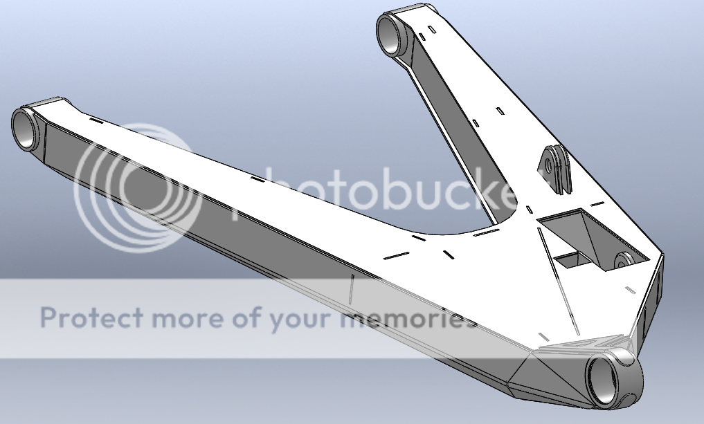

We added the nut pocket, a drain for the shock pocket, interlocking features where needed, and a tab for the limit strap. Weight for the lower arm is 14.4lbs, not too bad for a 27" long arm!
Oct 1, 2016
From Justin:
Working on the lower arm weld fixture. A lot going on here.

Oct 14, 2016
Almost finished the spacers and jig parts. I still have three or four pieces to go:
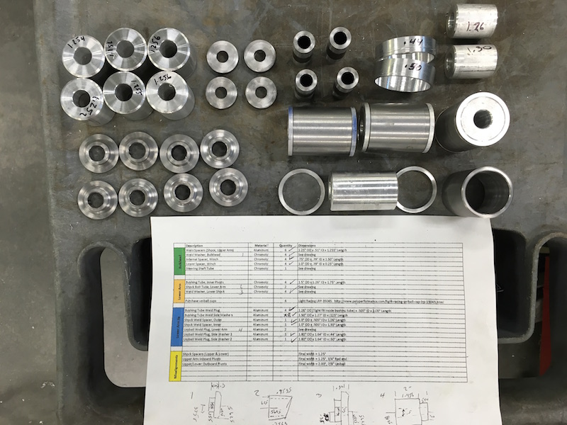

The upper a-arm material may be here today, the uni-ball adapter material is here and I think I've figure out how to make it - it's simple but there are some angles that a non-fully 3D mill will have issues with. Hopefully I'll get some time either today or this weekend to see if I'm right.
Yes, there's finally stuff happening again! - my better half's cancer issue looks like it had it's ass KICKED TO THE CURB! Not even a sign of scarring in the last exam. WOO HOO!!!
And one last shout out to my 525 Industries tube prep tool. Flyer and TALON have been testing it out also and hopefully are enjoying it as much as I am. The designer should be pleased to hear this.
Eh Bull?
Oct 17, 2016
Hey Bull - I need measurements off the rear suspension of one of those Briggs cars. I know how well they work and I think I want to adapt it to the Mini-Raptor.
------
Design a bunch
Order wrong sized stuff
Do things incorrectly
Start again!
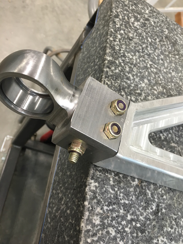
Got my piece of 7075 for the spreader bar. Somehow I totally screwed up and didn't realize it was a 6.75" wide piece of aluminum was needed, not 6" wide. JD66 is working on seeing if I can make this piece work. We need to relocate the support rod upwards just .375" and I can use my now useless piece of 6" stuff. Otherwise I'll have a nice large chunk of 7075 sitting on my shelf. Crap.
Measure thrice, cut once, use the tube stretcher, or just realize that YOU'RE DOING IT WRONG...
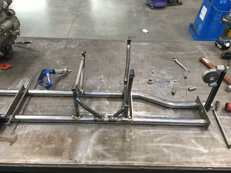
When I started out working on the power plant mounting system, I built from the mounting bungs down to the table. It works well, but it's a really crappy way to try to locate the lower frame tubes. The farther I got into this the worse it got. So last night it was start over time. I've removed all the tacked down in the wrong spot tubing off my build table and started again, this time making and using jigs so everything is done right. Flyer and JD have both designed and worked around the concept of using jigs for builds. I was sort of stubbornly ignoring it (more work, more material mentality, which is STUPID...) I now have jigging welded to my build table and things will be straight and correct.
Pix a bit later of the right way to do this stuff. I've been doing this long enough - I should know better. DOH.
Oct 18, 2016
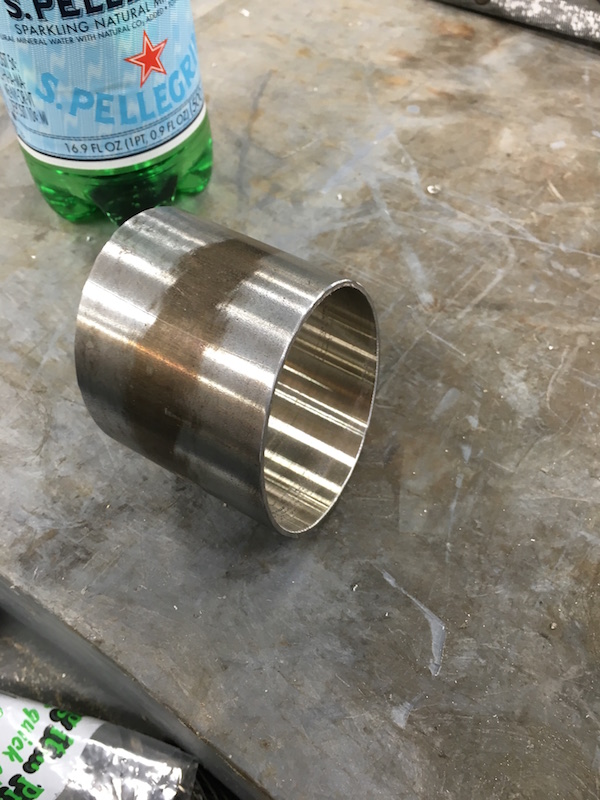
Of the machined parts I still had to do the front bulkhead through tube. Fortunately I had enough 2.5" for the uni-ball adapters to make the piece.
Bored it out - what a pain! Removed 2.375" x 2.6 just to make a tube.


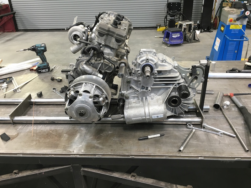
Redoing all the mounts:
I'm using 1.5x.062 mild for mock up. It'll become chromoly and probably .120 wall for the actual chassis
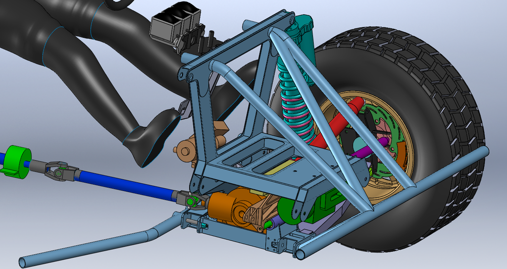
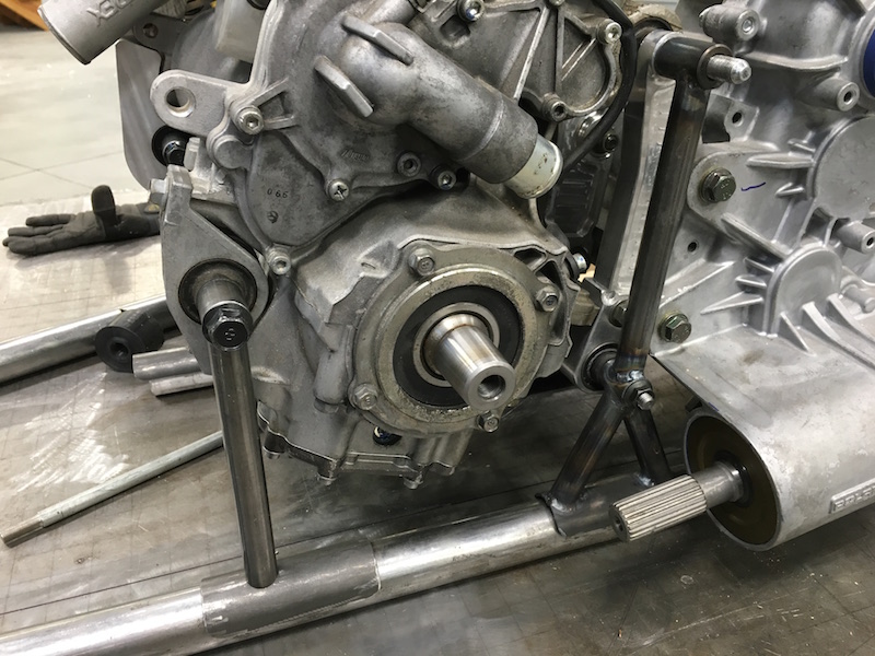
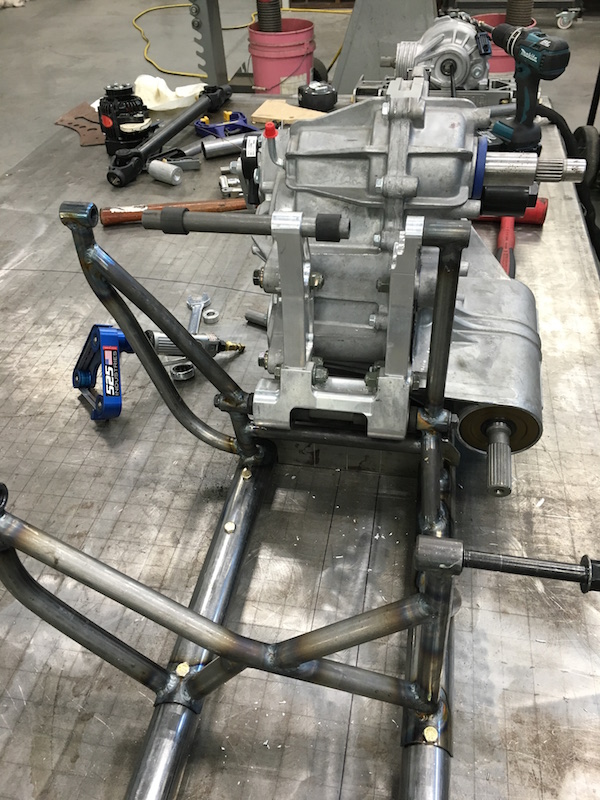
Trans and engine set up in the right spot:
You can see the jig locators on the frame rails here:

Trans locating - everything is set up on the grid on my table:
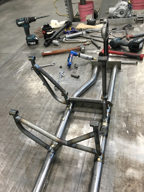
Front lower transverse link is going to have to get tucked under the PTO and parking brakes.
The bent tube under the trans on the brake side will get modded - either move the bend forward or stub into a horizontal tube farther forward between the rails.

The engine cradle's complete other than a few more holes to bolt it to the frame rails. I'll make an internal nut and a clamp that sandwiches the cradle's half tubes.

A-arms arrived:
Oct 23, 2016
I had just enough room in Z. Whew.
This part was a little scary - it's a long piece held with little area and way down low. I took teeny tiny passes to square up and face the edge I based everything off.
Four holes for 3/4" heims.
And the chips begin:
I think I see an a-arm coming out:
This side's done - all the radius edge work is done, the pockets are cut deeply enough that I won't have to do them on the other side.
The arms are mirror images, so it's two programs, this one and then flip and modify a bit.
I'll still have to figure out how to cut the slots that allow pinching of the heims, but that's not going to be too terribly hard but I see broken 1/8" endmills in my future.
Oct 24, 2016
The arms are done!
My mis-alignment when flipping the plates over ended up being about .002" - you can see the "seam" on the long face. I'm good with it.
The uniball adapters will fit over this nub:

The pinch clamps work well.
I still need to do a little clean up work on them - bevel a few edges, sand the top and bottom surfaces smooth - satin faces with machined inners will look pretty sweet when they're anodized. No clue on color yet, but they'll get it.
5/8" end mill doing the outer profile. There are chips EVERYWHERE.
Oct 27, 2016
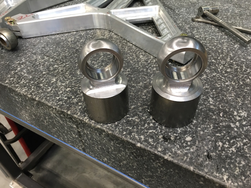
WTF is this? Super strong door knob?
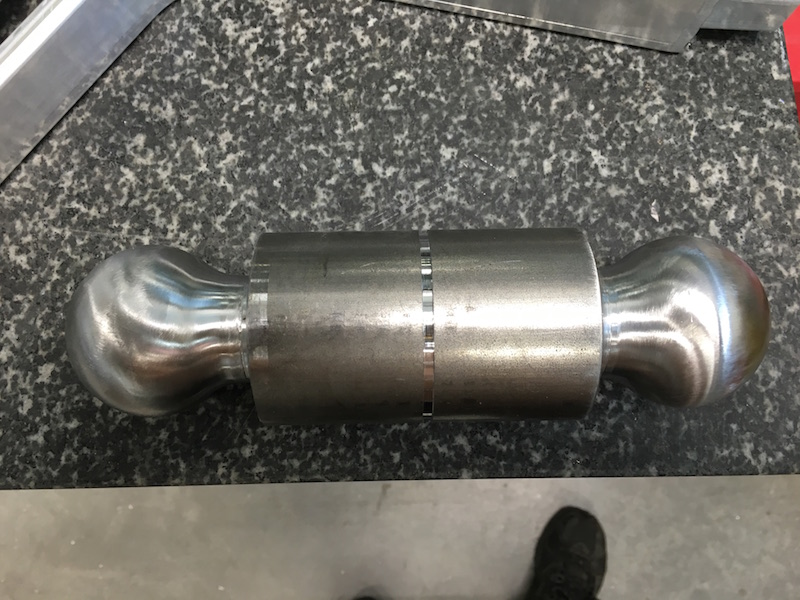
Oh! It's this!
This is the uniball adapters. I'll cut it into two parts and then machine the ends that slip over the nubs on the end of the a-arms.
Being that the uni-ball is clocked 5 degrees, I had to get creative on how to do that. Turns out it's easier to do the rounded parts first, on the lathe, then cut the pockets and retaining clip groove then go back and do the body profile and pocket. I'll be able to cut the pocket and then test fit the arms to make sure each piece fits perfectly.
These should be done today.
side note - there is a lot of conversation on these forums. Especially among the listed group at the beginning of this trek.
Bullnerd:
Wait a minute?
I thought you were machining all this stuff?
Who's shoes are they?
Me
LOL!!! Yeah, well... Those little chips are freaking hot! My socks suck - they have a bunch of nylon in them and now they have a bunch of tiny needles that have melted to the nylon in them. I've not been wearing a shirt, though. Have the spots on my arms and chest to prove it too.
Flyer
Haha! I recently saw a picture of K in pants AND shoes at the same time. I didn't recognize him for a minute!
Me
Where's TALON when I need back up?
bdkw1
The mighty have fallen........
He's getting domesticated.......
Me
I'm going to quote you here:

Maybe I'm good with it....
Found the right one.
She loves the dirt and the desert as much as I do.
bdkw1
Also, Nice doorknobs. Maximum strength with maximum clearance.
Me
I was expecting at least "What knockers" from you!
Thanks.
They should work well.
--------------------------------------
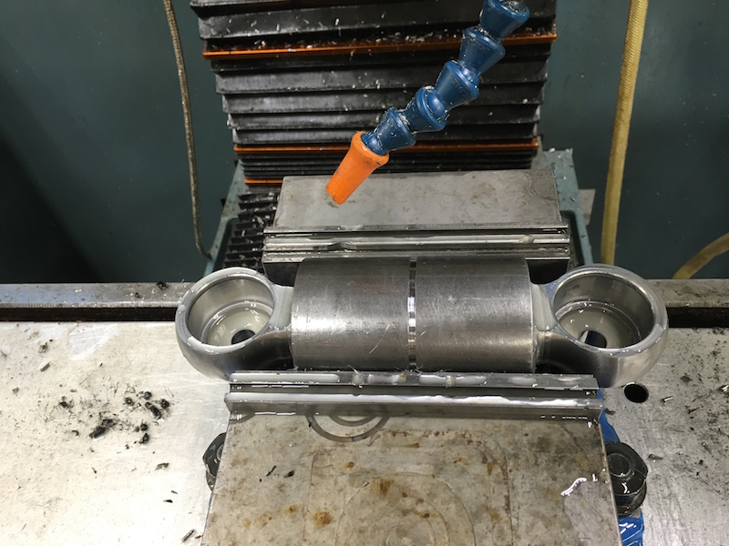
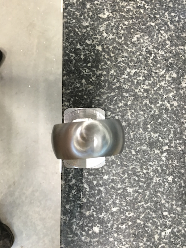
Parted the knockers:
Uniball holder clocked 5 degrees:
The pocket end. I messed up on the a-arm outer radius cut and used a .125 cutter. Should have used a .250. The smaller radius left an unblended area. I'll hand blend it later.
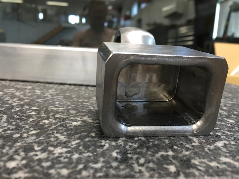
Adapter in place:
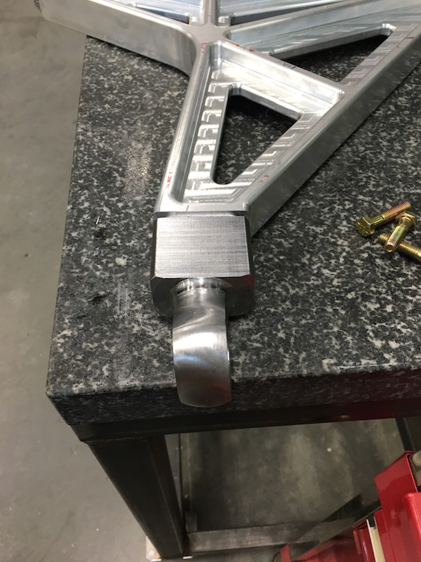
Nuuuuuuuut Pockets for every fastener:

Billet A-Arm Porn:

I'll get on the steering spreader as soon as the material arrives. I have a bunch of CAD work to do anyhow - need to finish the front spindle design.
It feels really good to get back into this!
Nov 11, 2016
My 7075 showed up.
Does anyone have a tiny forklift I can borrow?

Nov 3, 2016
More billet porn:
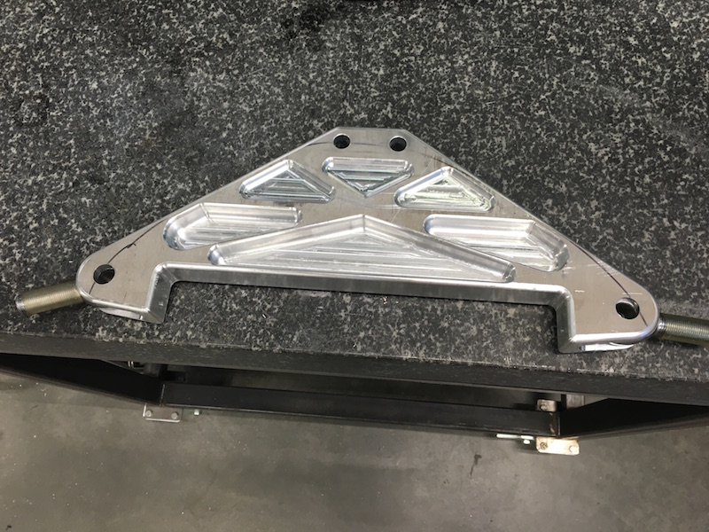
The steering spreader is about 3/4's the way finished. The front side is done, now I need to flip it, skim it down to 1.25" and finish out the back side pockets and clearance area.

Hopefully I'll get a chance to finish it today and then it's time to move onto the front spindles - and of course the billet for them is on "special order" status meaning I won't see it until next week.
Nov 5, 2016
Nice Rack! (spreader)

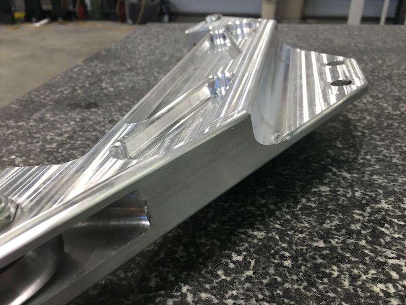
Still needs a couple of clean up things.
3.5 lbs w/hardware.
Nov 6, 2016
Flyer:
That sits under the rack. Since we wanted front steer and had to clear the diff, the rack had to be mounted pretty high and fairly far forward. The spreader moves the tie rod mounts below the rack. There is a rack/spreader support that mounts to the lower bulkhead with a cross shaft. You can see the bolt holes for the cross shaft by the heim joints.
The shape had to change quite a bit since we had to lower the tie rod for upper arm clearance.
Nov 12, 2016
Back to our regularly scheduled programming:
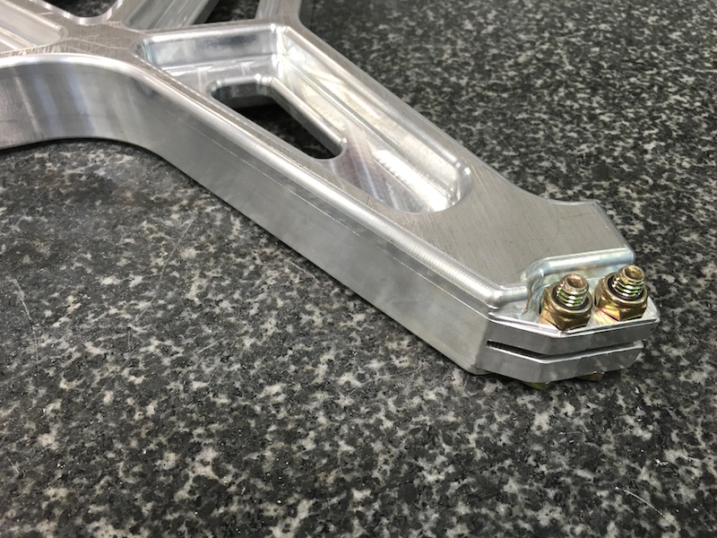
Finished the spreader. I'd managed to screw up on one particular cut and based the line on a blend line on the print instead of the correct line. That lead to .500" too much material under the rack. Fixed now:
I also cut the wrong size nut pockets, so that's fixed. Thinned out the two lock nuts also:

Somewhere in there is a front spindle. 54 lbs as it sits:

Chip should start flying in the next day or so.
Dec 3, 2016
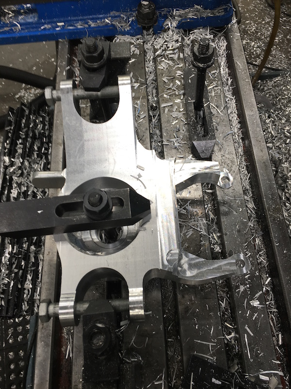
Chips are happening.
This is design on the fly - I have all the pertinent points drawn up in ACAD and now am trying to figure out how to leave them where they're supposed to be in the material.
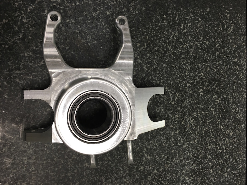
Main wheel bearing fits in the snout and the hub fits over it:
Caliper mount and upper a-arm mounts getting cut away:
There's a lot more work left and then I'll go back and radius cut the edges and meeting corners.
More to come shortly - I think this week is fairly open for shop time.
Dec 8, 2016
I actually got to stand in front of the mill today and make progress. Call it writer's block or something, but I couldn't for the life of me see the end product in my head. I have it on ACAD, sort of, but the finished piece was still sort of up in the air. Stood and looked at it for a little bit this afternoon and it started coming out for me, visually.
The darned Proto-Trak that I use is being pesky. I'm doing angled cuts in the X-Z axis and it doesn't want to offset the tool correctly. You'd think a center offset would be simple, right? I can't figure out where in the world it's coming up with its offsets, so I'm having to move through each pass w/o the tool in the mill and plot the points it's deciding to use back into ACAD and compare that to the correct path. Then it's offset/copy the incorrect positioned move (which has what should be the right coordinates) to the correct place.
It's a pain in the ass... I'm getting faster at it, though.
95% of the time the Proto-Trak line of stuff works just like it's supposed to but there are these fun little idiosyncrasies that pop out every now and then and they'll drive you NUTS! (kinda like a steering wheel in your pants...)
Anyhow, progress:
Upper a-arm mounts in here. This section's going to get modified a bit tomorrow.
Lower one mounts in here.
It's starting to look like something now.
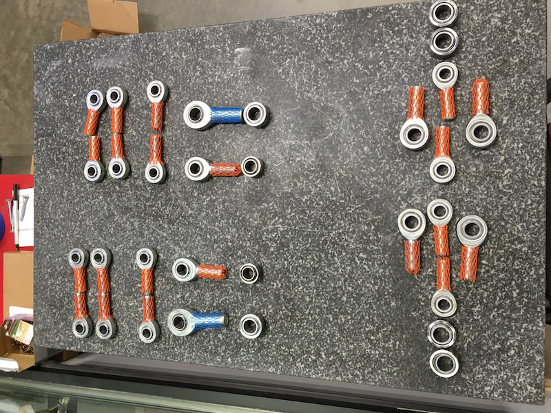
Got all my hardware a couple of weeks ago. All pivot points are covered.
Left to right:
Left group:
Transverse link pivots
Lower and Upper trailing arm pivots
Right group:
Upper a-arm rear pivots
Tie rod ends and spindle uni-balls
Upper a-arm front pivots
Dec 9, 2016
29 lbs.
Dec 13, 2016
24 lbs now.
Dec 15, 2016
22 lbs.
The steering ears are cut out now - man, that was a bitch. I went the wrong way completely doing these, but it worked. I should have made them larger, I think.
The rest shouldn't take that long.
Dec 18, 2016
Found a friend by the sink. Took it outside: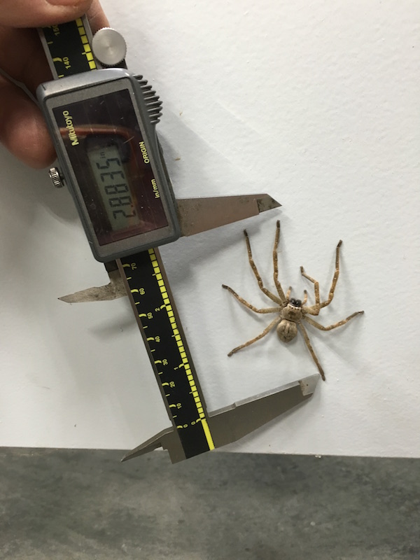
To make sure I got everything right and all the clearances correct I made mock ups of the hub, bearing and axle and made sure it was perfectly flush with the end of the snout so nothing could move. It worked well.

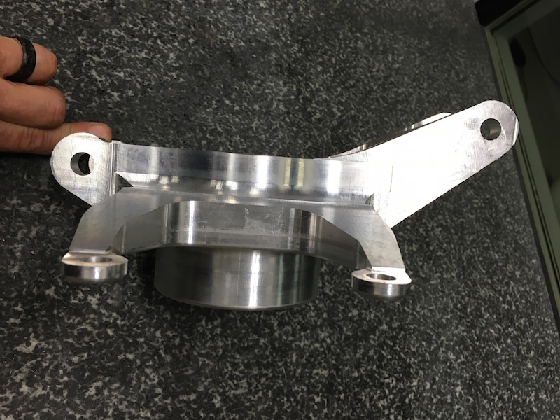
A little profile work:
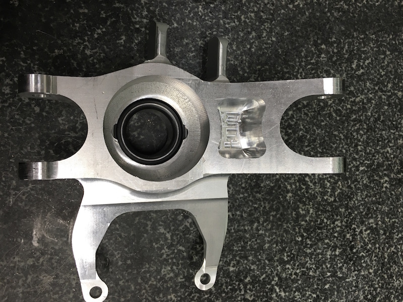
Back side without the brake caliper ears exposed yet:

Ears have been found and they were where they were supposed to be!
99% done!
I still have to drill the steering tab bolt holes and do some clearance/clean up stuff. I may have to open the inside of the bore in the back up a bit for boot/boot band clearance and I'll have to make special bolts to mount the calipers.
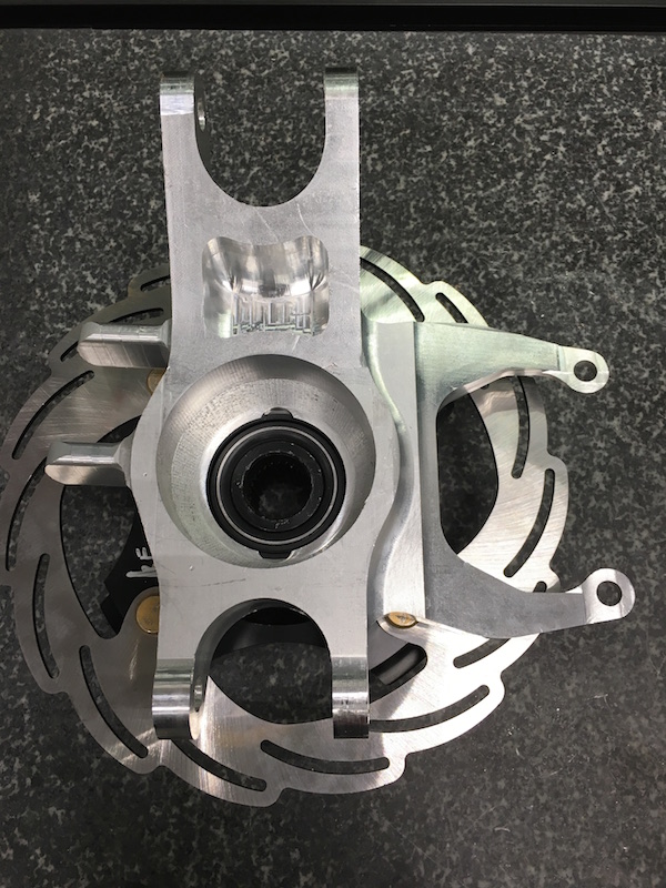
The carrier weighs 5 lbs from a 54 lb block of 6061.
With bearing, hub, rotor, caliper and all the hardware it's 14 lbs.
This is the left hub in the right carrier - rotor pattern's backwards. I figured I should point that out before Bullnerd says something.
The next one will go faster - I hope.
This concludes the building that happened up through the end of 2016. Click on the link below to be taken to what happens in 2017.