


The Mini-Raptor Build 2019
|
2016 build 2017 build 2018 build 2019 build 2020 build 2021 build 2022 build 2023 build 2024 build 2025 build |
 |
 |
 |
 |
Jan 5, 2019
Have had guests the past week, along with all the holiday stuff. Everyone left yesterday and I spent the day in the shop.
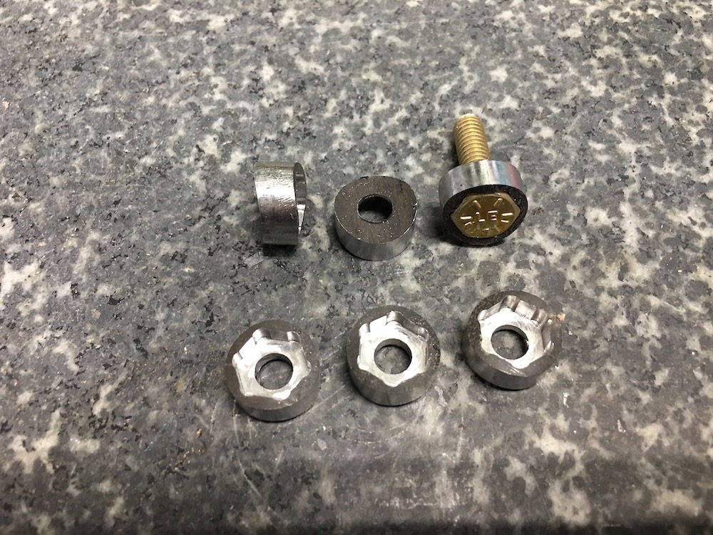
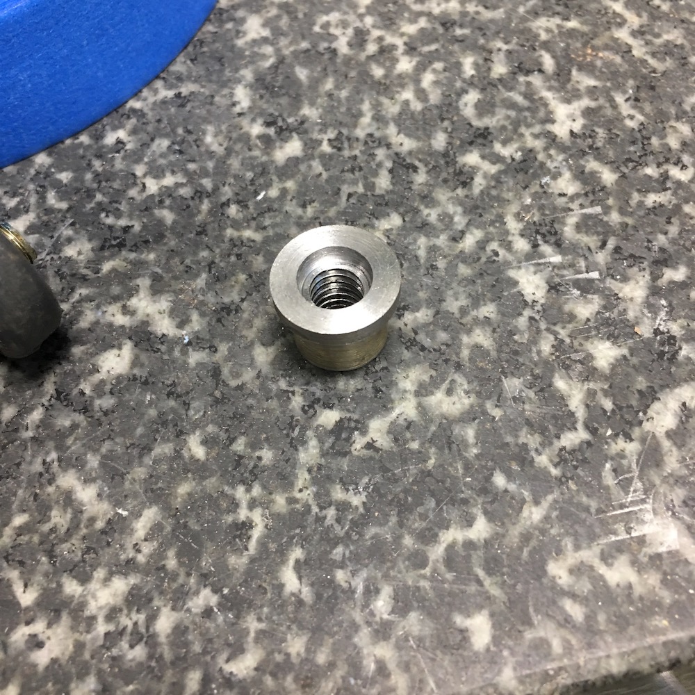
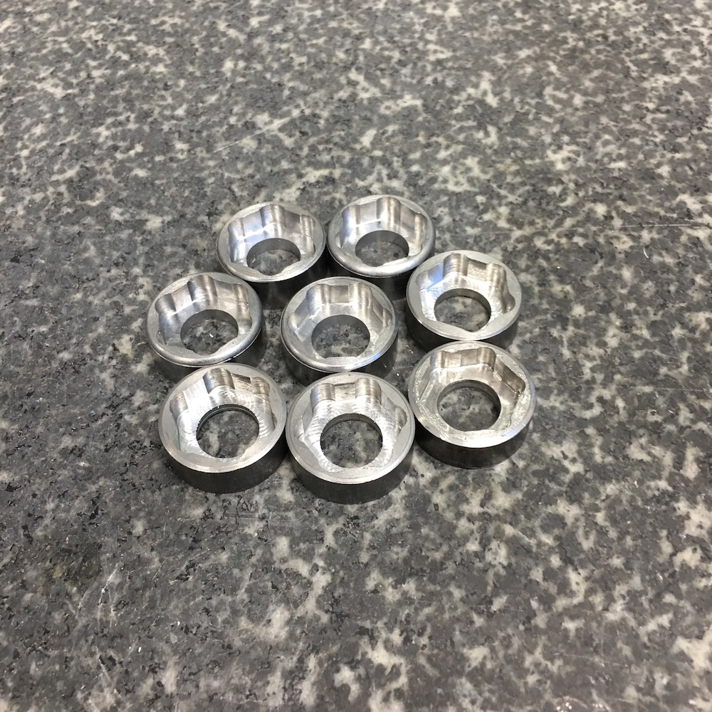
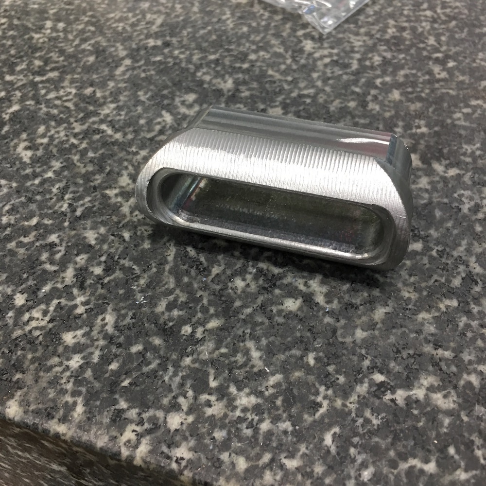
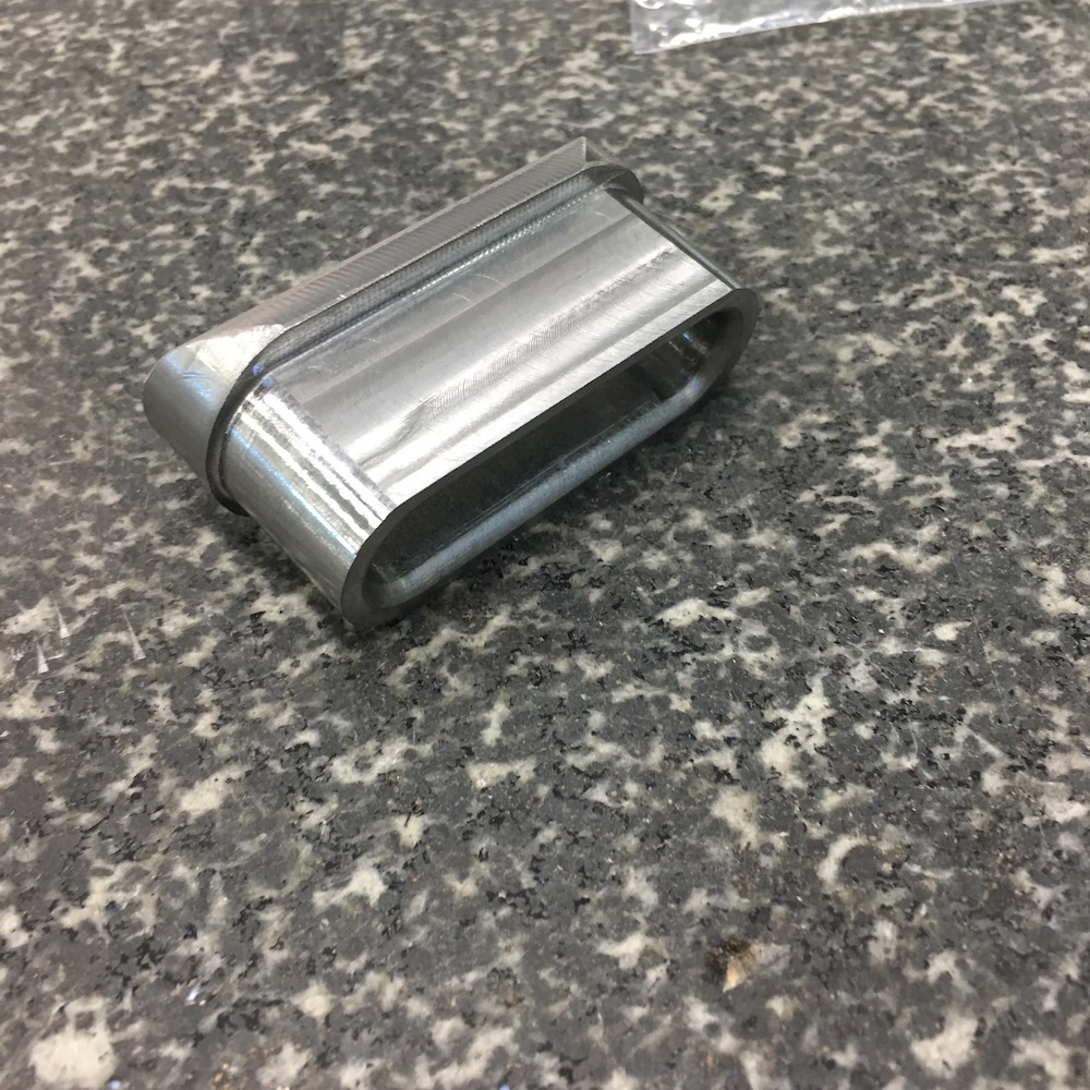
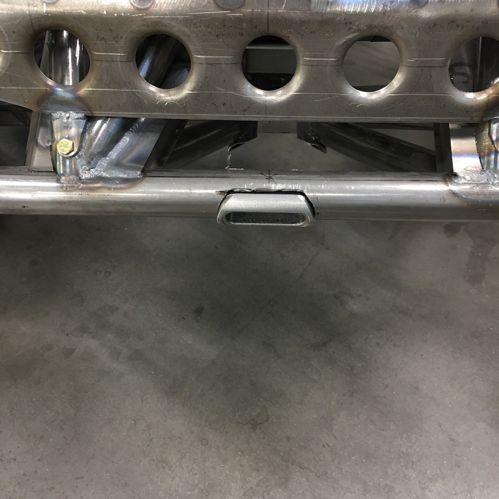
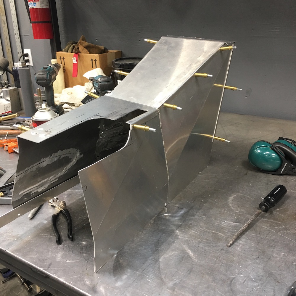
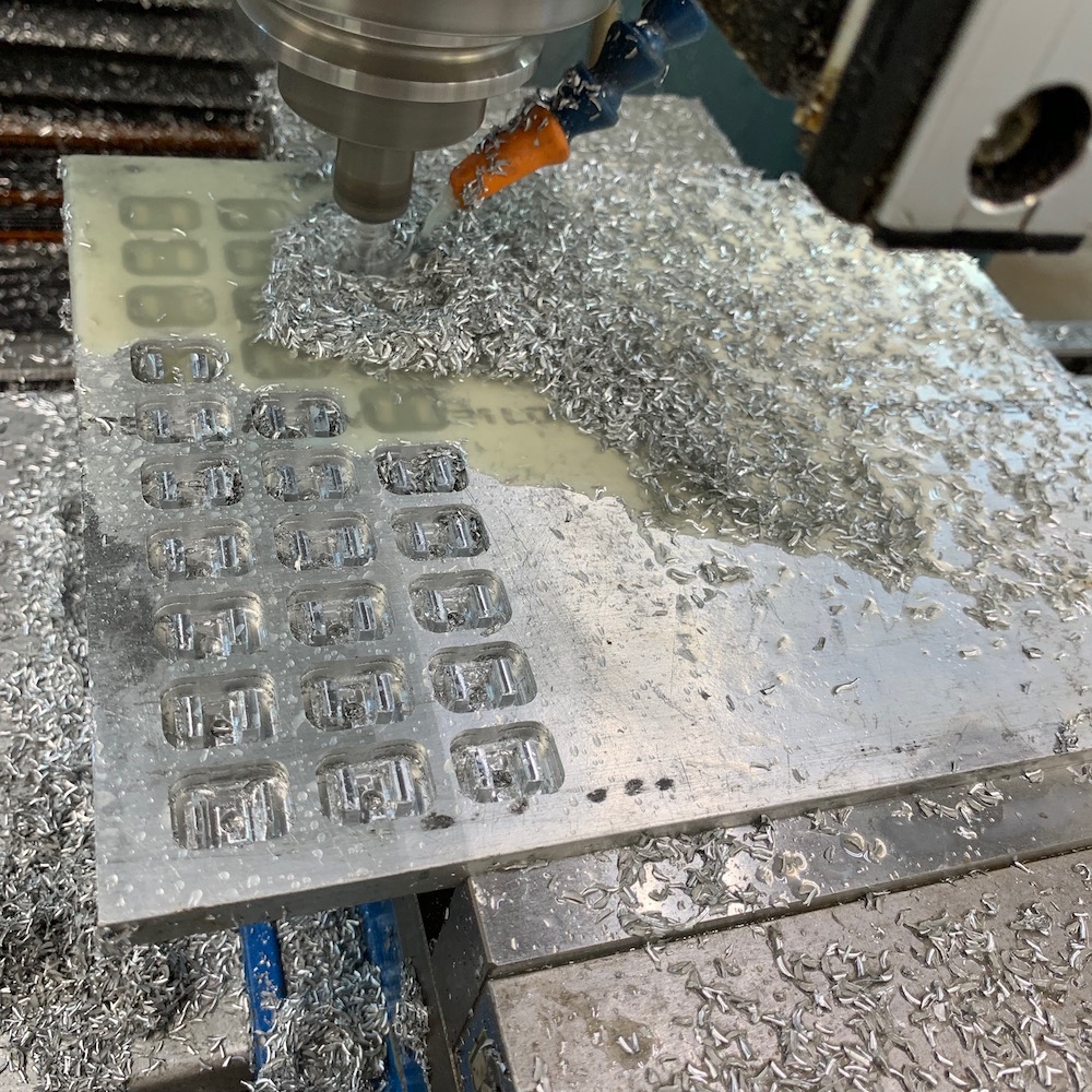
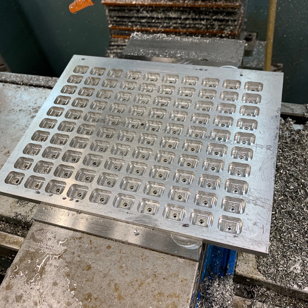
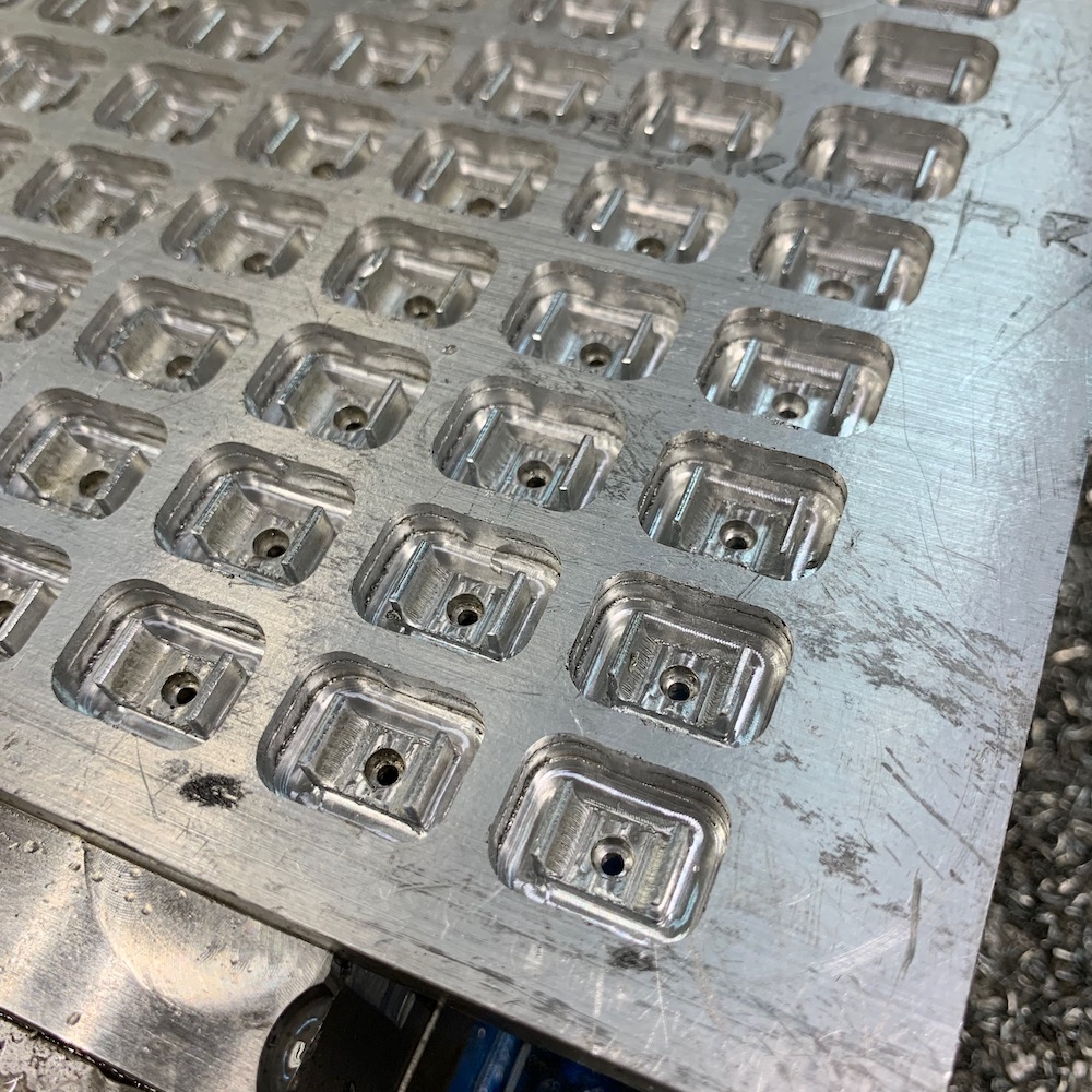
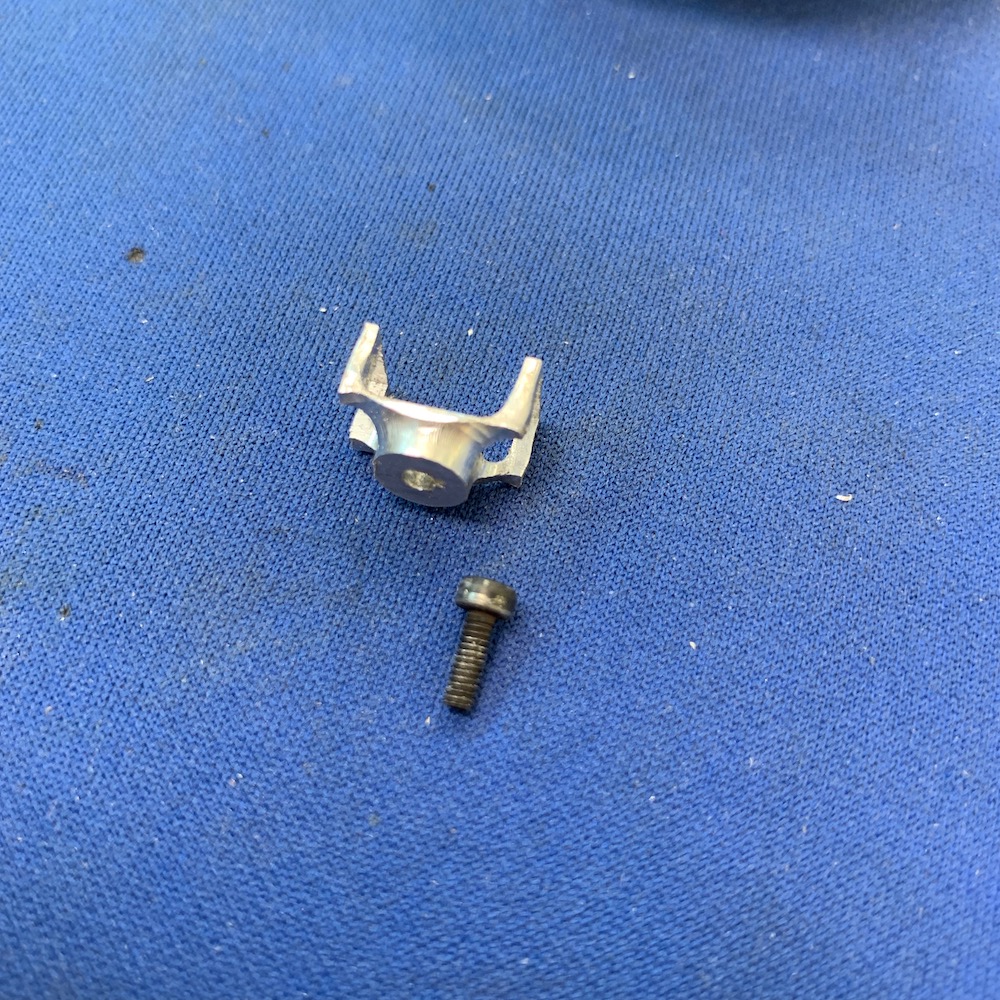
Got another set of nuuuuuuut pockets done for the 1/4" bolts that hold the tail section on and for anything else that may end up running through a 1.5" tube:
Pulled the engine and am working on getting the cradle mounted to the tail section of the chassis. Sorry, no pix. Will have them tomorrow, I hope.
Progress!
Jan 6, 2019
Bullnerd
Tig welds dude!
Me
They're getting better more often. By the time I'm done with this I'll be making pretty beads all the time.
Bullnerd
Nuuuuuuut pockets! (You know I have to!)
Me
LOL - I'd be disappointed if you didn't. Hell, I sing it when I make them.
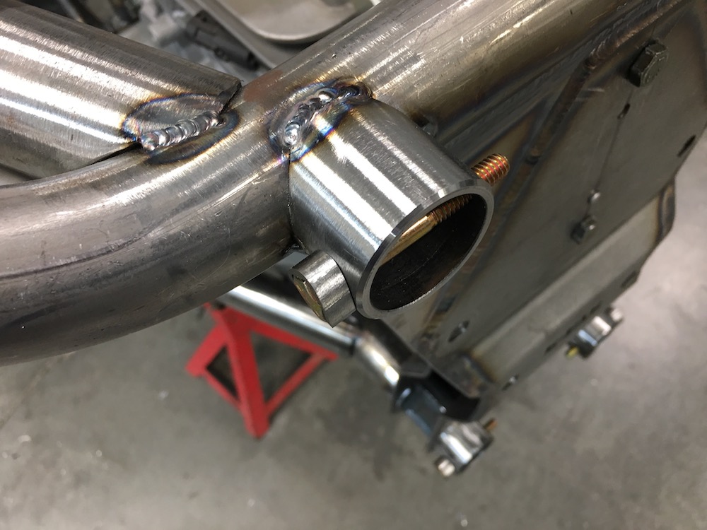
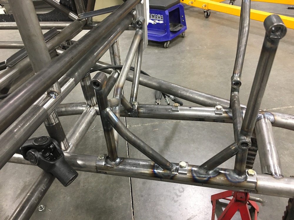
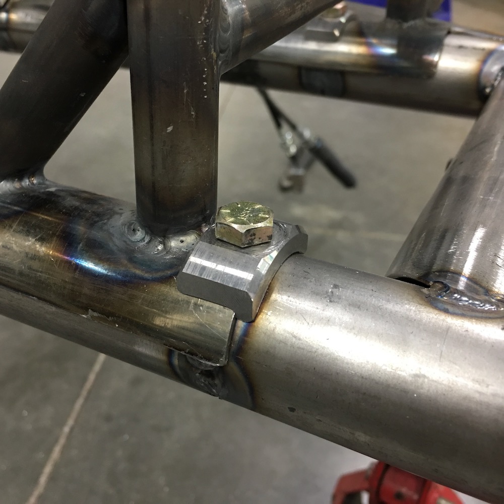
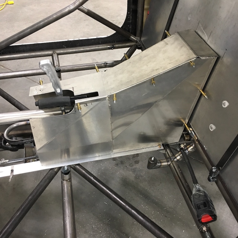
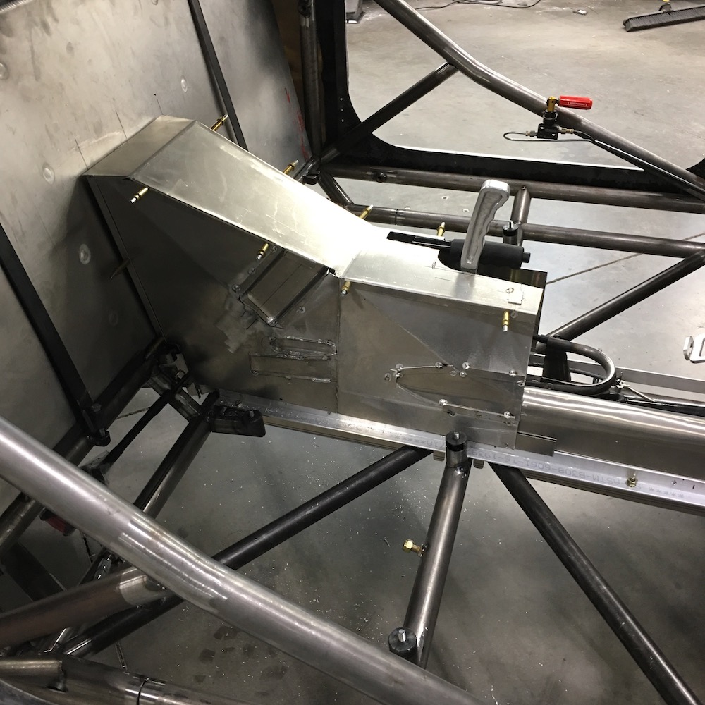
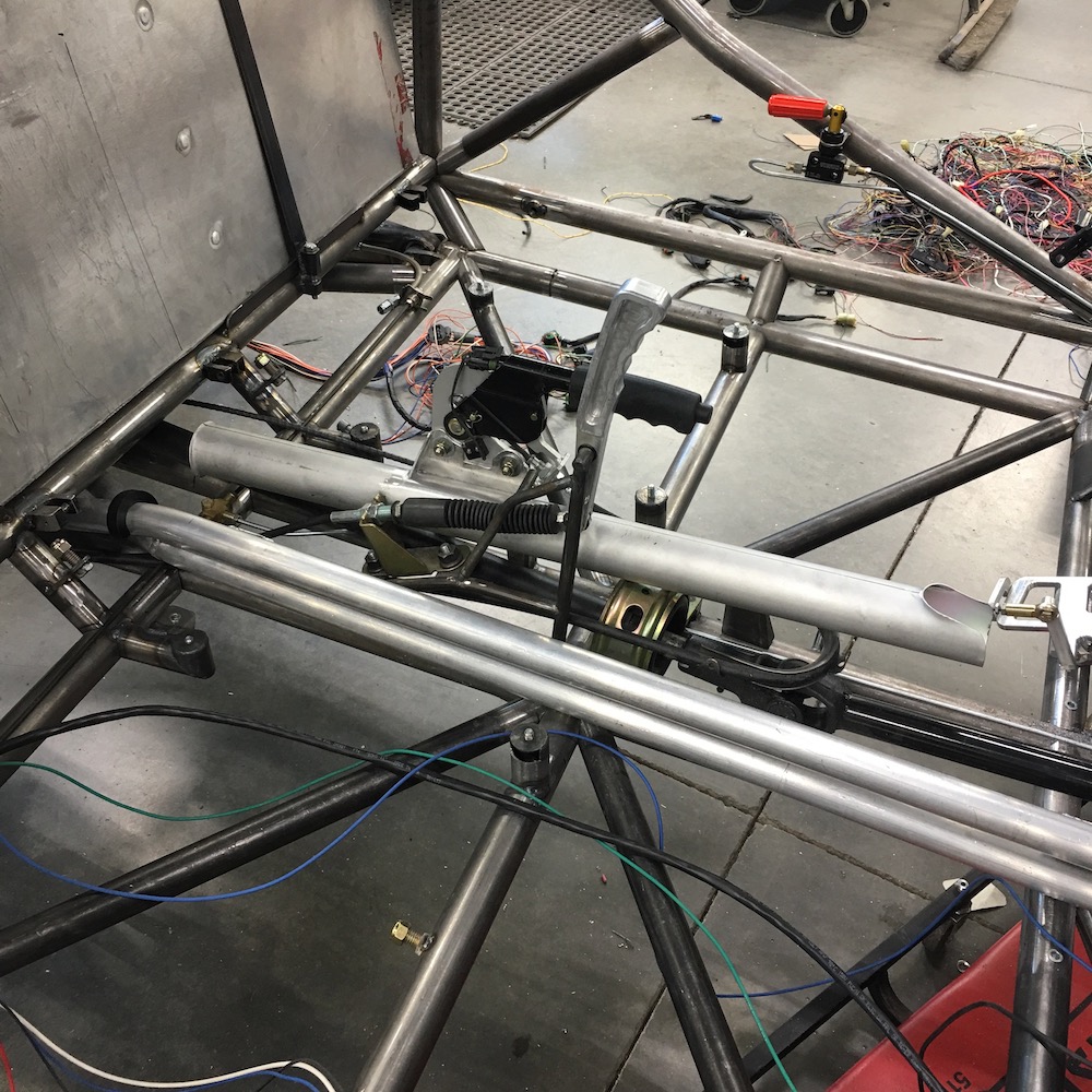
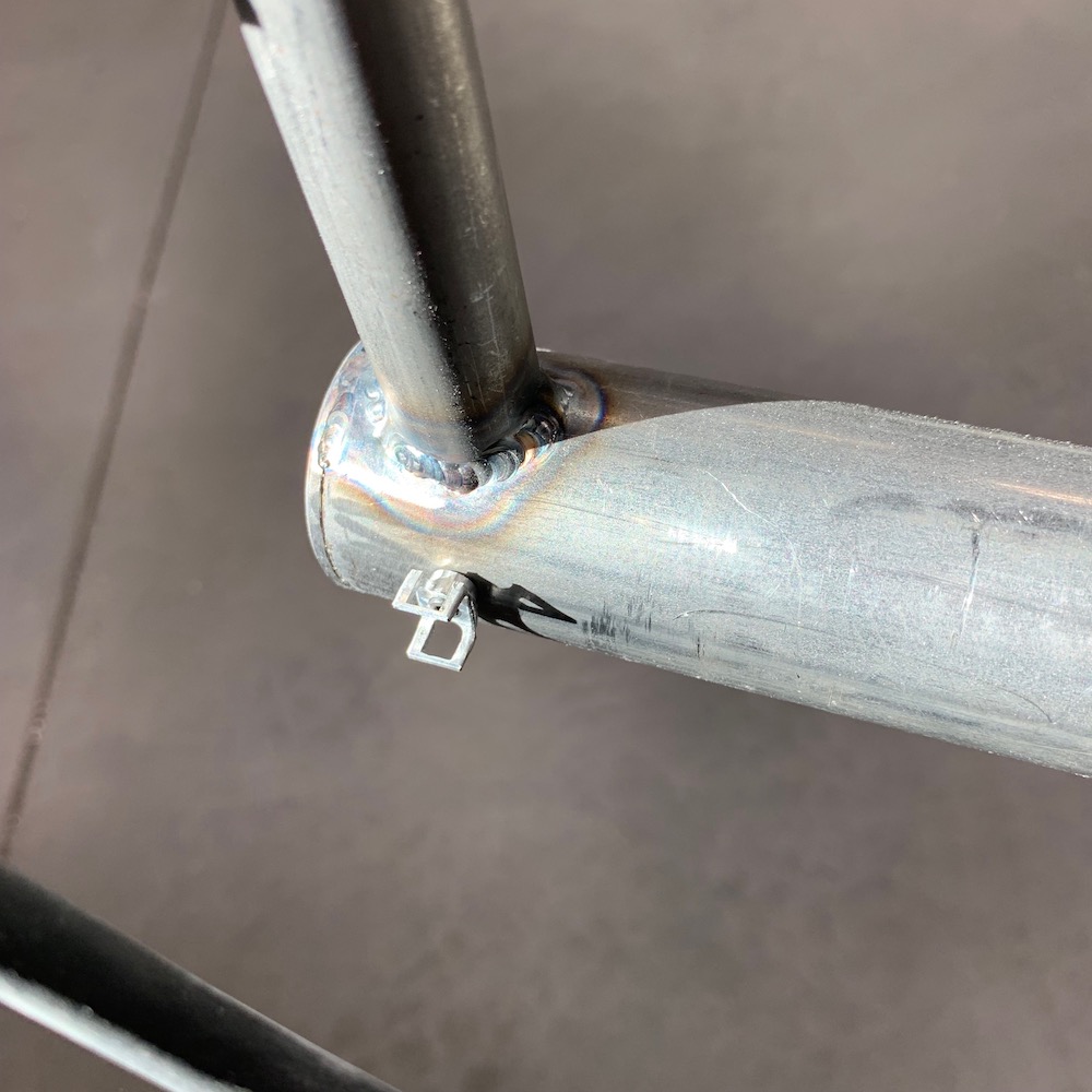
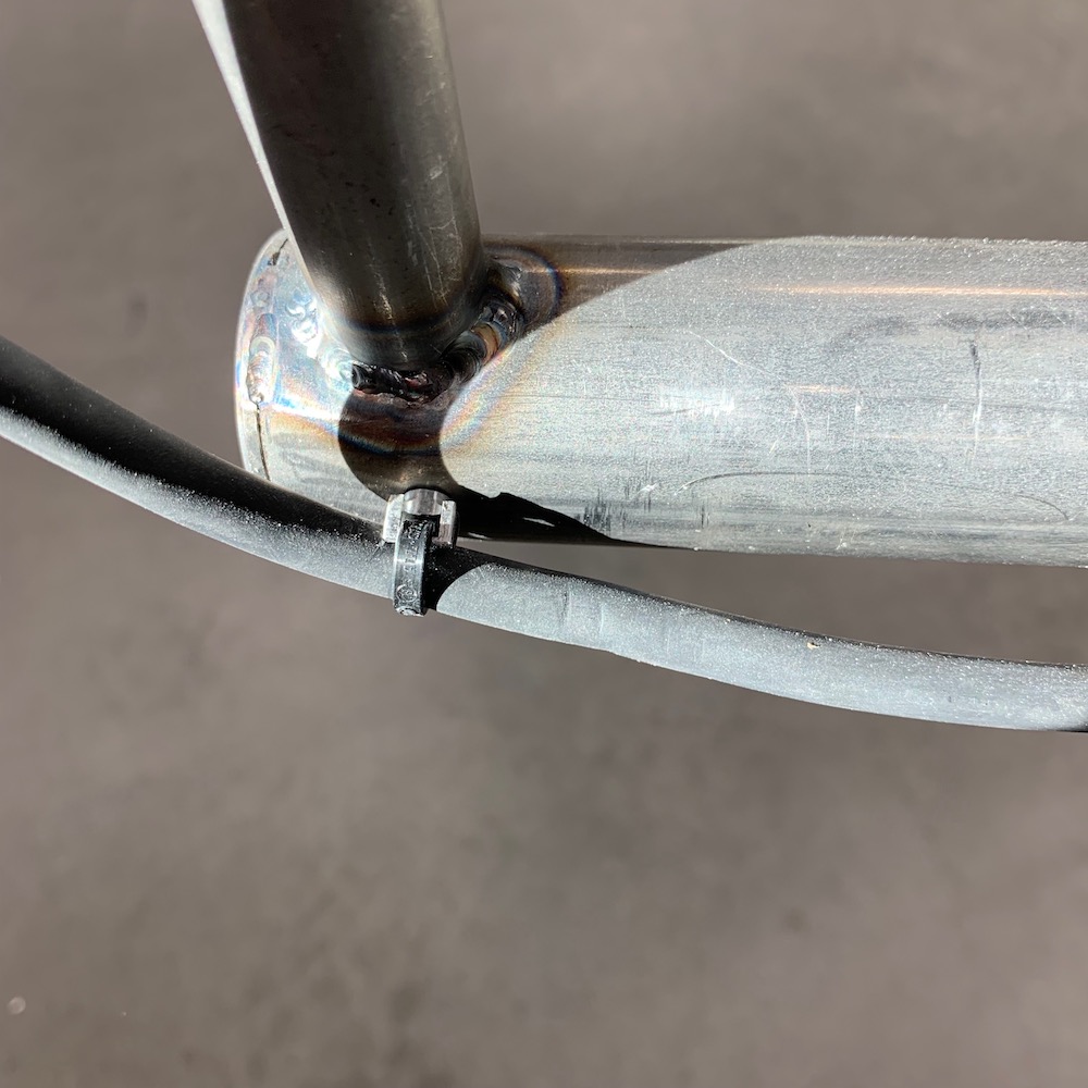
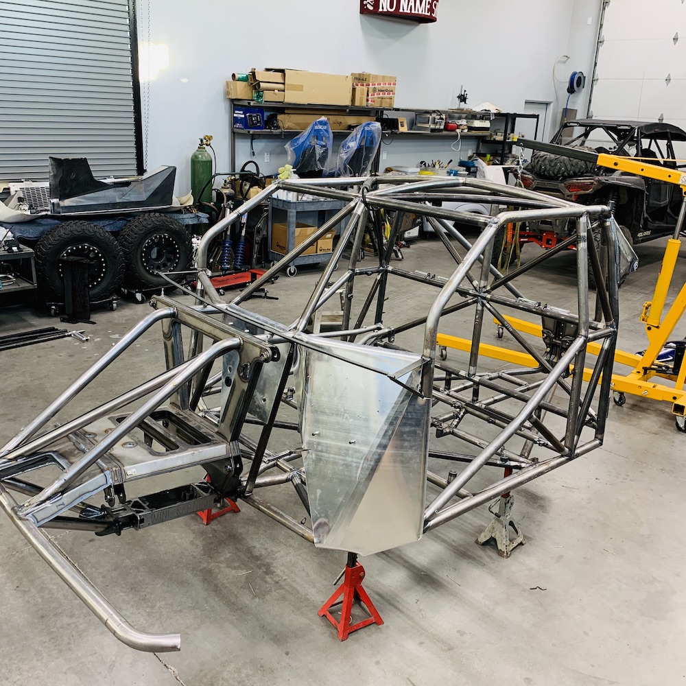
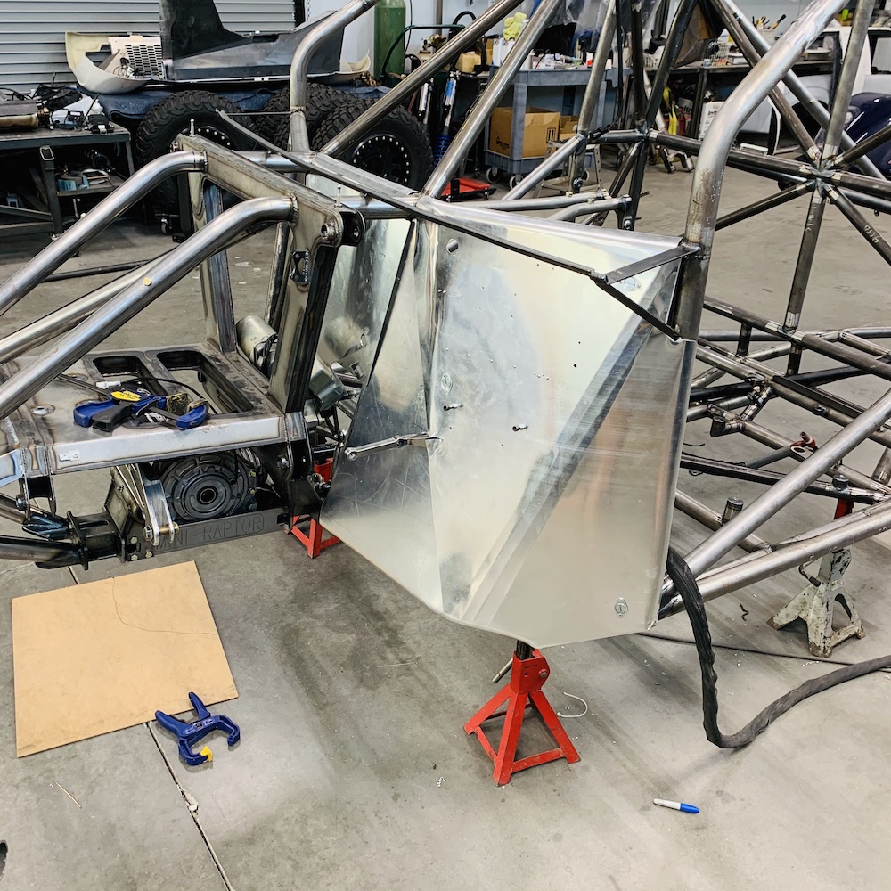
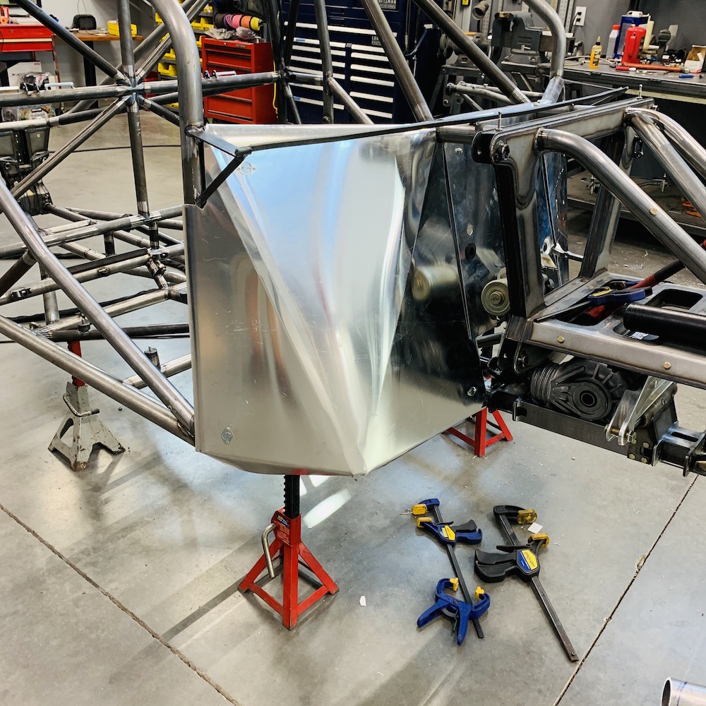
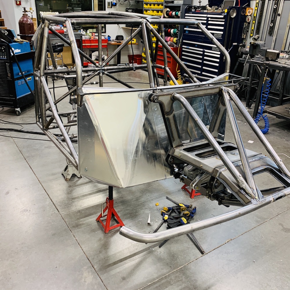
Engine cradle is mounted. Caps hold the split tubing down to the main rails and there are .700" wide threaded slugs in the tubes so it's one big set of pinch clamps. Of course I forgot to put the slugs in back before I mounted the rear bulkhead so I had to cut out a section under each of the cradle's mounts. The slugs act as inserts at the joints so everything is nice and tight. Thank goodness for powder coating - it's gonna cover up a BUNCH of things that don't need to be seen. LOL.
I shouldered the end pieces on this side just for grins.
The six caps came out of a piece of 2" x .25" wall tubing. I did the machining on the end of the tube, leaving four fingers sticking out and then parted them from the tube in the lathe. Man they make some noise when they come off. THWACK, THWACK, THWACKITY THWACK! I stayed well behind the shield and used two fingers to operate the feed. Spooky stuff sometimes.
Gonna get the fuel system installed before I drop the engine back in so that's next in the cue.
Jan 10, 2019
Things are happening.
Engine and trans system are mounted.
Cooling system is finished (except for where I plumb in the HVAC system a bit later)
Fuel system is 90% - still have to make the bung that the return line goes to and weld it to the tank.
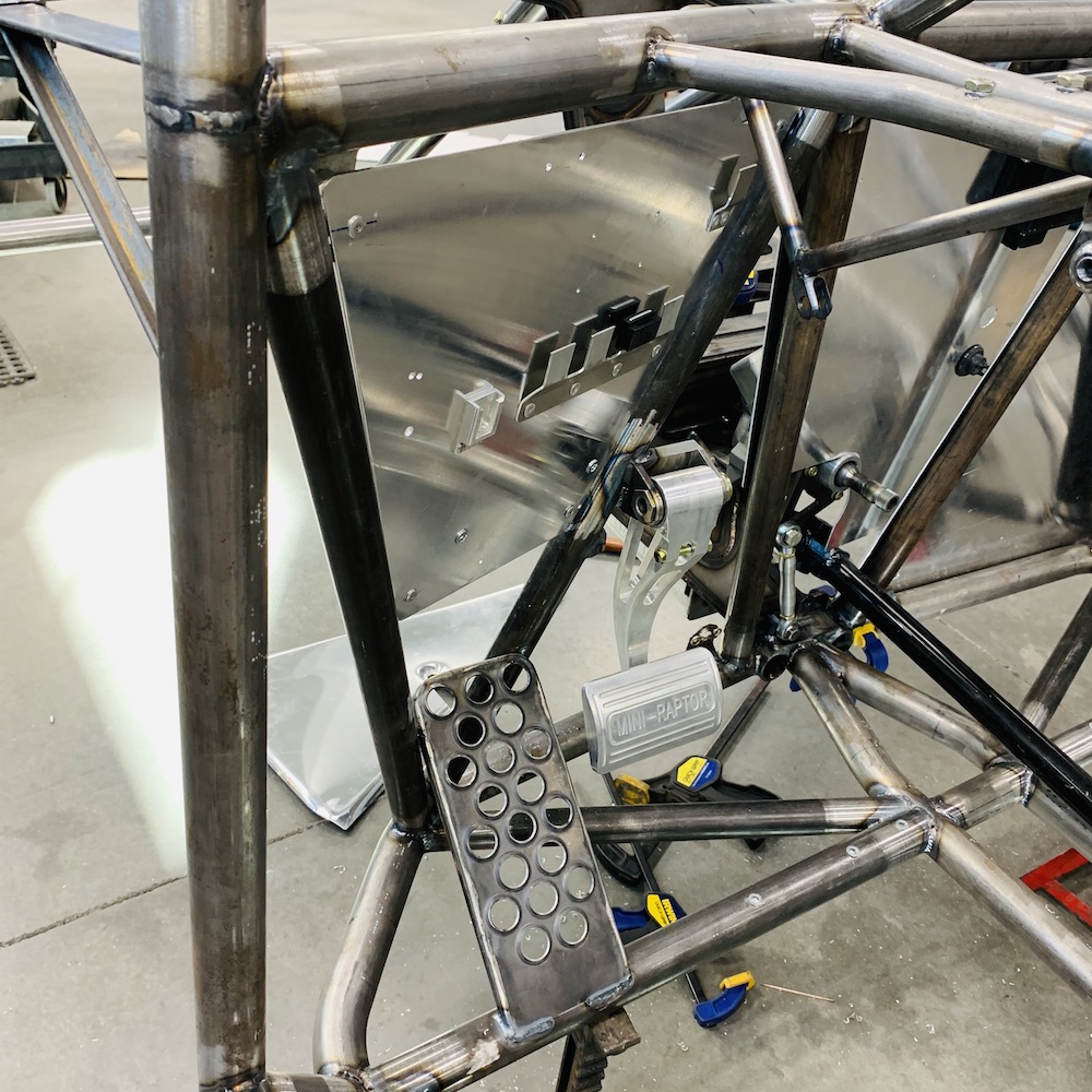
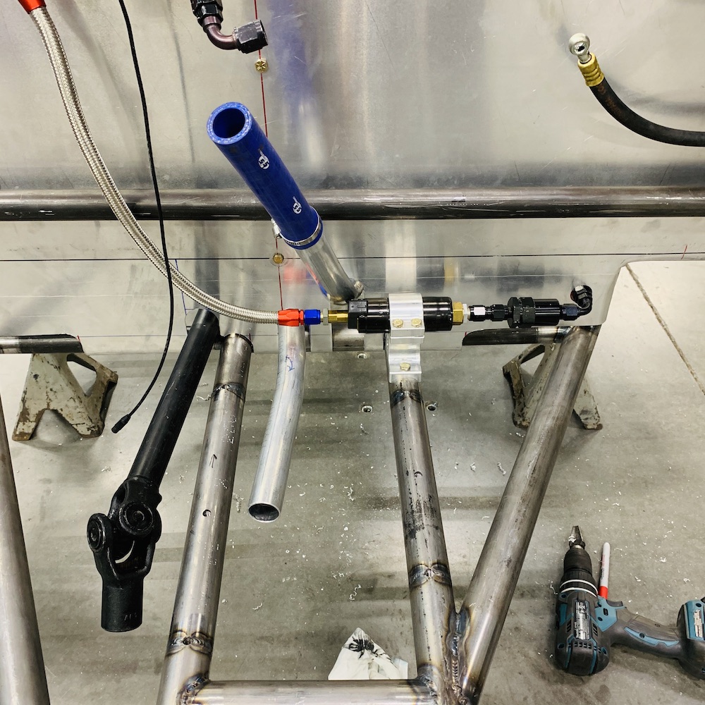
Billet! Pump mount in process:
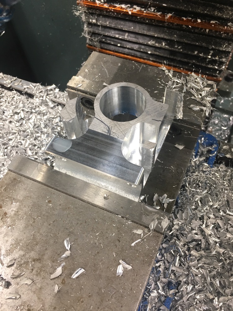
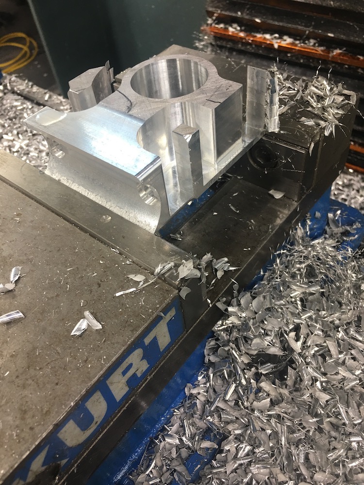
Pump mount (insert "tada!" sound):
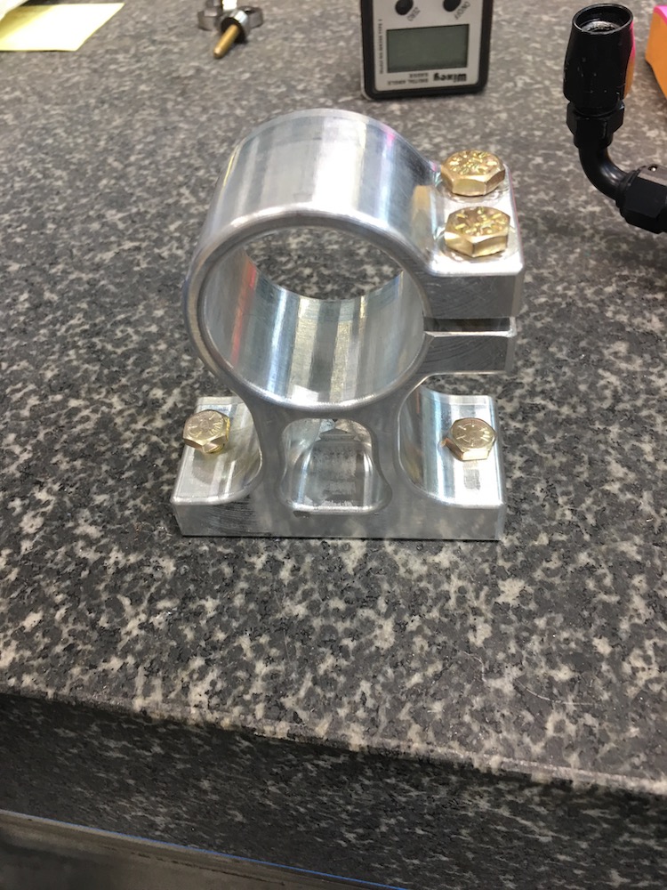
Bench fitting test - perfect!
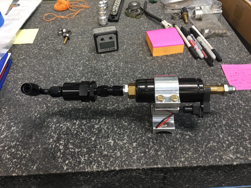
Frame fitting test - perfect!
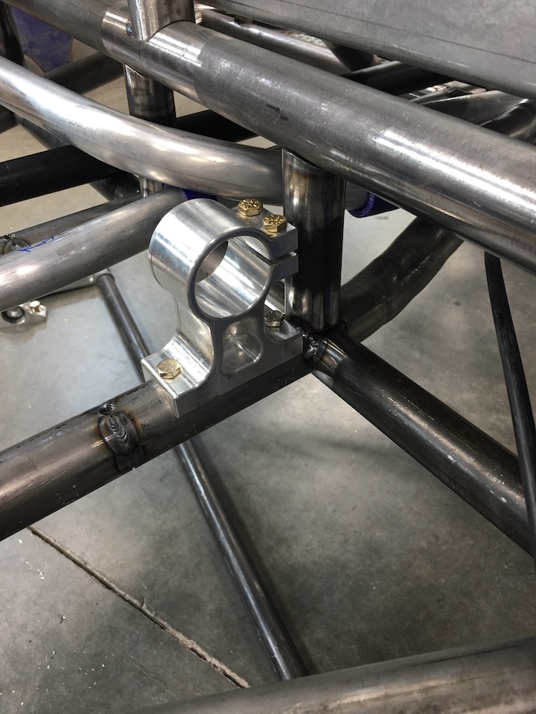
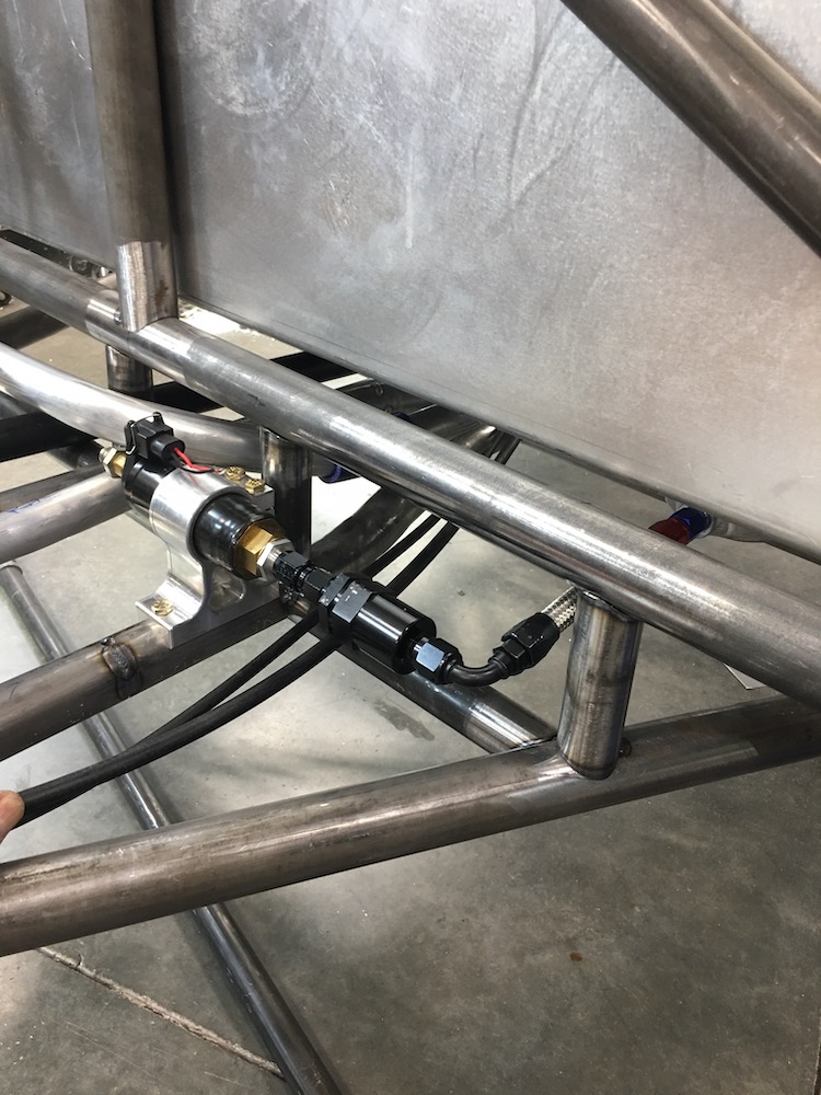
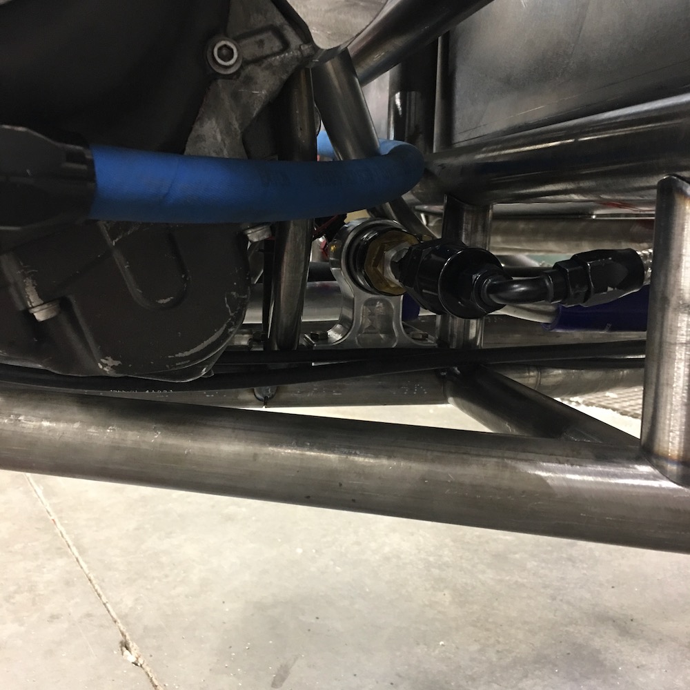
She's tight but everything clears and has room to vibrate and move a bit:
I'll get the final piece for the return line done today and hopefully tacked into place on the tank (tank is a bitch to install/remove - may have made it a tad too big up top but it fits).
Once that's done it's exhaust system time. I have the stock Nytro system in hand and want to see how much of it I can use. Not sure it's going to be quiet enough, though. I want this thing to be whisper quiet so what muffler finally gets used is still a mystery.
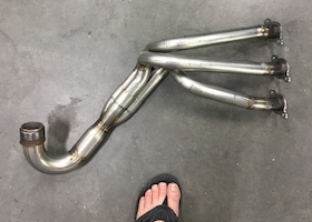
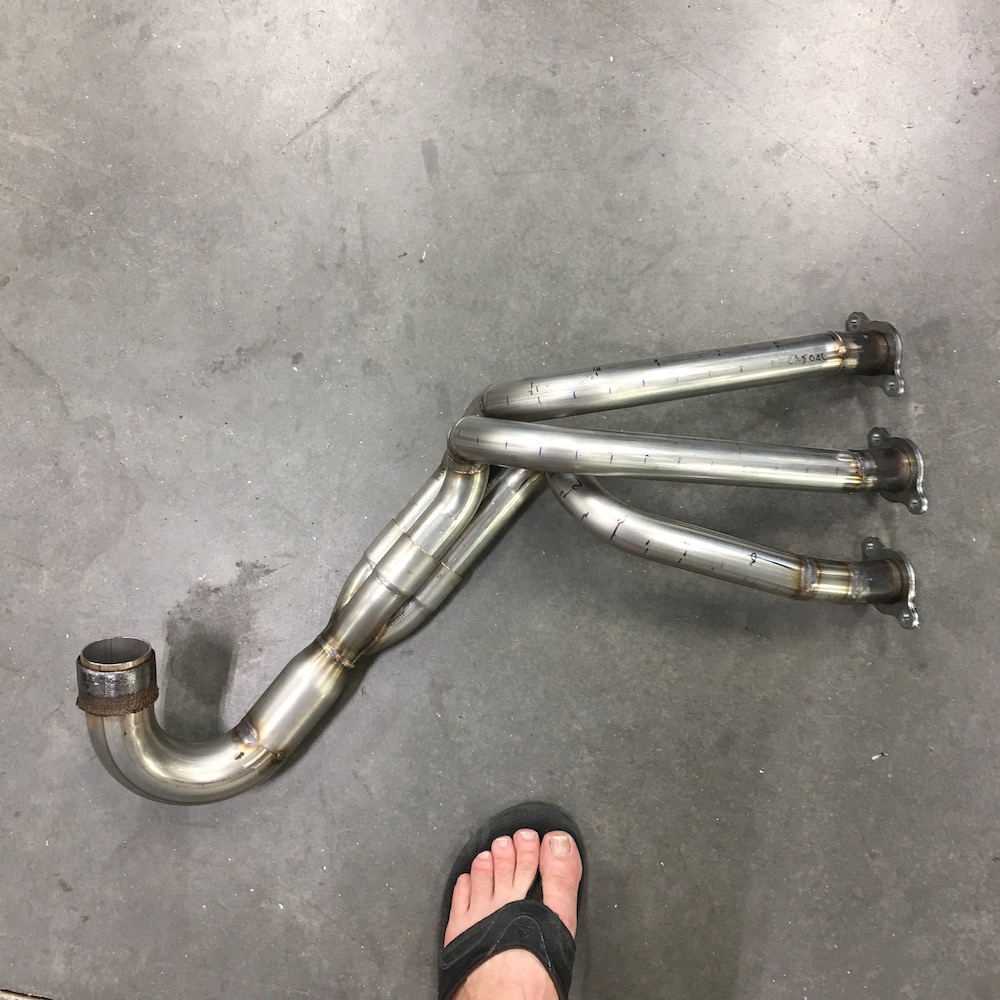
Four J bends, a 3 into 1 collector and two feet of stainless tubing on order from SPD.
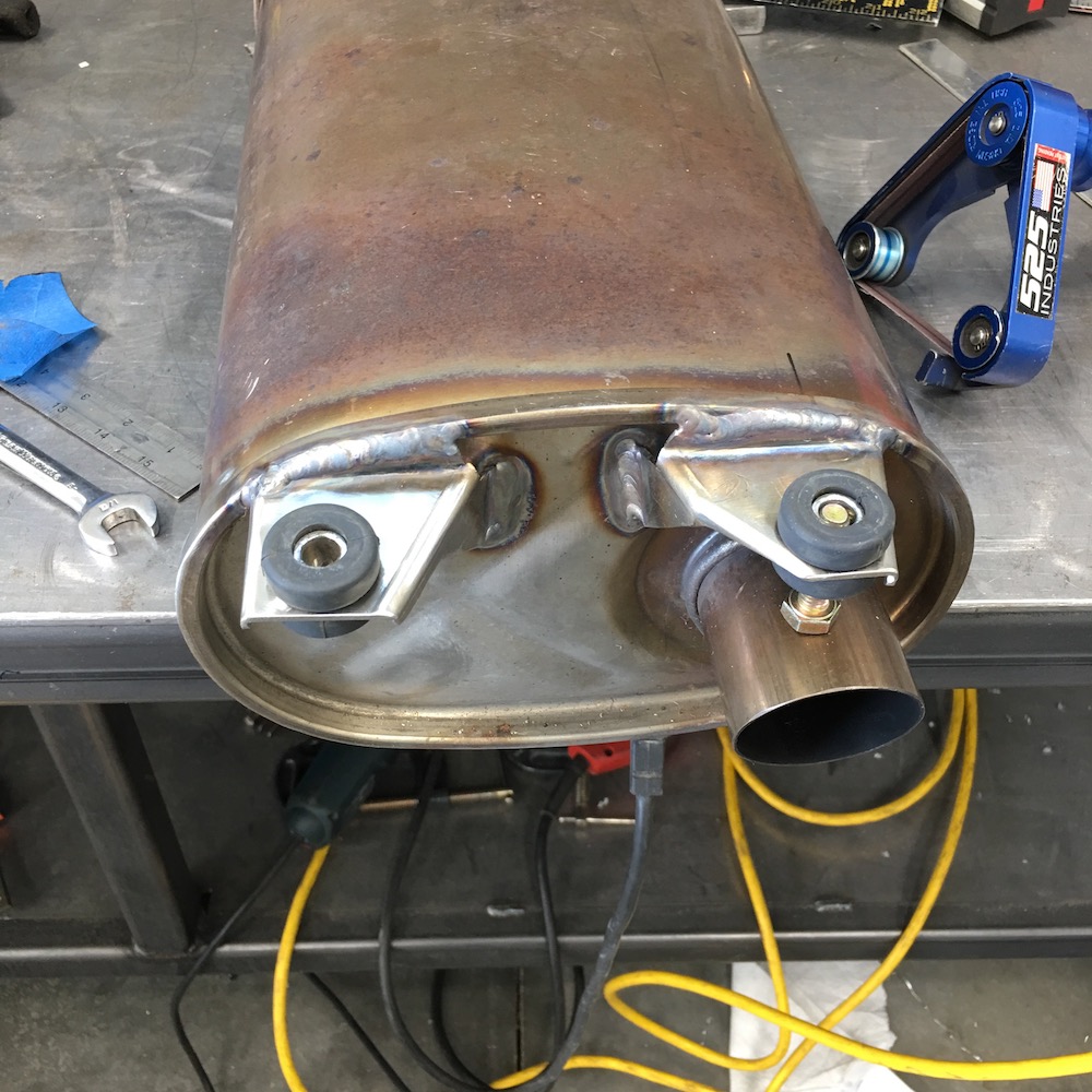
Got the stock muffler installed half way.
The stock mounts are two on each end and one set on top, one set on bottom. I cut the bottom mounts off the exhaust end and made a new upper mount. I'll stick with the two per end setup and knock out another one tomorrow.
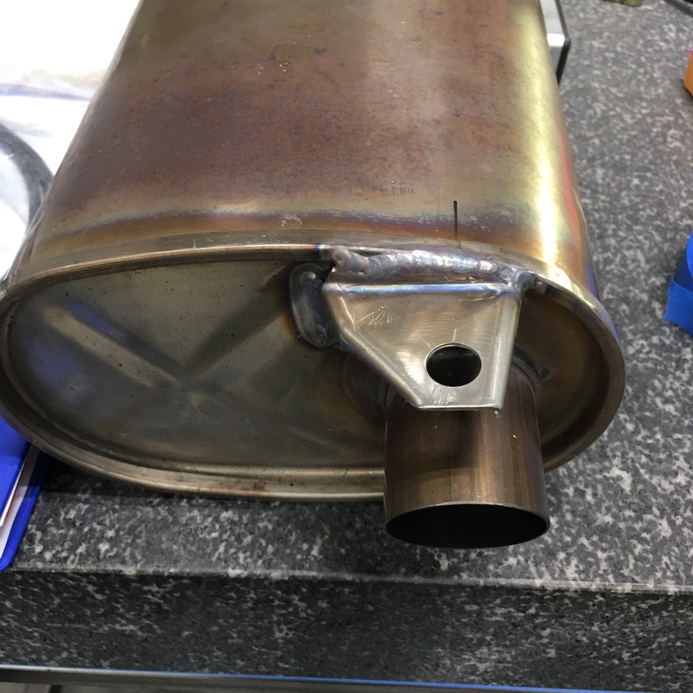
Here's it's new home:
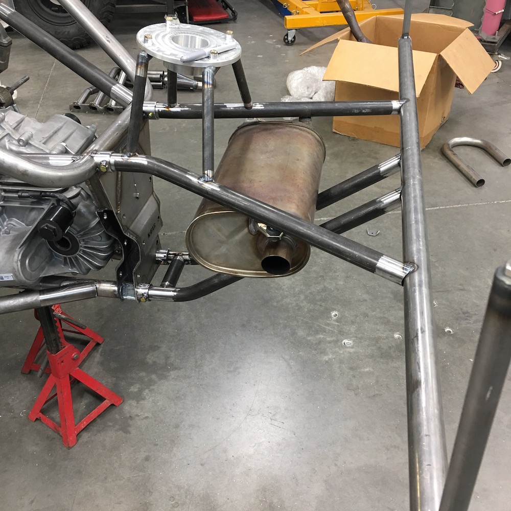
I'll do two ears off the tubes that the front pair of mounts will attach to next.
Jan 11, 2019
Deranged
Any information regarding the exhaust bushings you have on the muffler?
Me
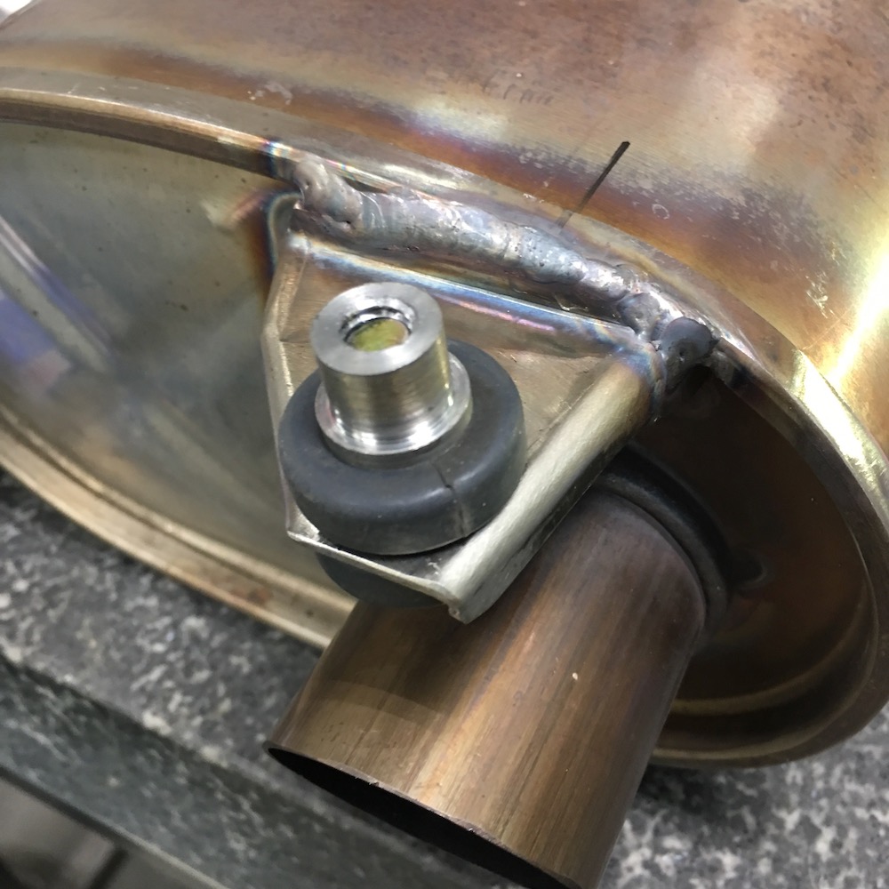
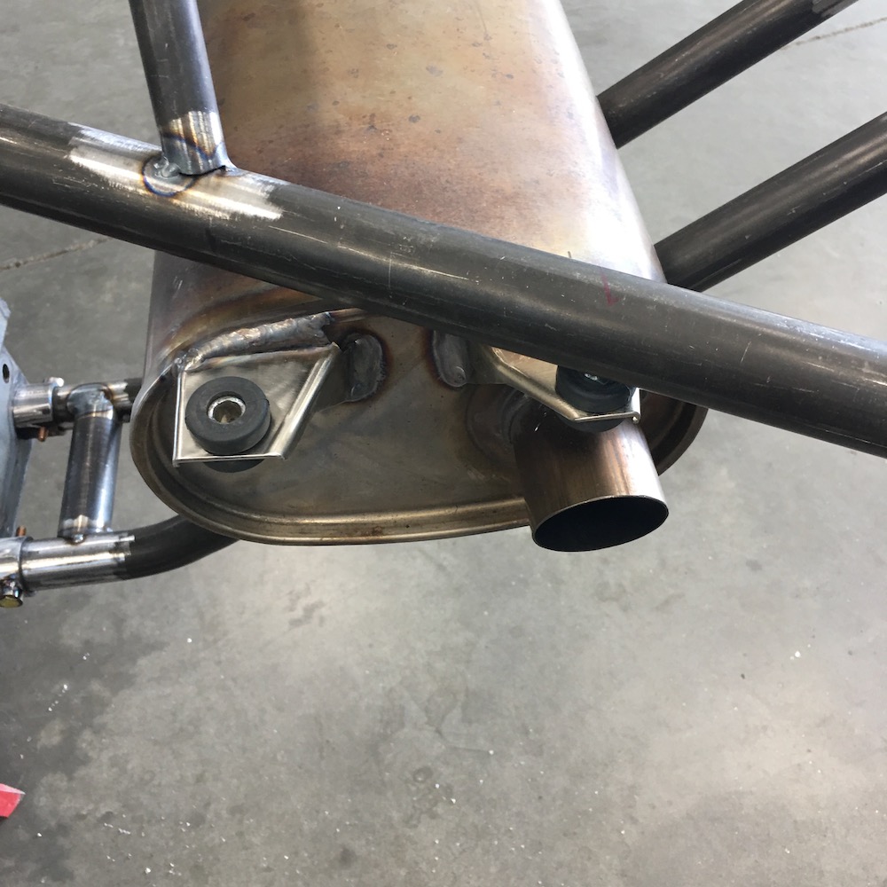
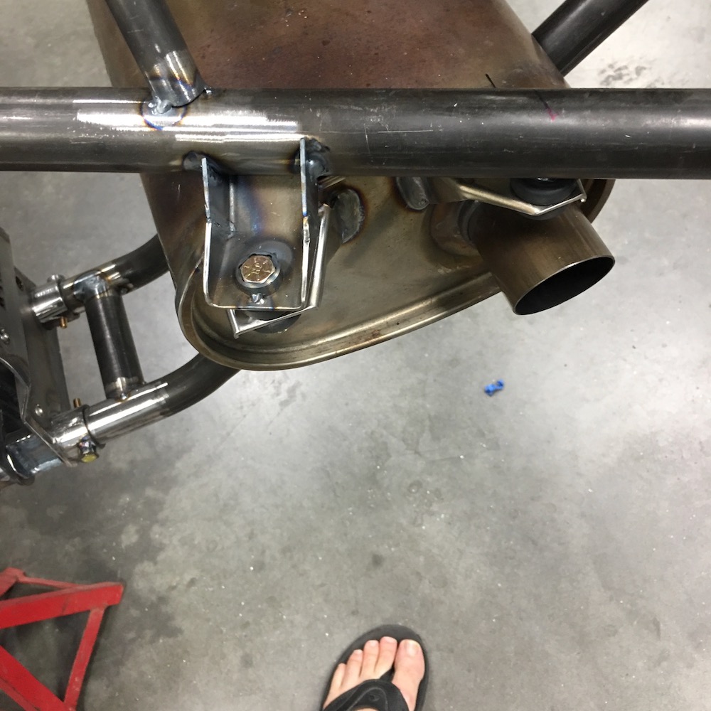
As in what are they and/or what are they from? OEM 2013 Yamaha Nytro exhaust parts. There are four of them on the muffler. Three pieces - steel hat and two bushings. They're sweet.
Speaking of mufflers.
The muffler's mounted in four spots now. Nice and snug.
The two ears I fabbed up:
Another shameless plug for the 525 Industries 360 Degree Tubing Sander
The two mounts that I didn't have to move:
Hey Bull - nuuuuuut pockets!
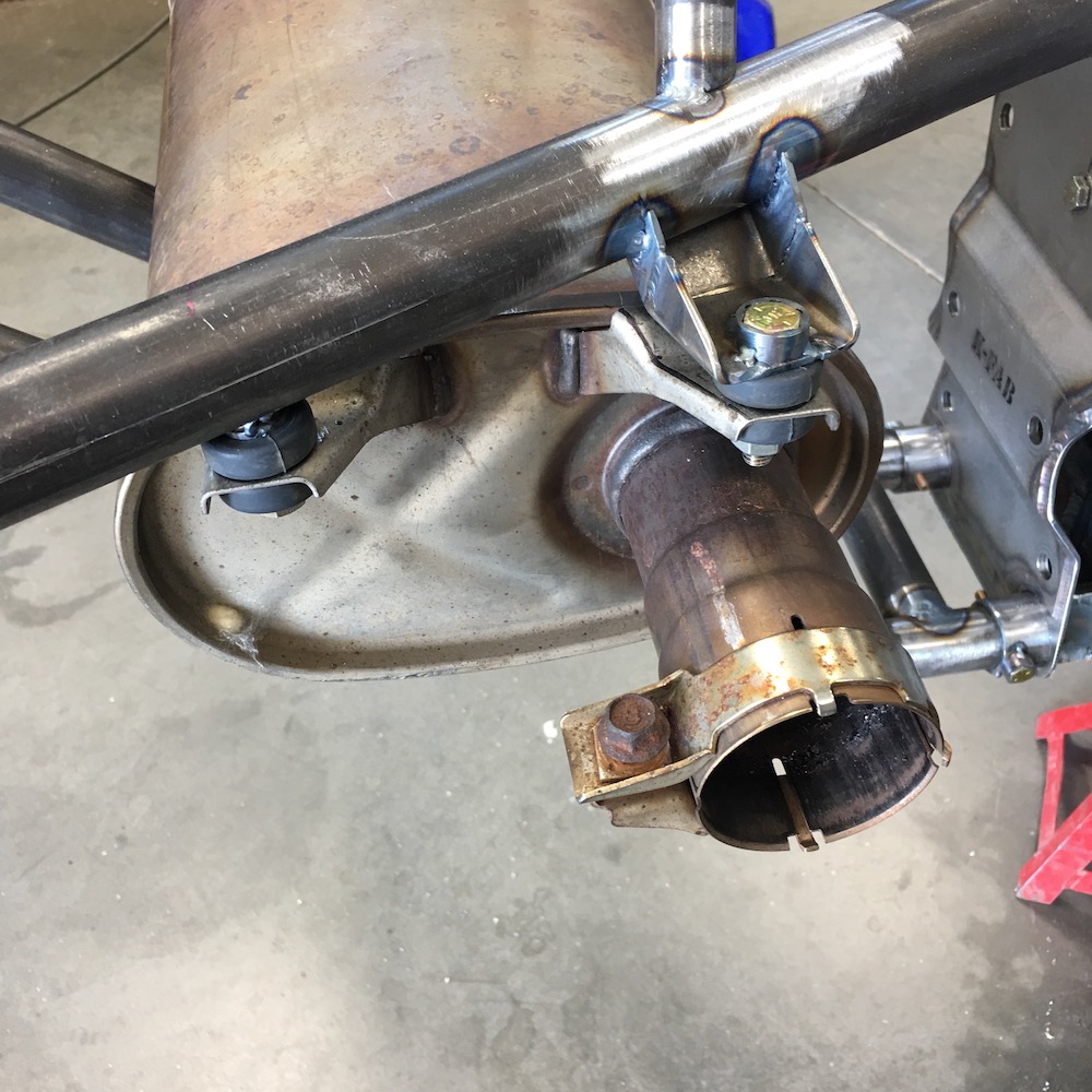
Final tab install:

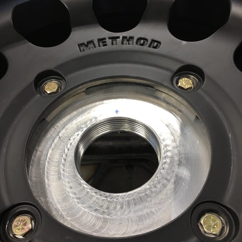
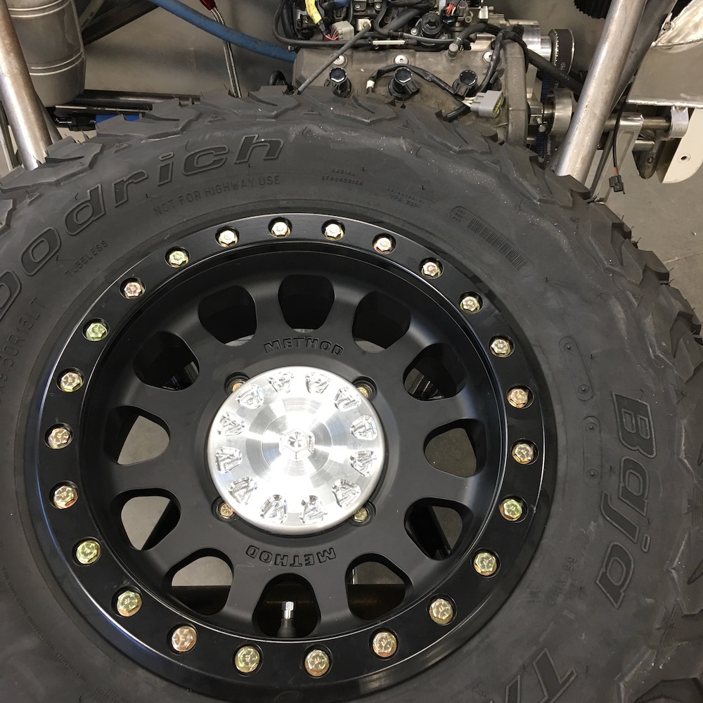
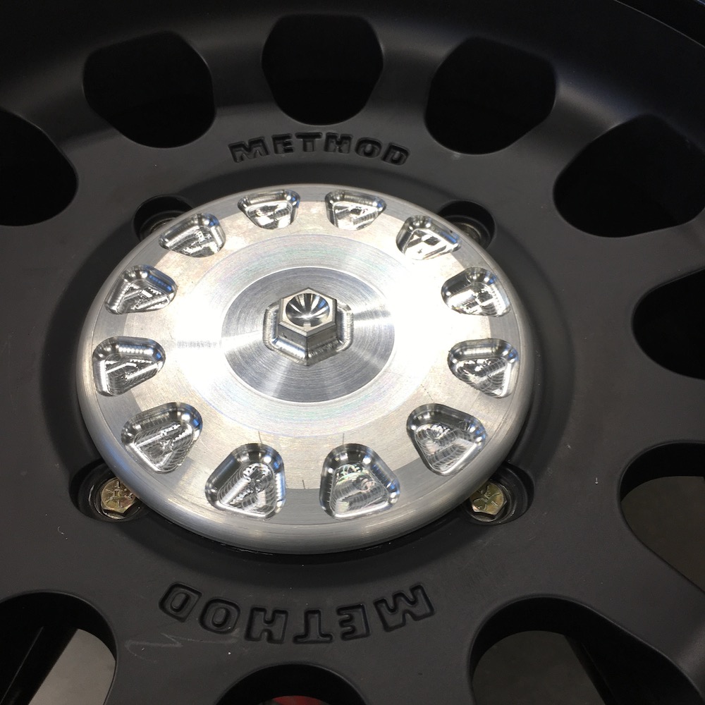
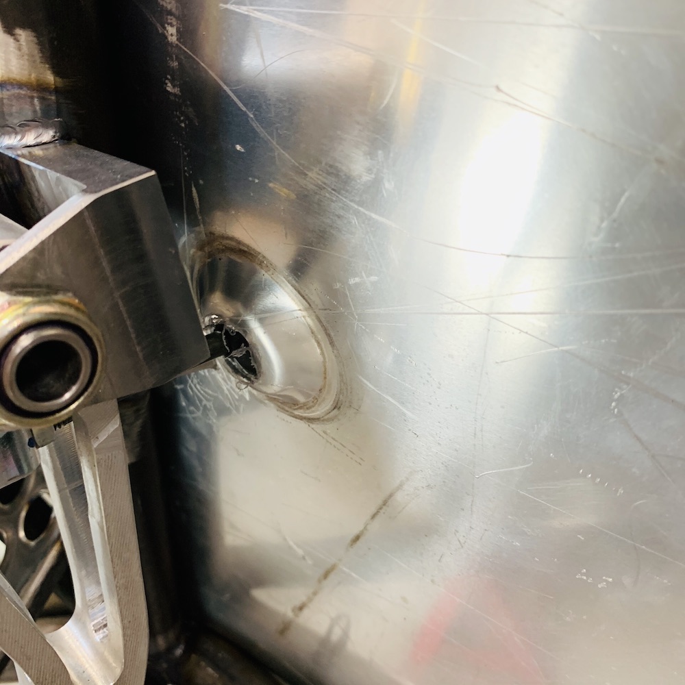
Then I turned to the spare tire mount. I've been trying to figure out how I was going to secure the wheel to the plate and today it came to me. I made a threaded hat that holds clamps the wheel to the plate. It uses the lug wrench (3/4, 19mm). I'll have to be really careful about galling with the aluminum to aluminum. Hard anodize or akadize and lube.
Threaded the throat of the mounting plate:
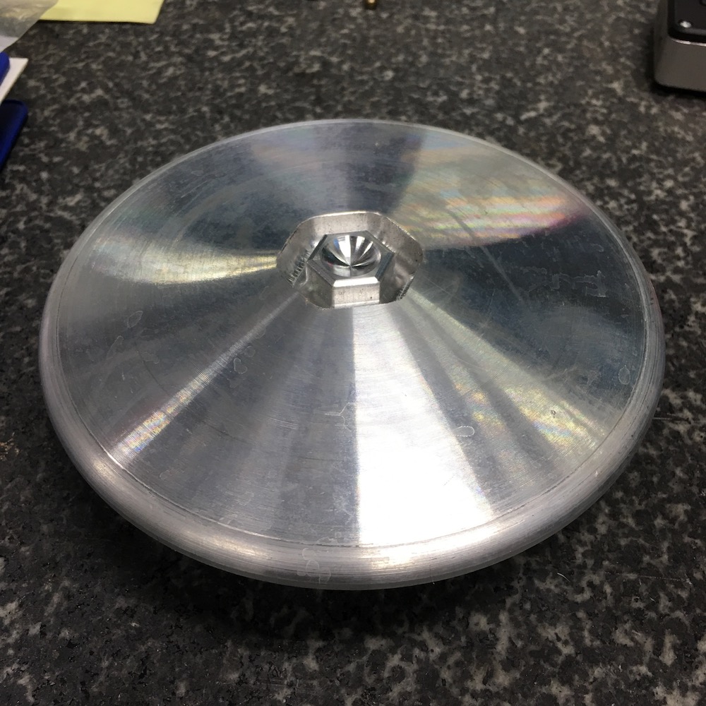
Top of the hat:
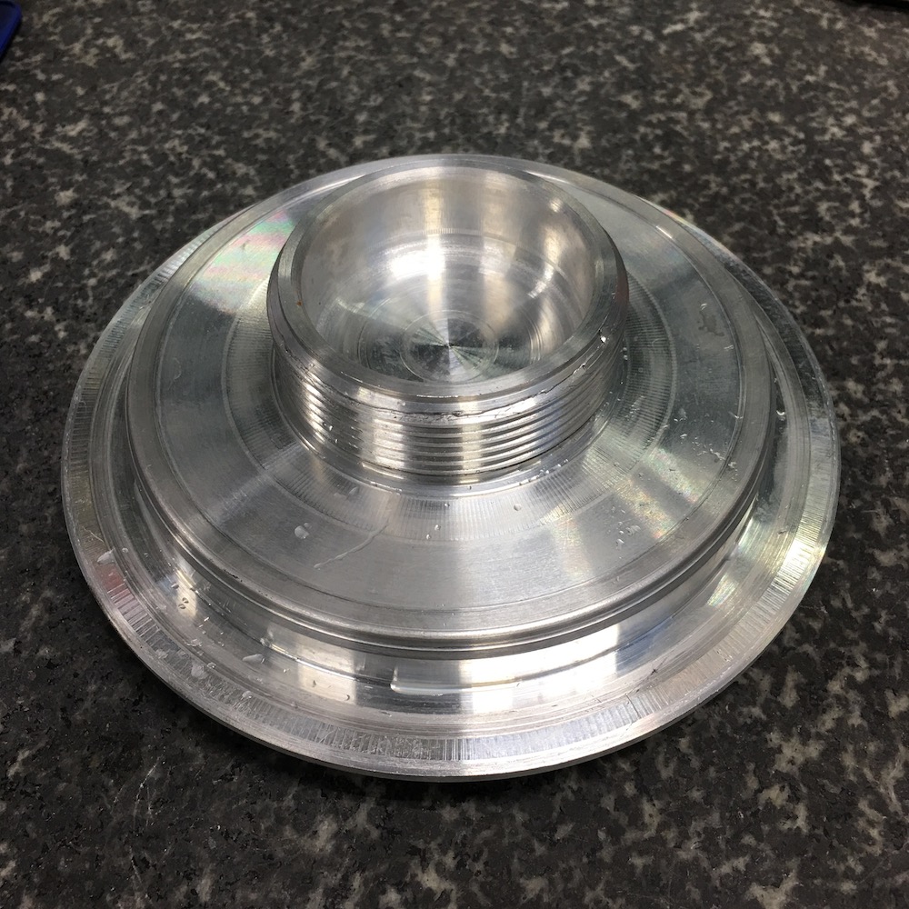
Bottom:
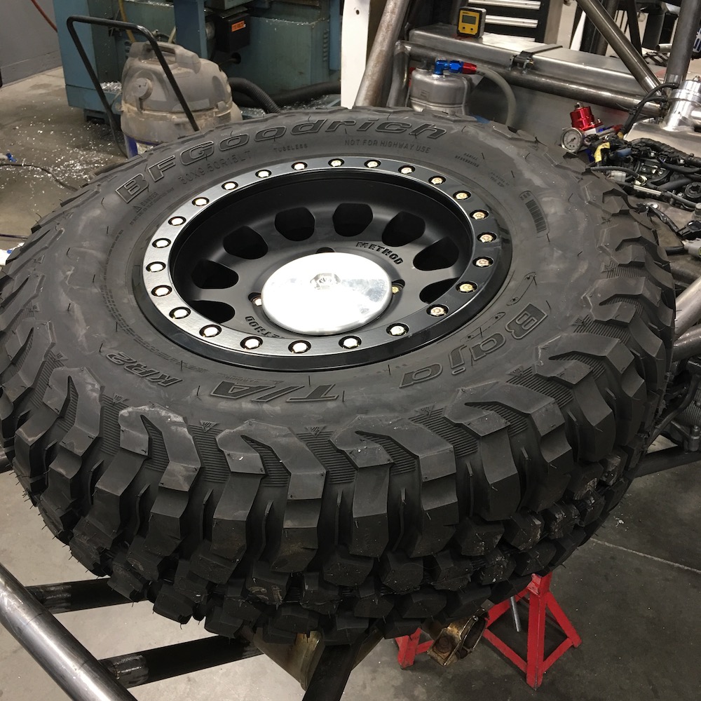
In place:
Dec 12, 2019
Got a lot done today.
Spare tire mount modded for visual pleasure:
I keep expecting to hear UFO type noises and then watch the mounting lug take off and disappear out of the shop and back into space.
Needed more Nuuuuuuut Pockets for 3/4" fasteners:
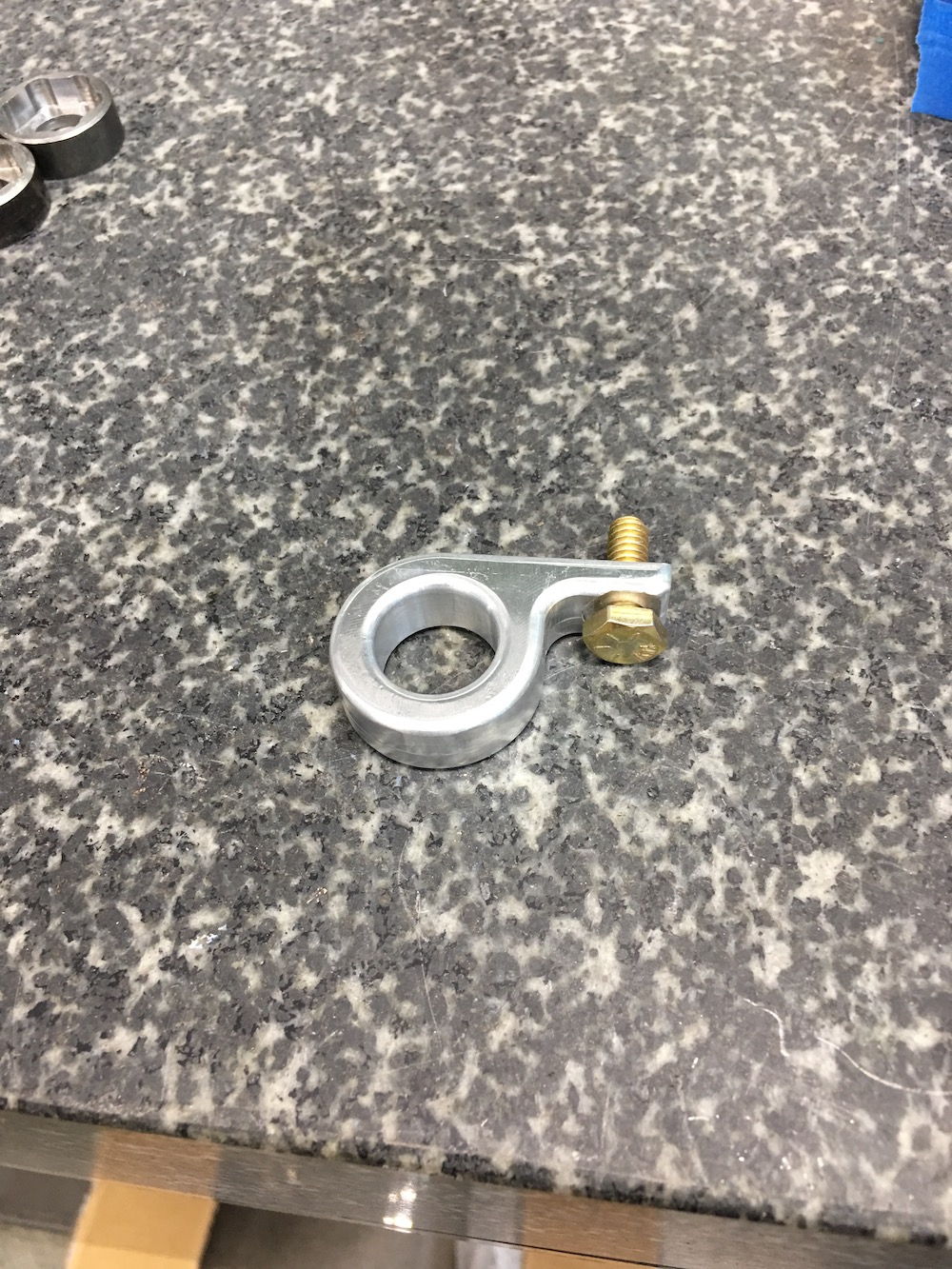
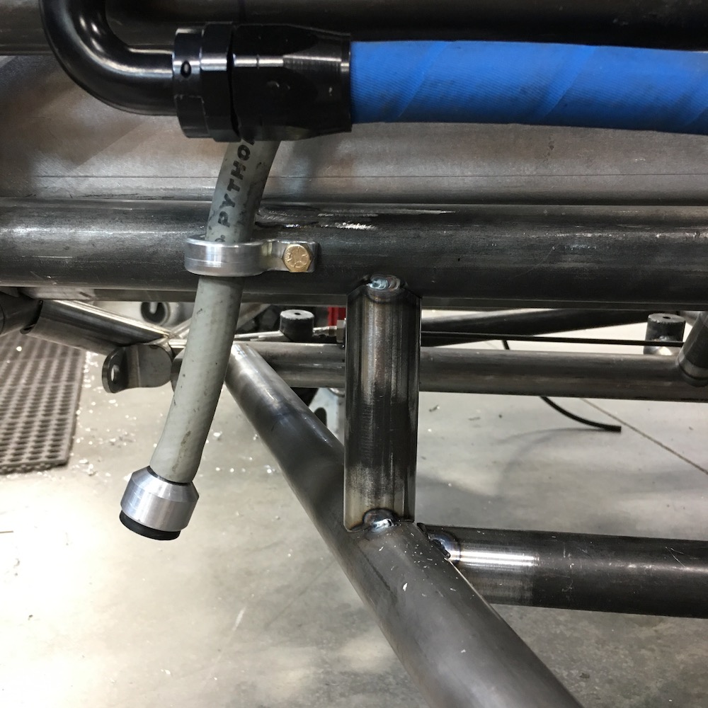
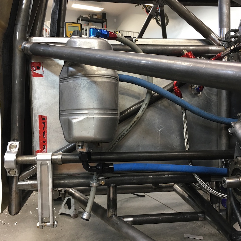
The oil tank has a vent/breather line that needed securing so I made a keeper for it:
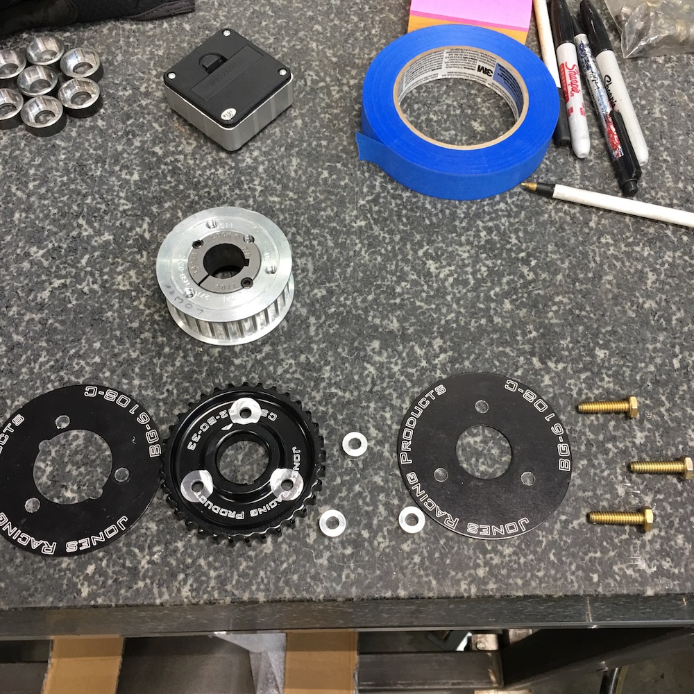
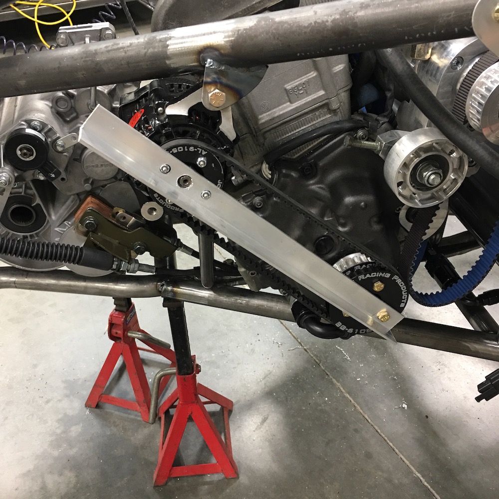
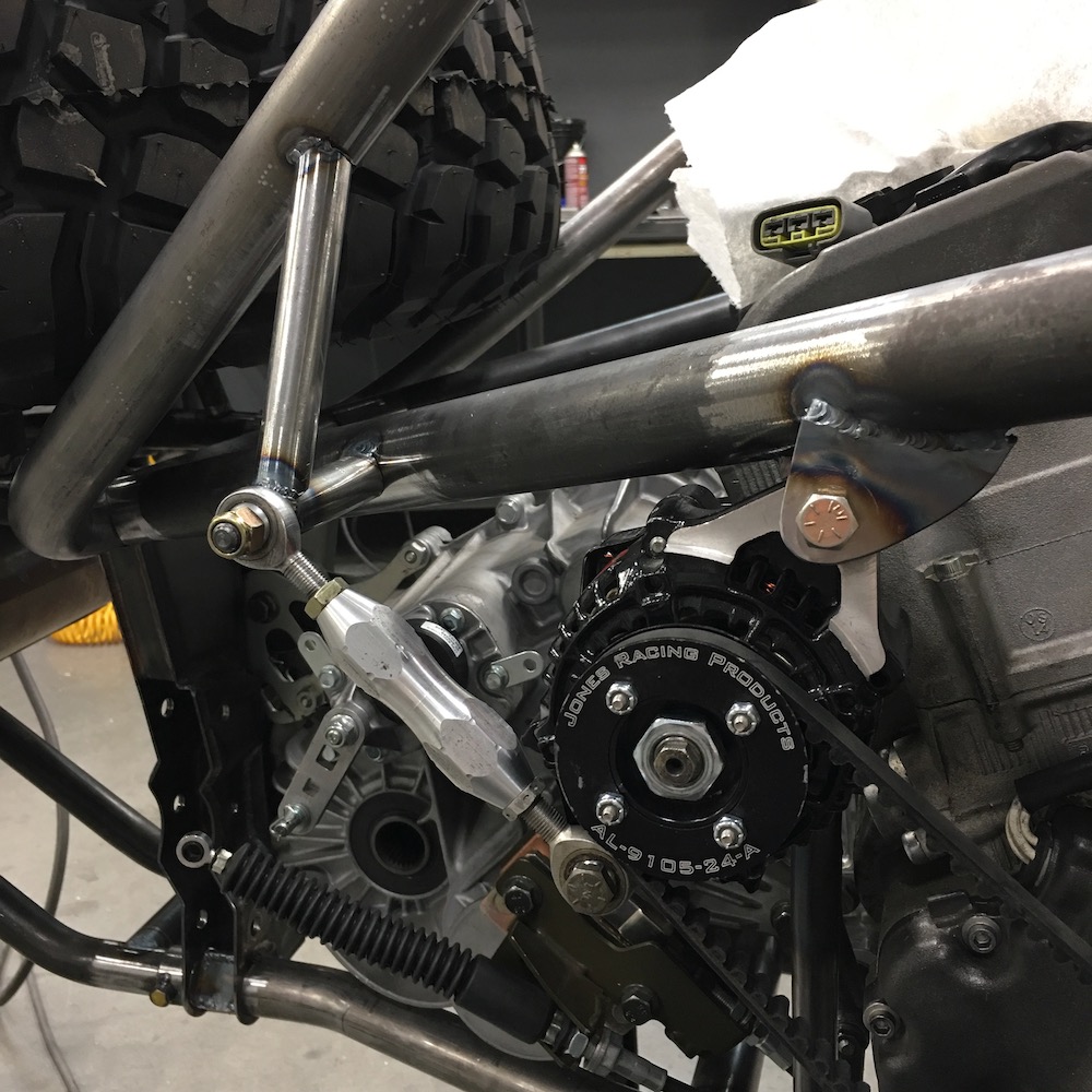
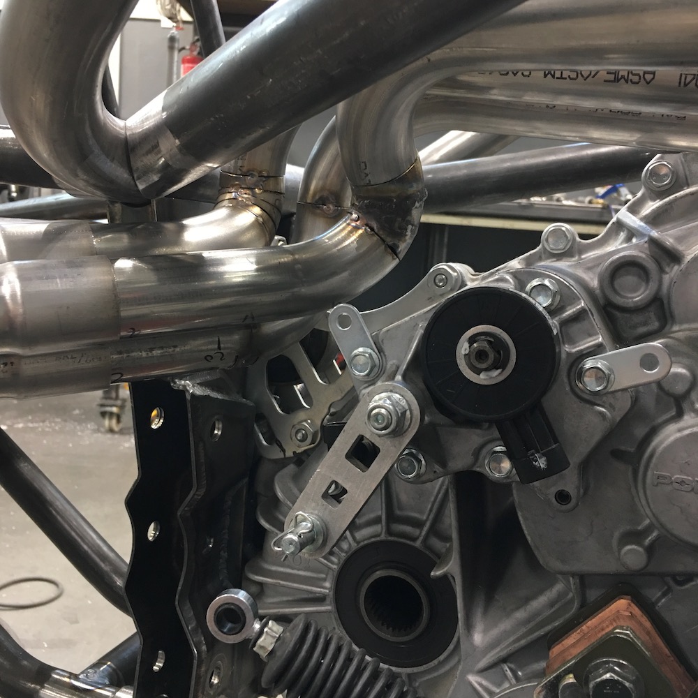
And now the Alternator. Been trying to figure out where it's gonna land. I wanted to pull away from the supercharger belt direction but alas, not happening. Fortunately the crank end is very well supported so I adapted the drive pulley to drive the alternator. I'm thinking the drive pulley may be on the large side. Originally it was going to drive off of an RPM input shaft. Phone calls are in order on Monday.

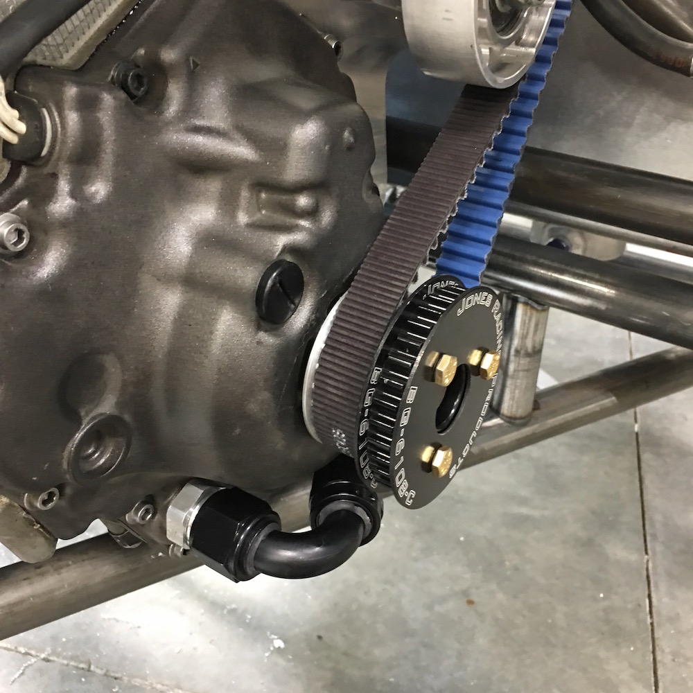
Jigged up the alternator with the belt and pulleys I have and put it up in space and then made an upper mount. Lower, adjustable mount is next.
Jan 16, 2019
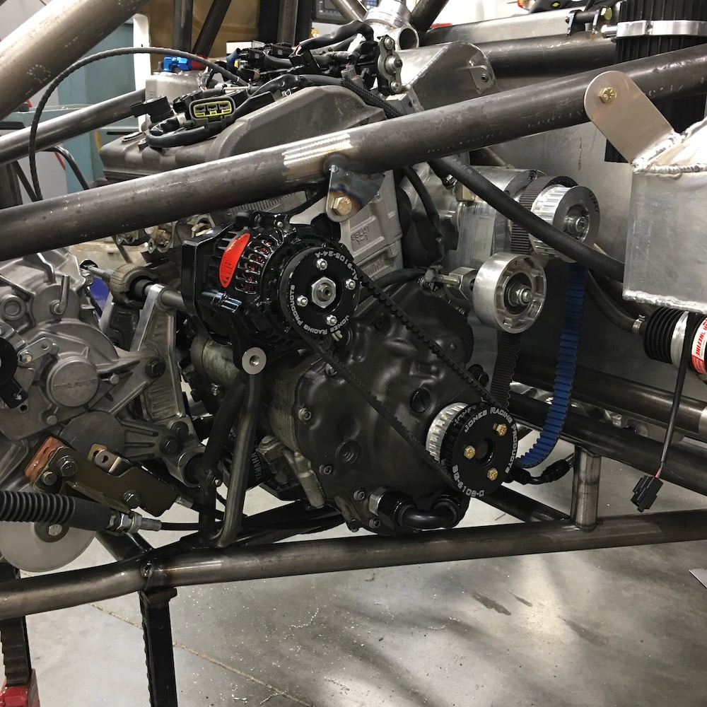
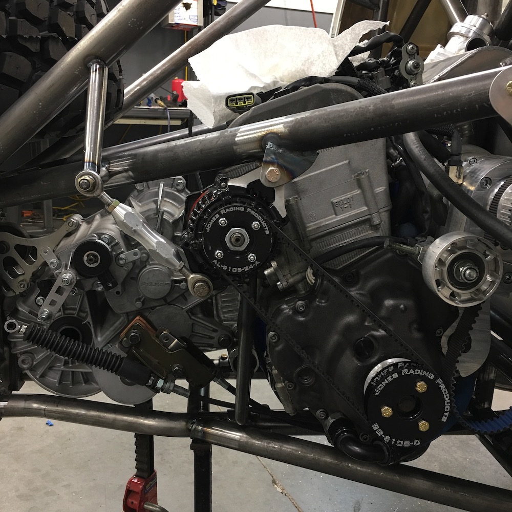
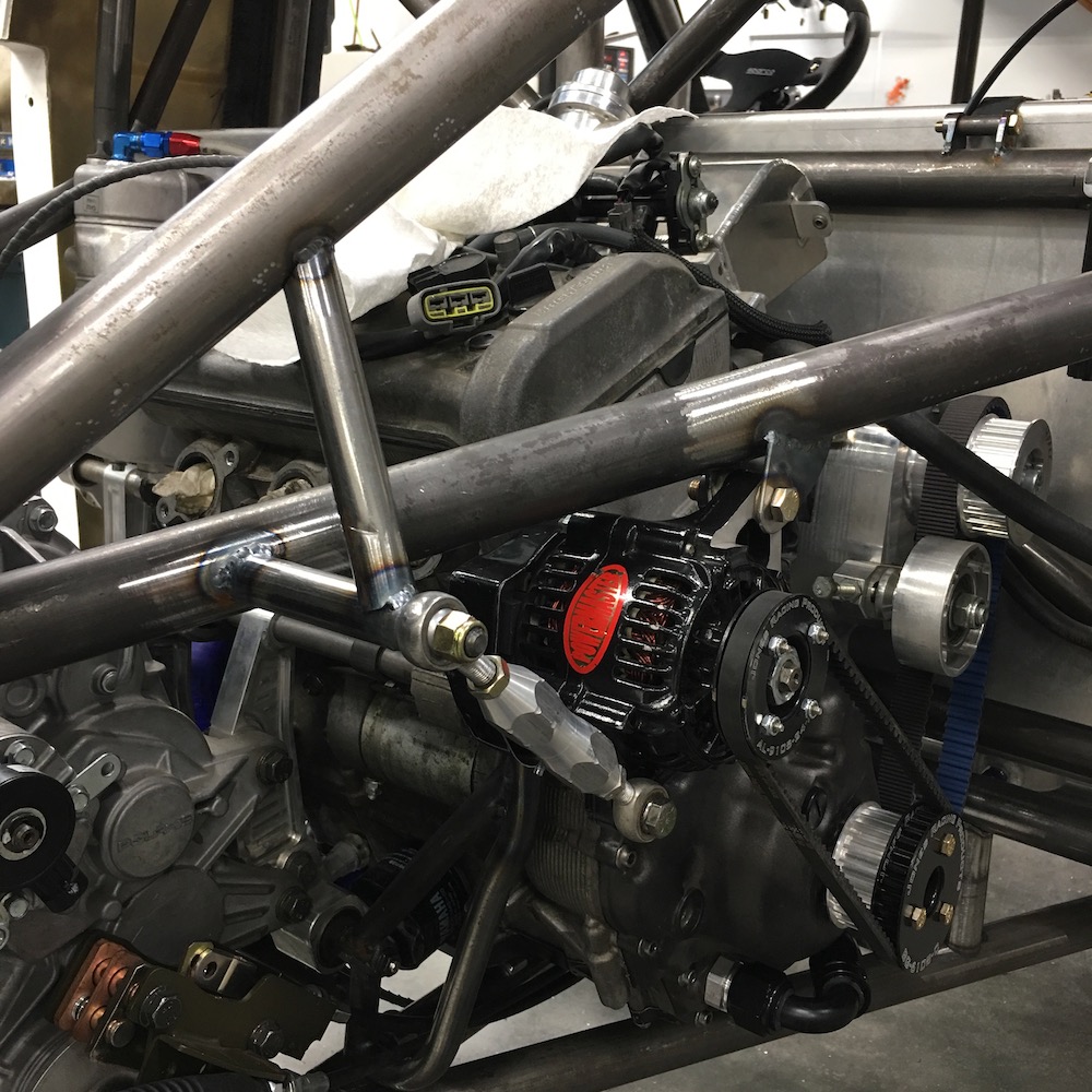
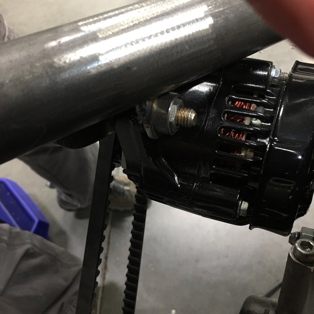
Alternator in.
Long belt and an engine that torques back, loosening the belt (better than tightening) should work - I hope.
Cogged belt should help eliminate slip if it does get “too” loose. Already thinking about tensioner design if needed.
No easy way to mount directly to the engine.
Nuuuuuut Pocket (just for Bull):
Tracking says my exhaust parts arrive today. WHOOP WHOOP!Exhaust then start on panels in the cab/rear bulkhead/center and by the time that's finished hopefully I'll have my AiM dash and peripherals and can start wire work.
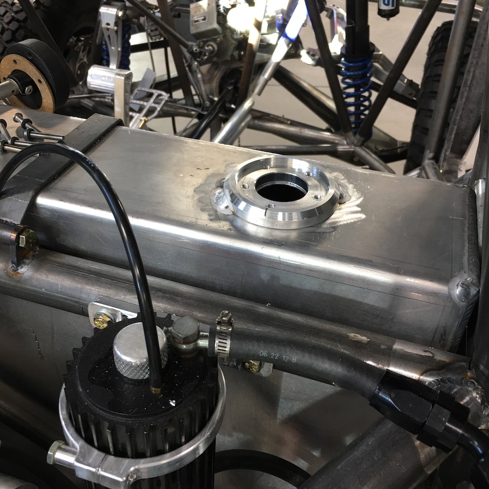
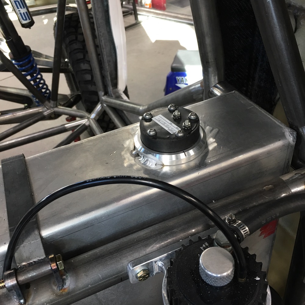
Fuel level sensor installed:
Fuel filler neck on order from Summit Racing.
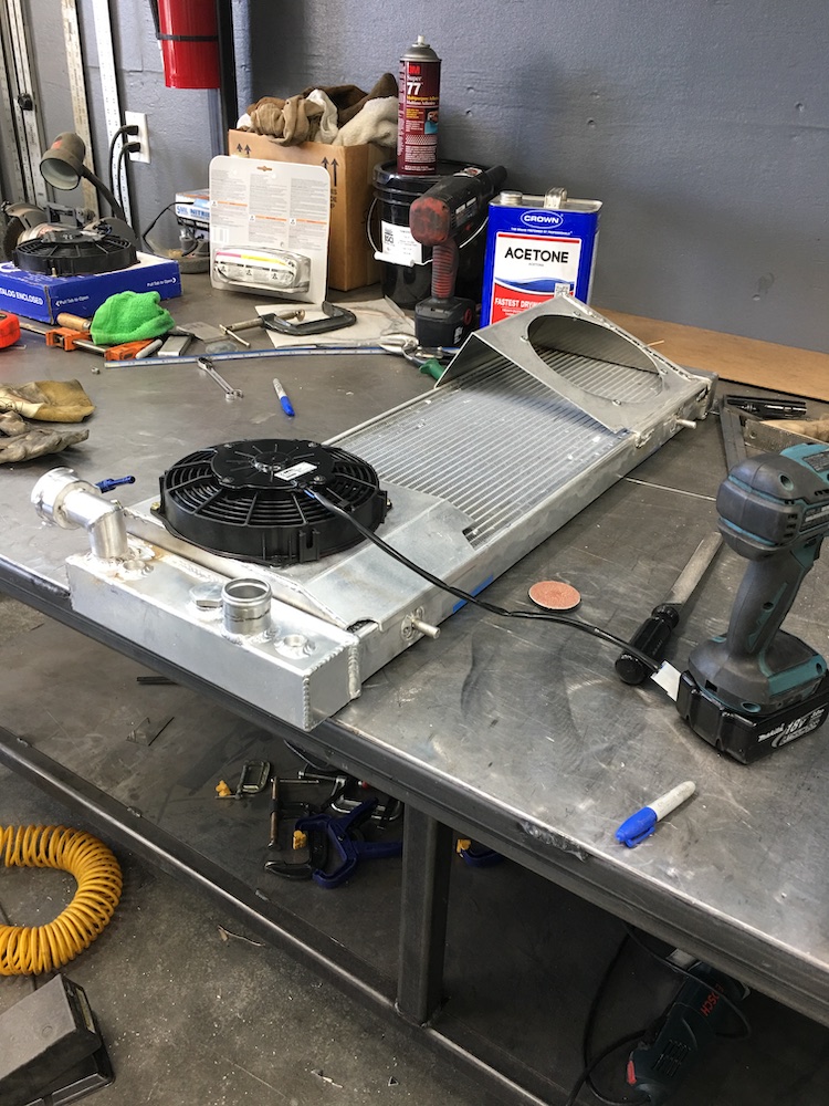
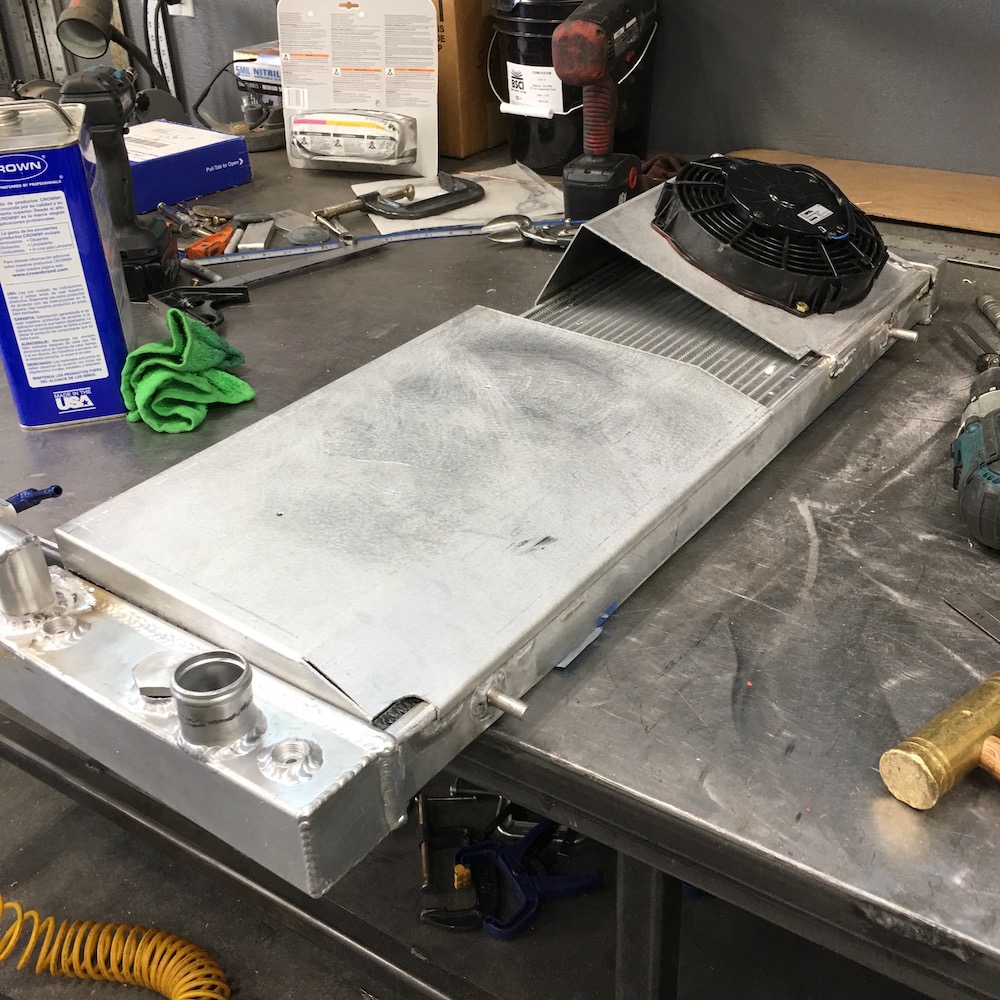
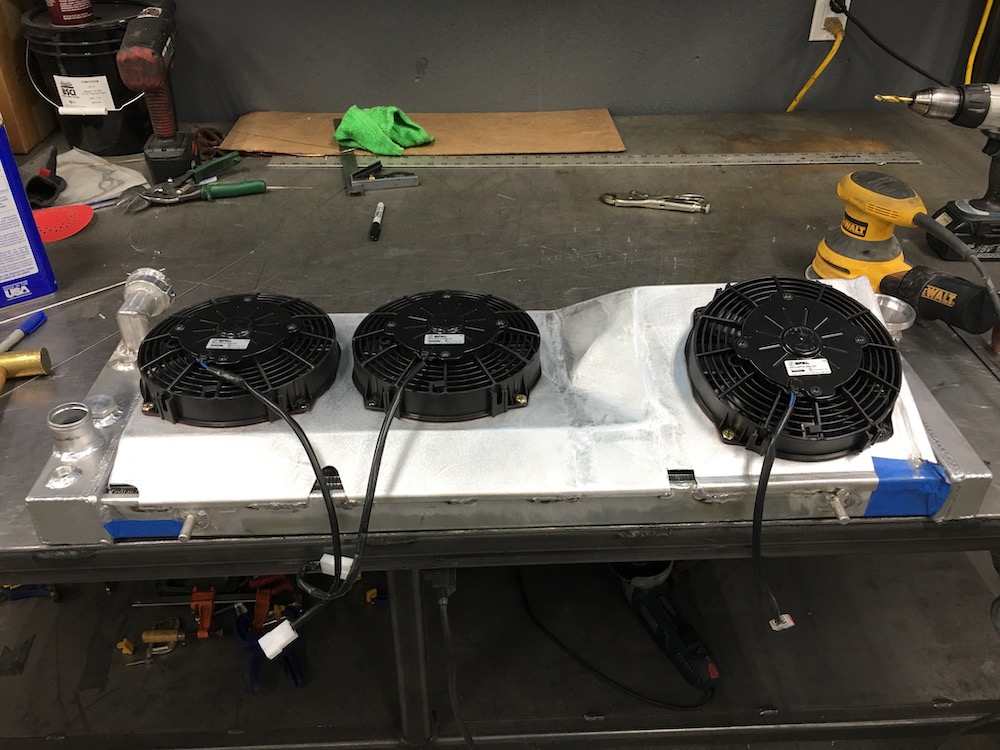
Have now moved forward to the radiator. Time to get the fans on the back of it and the shrouds in place around it.
Exhaust tooobing didn't show up yet (tracking says it's still out for delivery) so I'll keep busy up front until it does and then I'll knock out the exhaust system.v
Jan 18, 2019
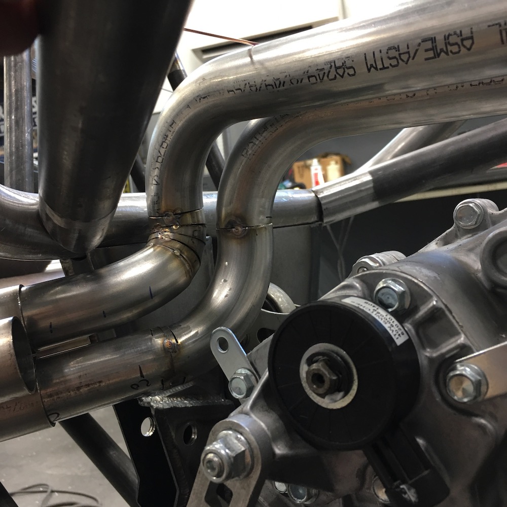
Got my toooooobing from SPD yesterday and started on the exhaust.
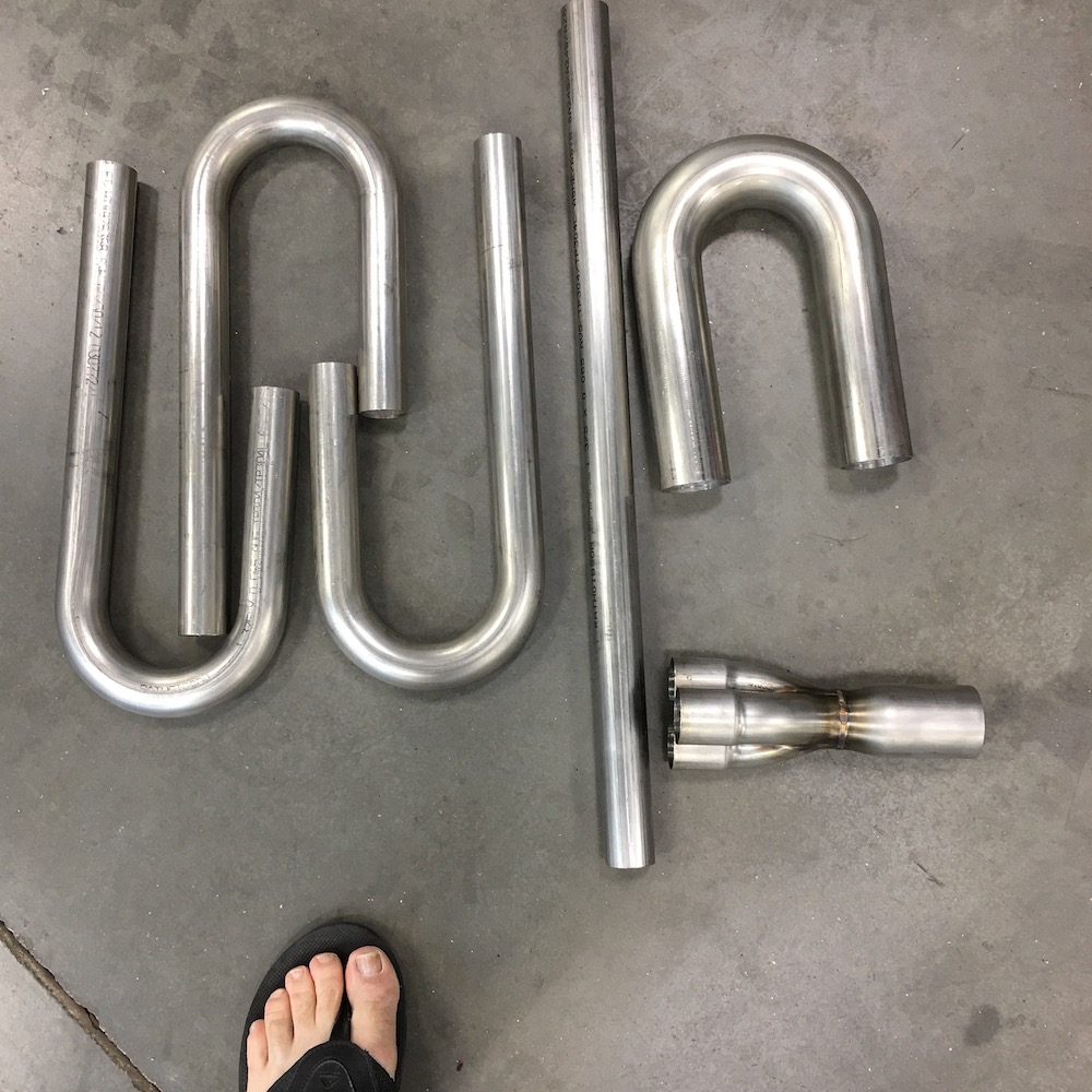
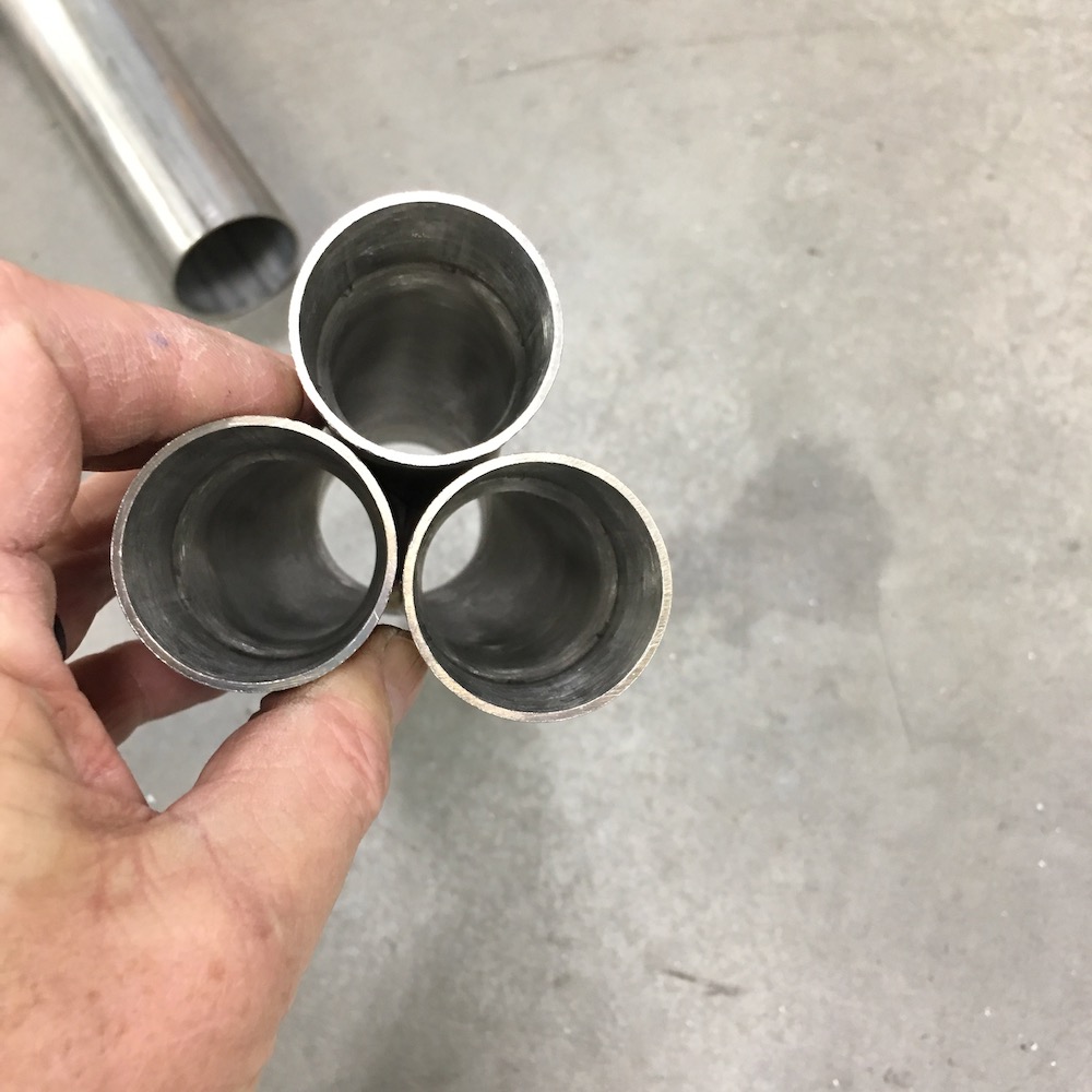
The collector is a work of art.
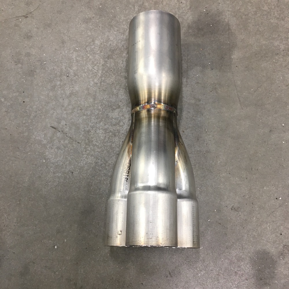
So I started cutting, bending, hacking, welding and have come up with this so far:
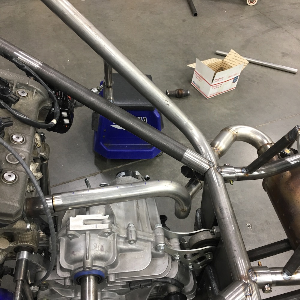
Not sure this is the layout yet. Trying to keep all three header tooooobs the same length is a bitch. I may have to cut the collector off of the 2" tube and rotate it so I can rearrange the location of the headers. I forgot how much fun this crap is - and the last two I did were two cylinder setups in the Briggs cars. This has one more that I have to deal with.
Also, don't know if you guys heard but a week after my appendectomy I get a phone call from the doctor - "You need to come in and get another CAT scan. We've lost your appendix and we need to make sure it's not still in you." - doc was kinda freaked out... I knew it wasn't in me. A week afterwards, if they'd left it in, and I'd have been one messed up camper.
Anyhow from the very start of going to the hospital I was telling everyone that was involved that I wanted my appendix in a little glass bottle with a black cap (like we had in biology) so I could set it on my desk next to my screws from my leg. Hey, it's MY appendix, I want it. They all looked at me like I had three eyes and didn't believe me. - I was serious, I wanted it. It's mine, just because you take it out doesn't mean it can't go home with me.
So the doc starts the conversation about having to come back in with "So, you know how you wanted it in a little bottle? I wish we'd done that." I go in, get my CAT scan and no, it's not there. I start telling them that it's sitting on a beach somewhere, drink in what ever an appendix uses to hold something, hat and glasses on, chilling. It either had a mid-life crisis, was tired of me beating it around or maybe it just wanted some fresh air. Regardless, it was gone.
It showed up yesterday:
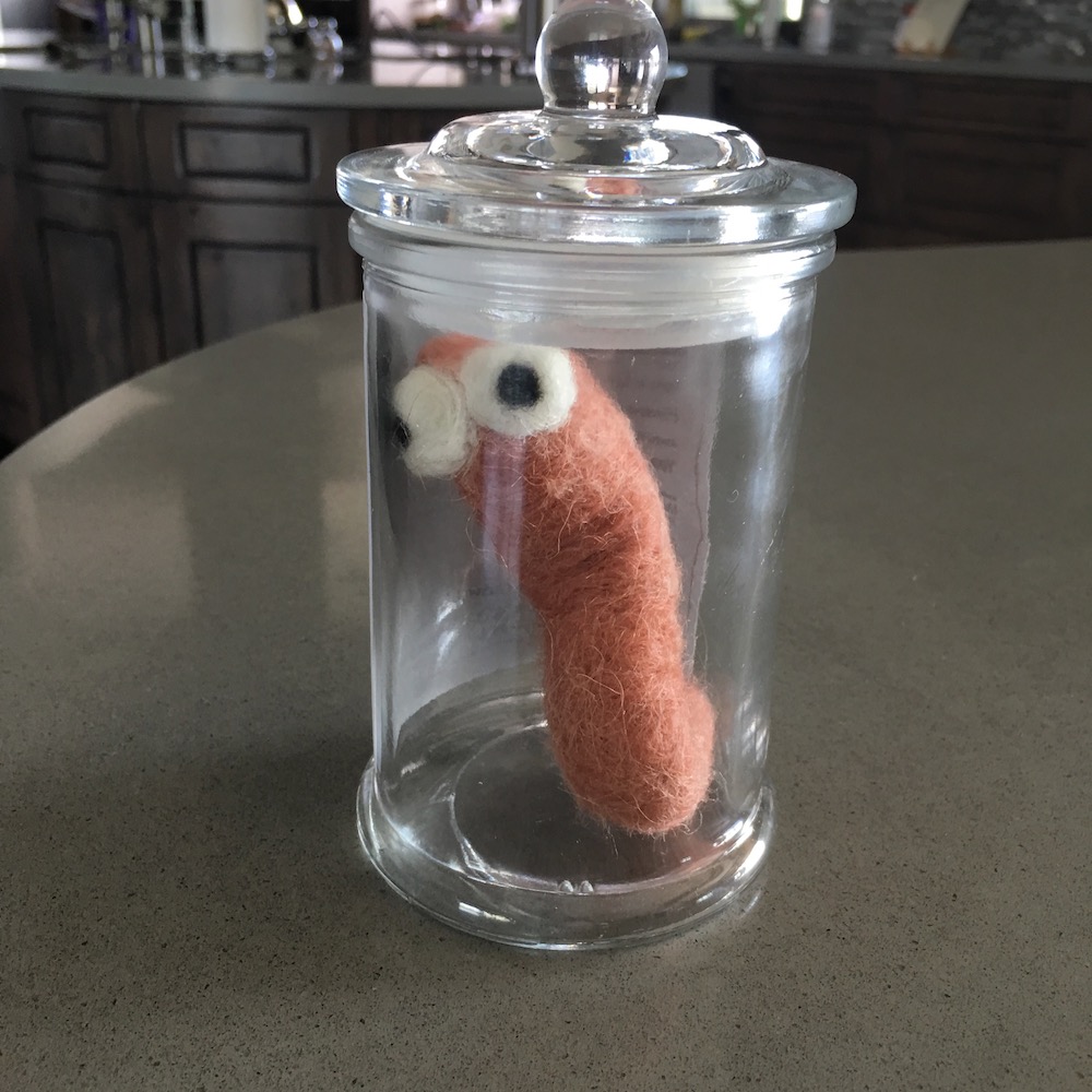
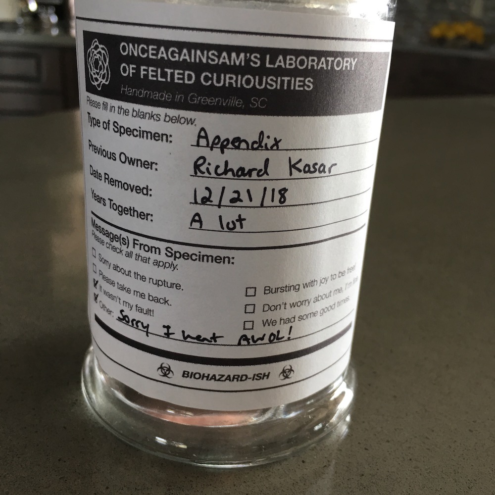
Made me laugh!
Jan 22, 2019
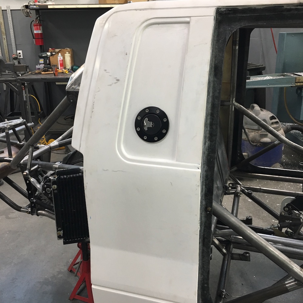
Got my fuel filler installed in the side panel. Still need to do the filler neck into the tank:
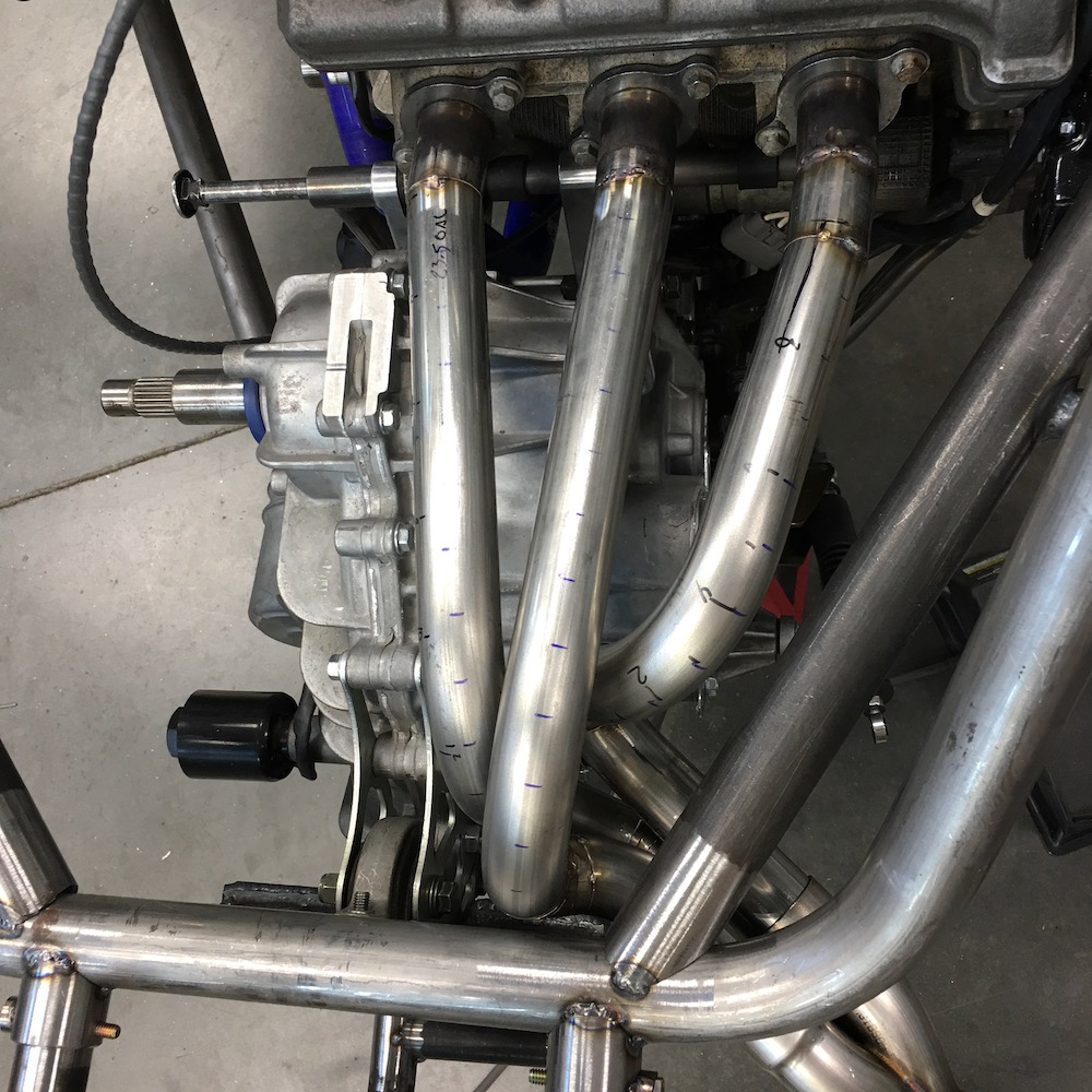
I'm pleased with the exhaust system. Measurements say all three header tubes are within .5" of each other, the longest being 23.5". I'll do a volume test tomorrow after finish welding. I'll be putting heat shielding around the exhaust and on/around some of the components. Had this planned from the beginning. The exhaust tubing will get ceramic coated too.
First tube in place:
Tube two in it's home:

bdk's non-fan process:
Clearance is good:
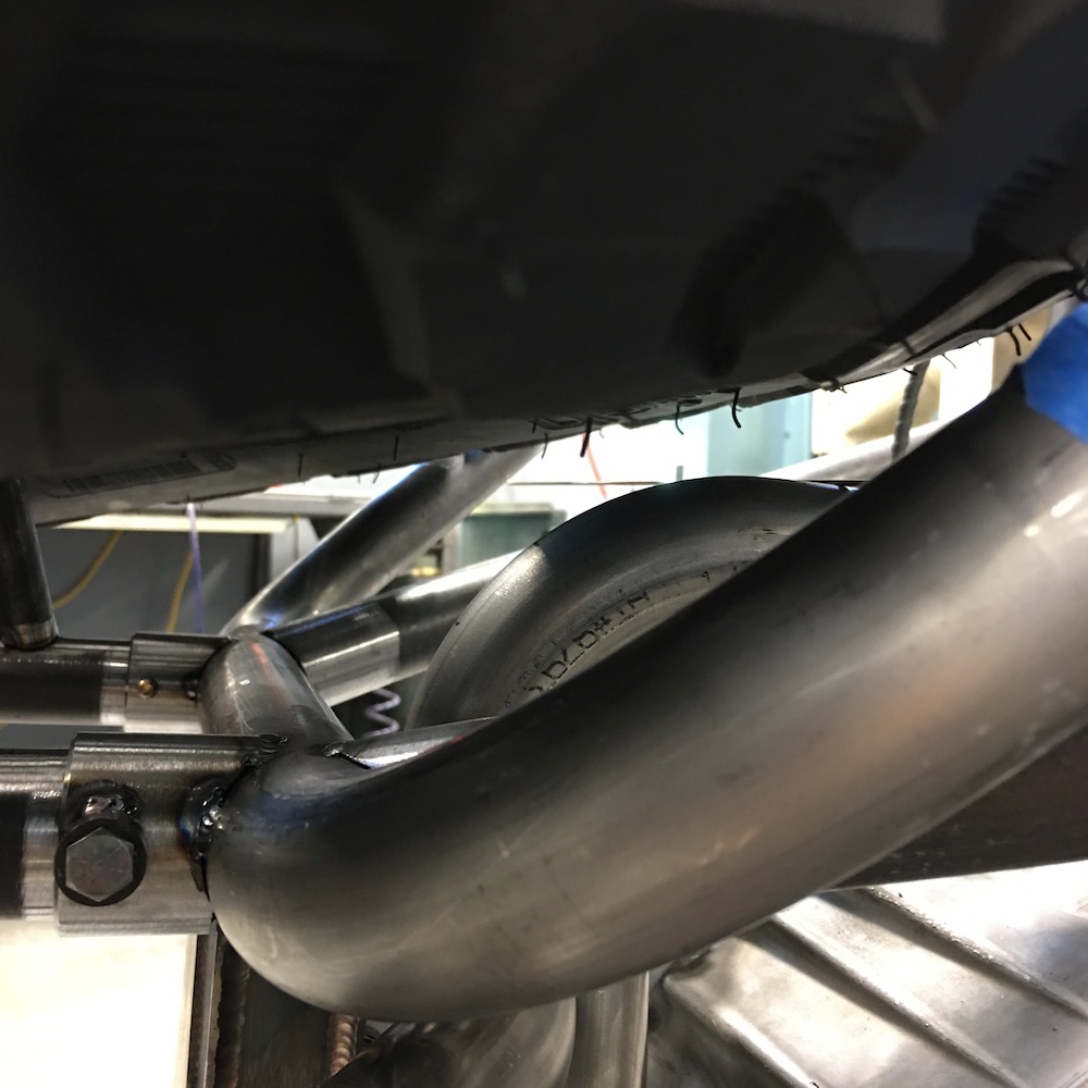
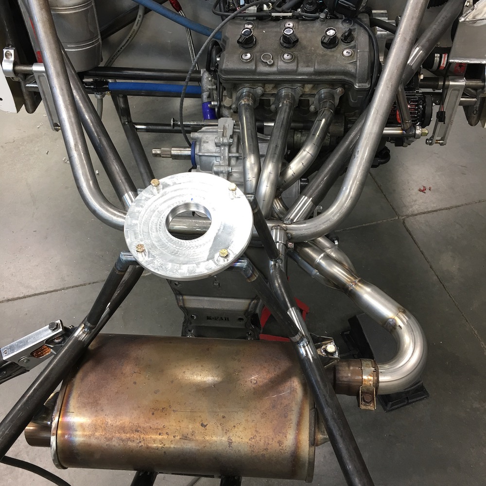
Full exhaust in place:
Jan 23, 2019
Muffler is the OEM Yamaha Nytro sled muffler so I doubt it'll be an issue. It better be quiet!!!
I purged some, some I didn't... Got blobs that are hard as hell, as you've pointed out. Overall it came out well, though and the exhaust system is finished (I may need to install a Lambda sensor yet - need to go look at wiring).
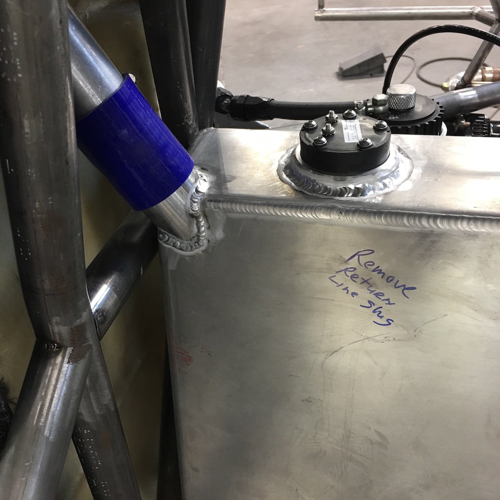
The fuel tank is finished too. Got the return line bung, fuel level sender mount and the fuel filler neck all installed and welded fully.
Made a plastic sleeve that held the hold saw in plane with the filler neck inlet tube then used a bunch of long extensions and cut away. It worked beautifully:
Pay no attention to the signage - I need to clean that off. Inside of the tank is completely clean and void of any aluminum dust/chips/parts.
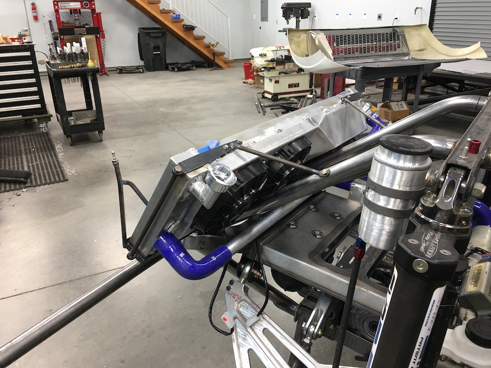
Up next I'll move to the front of the Raptor and start working on finishing the radiator - shrouding around it that attaches to the hood and the fans behind it need to be installed.
Each day another step done.
This thing may actually get fired up in the next couple of weeks.
Jan 24, 2019
The mess got to me today... spent two and half hours cleaning the place and putting stuff away and still have a mill and lathe that need attending.
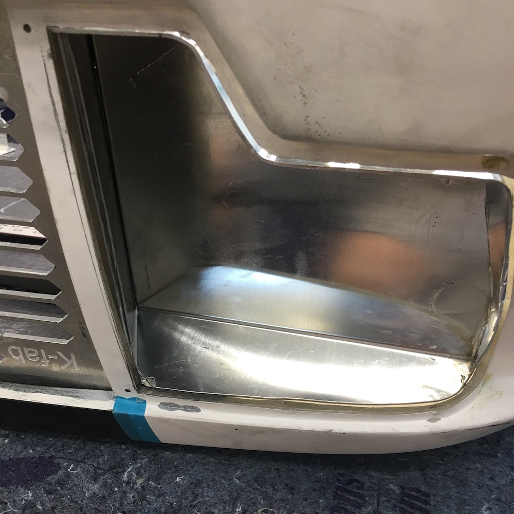
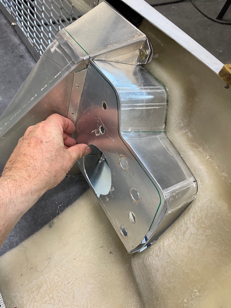
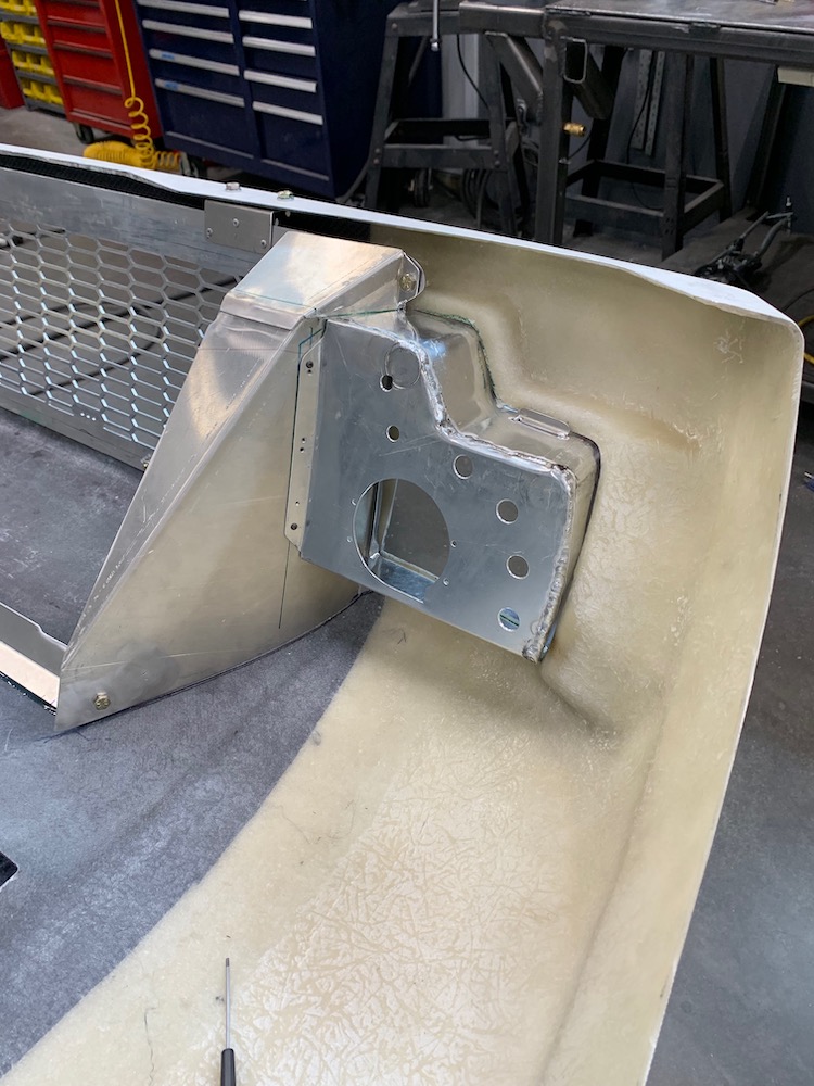
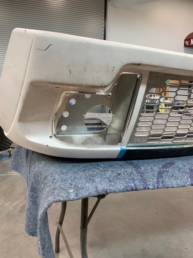
But before it did, I got some machining done. Winch will route through the front bumper tube:
There's some metal massaging that needs to happen. It'll fit flush with the tube when done.
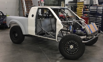
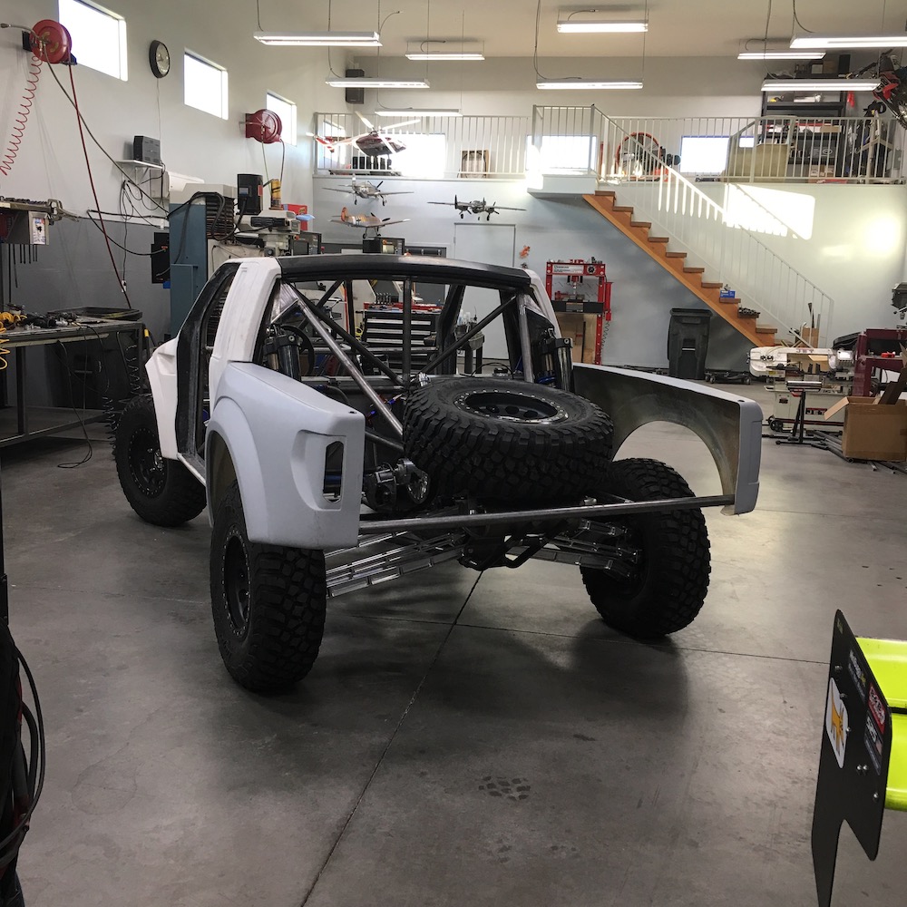
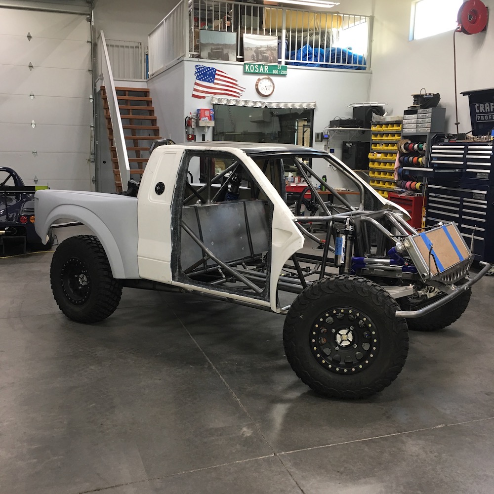
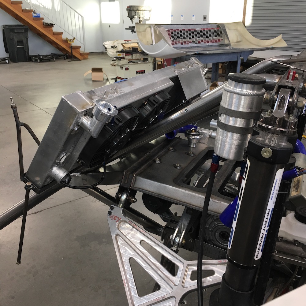
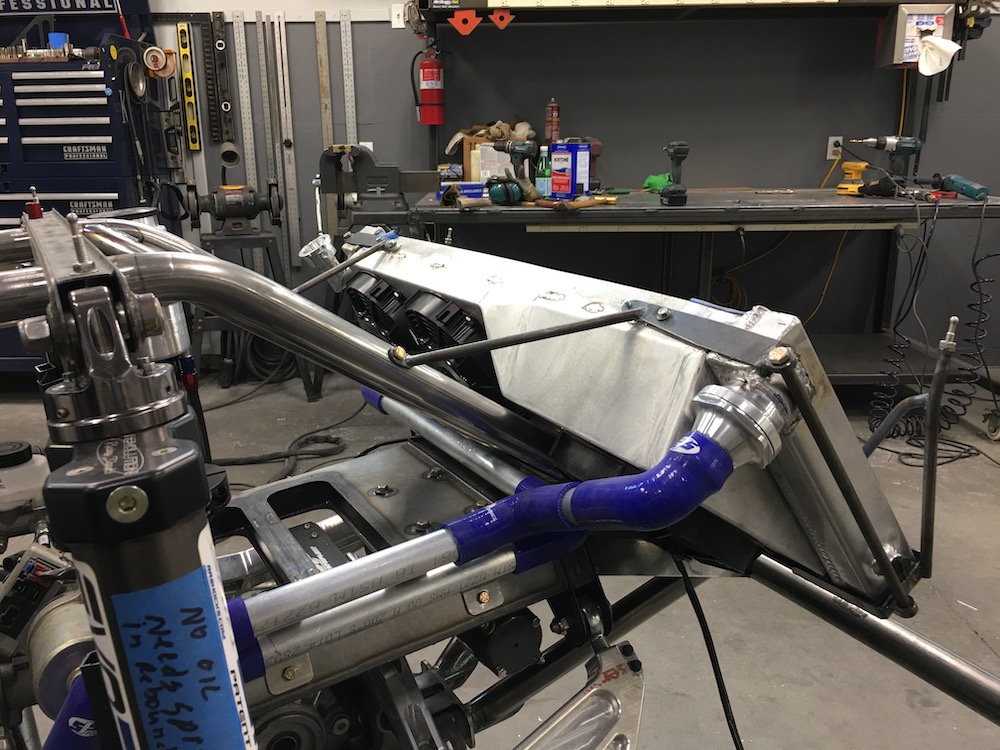
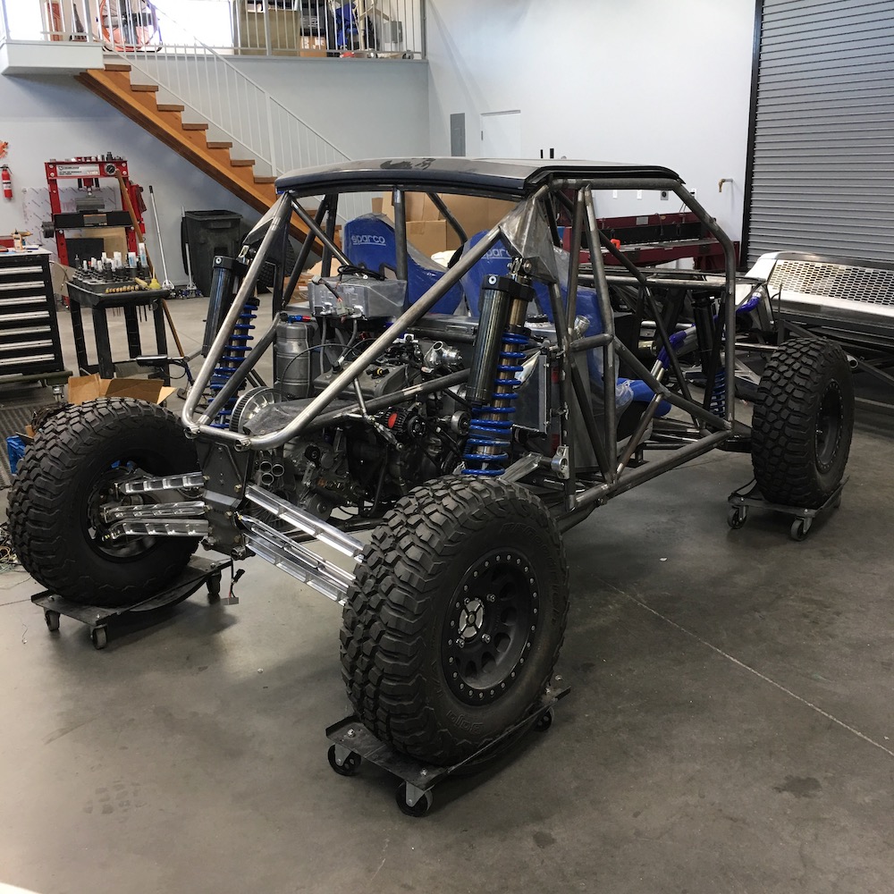
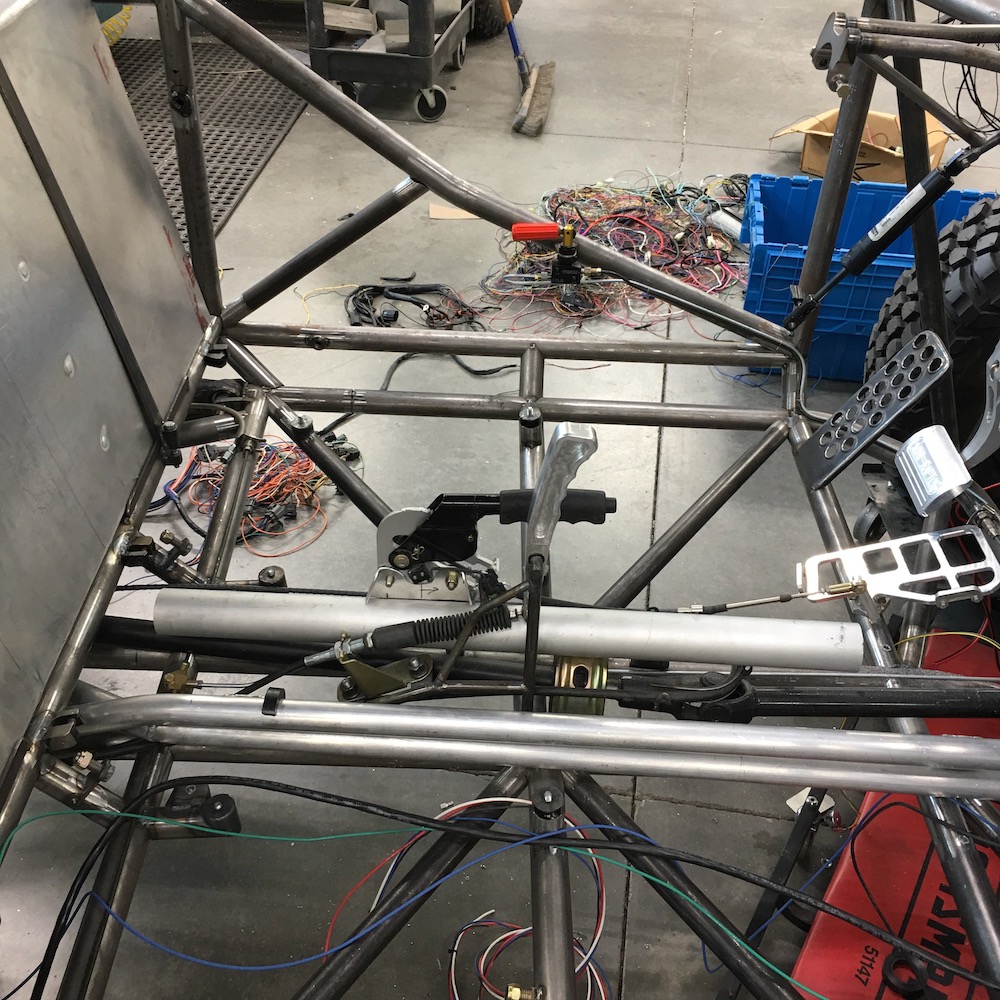
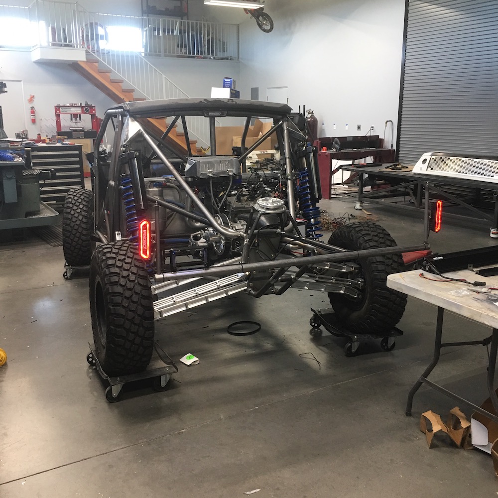
Before I started making chips I put the MR back together and made it a roller again. I need all the stuff in place so I can start making the shrouds and panels and stuff.
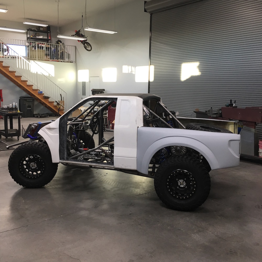
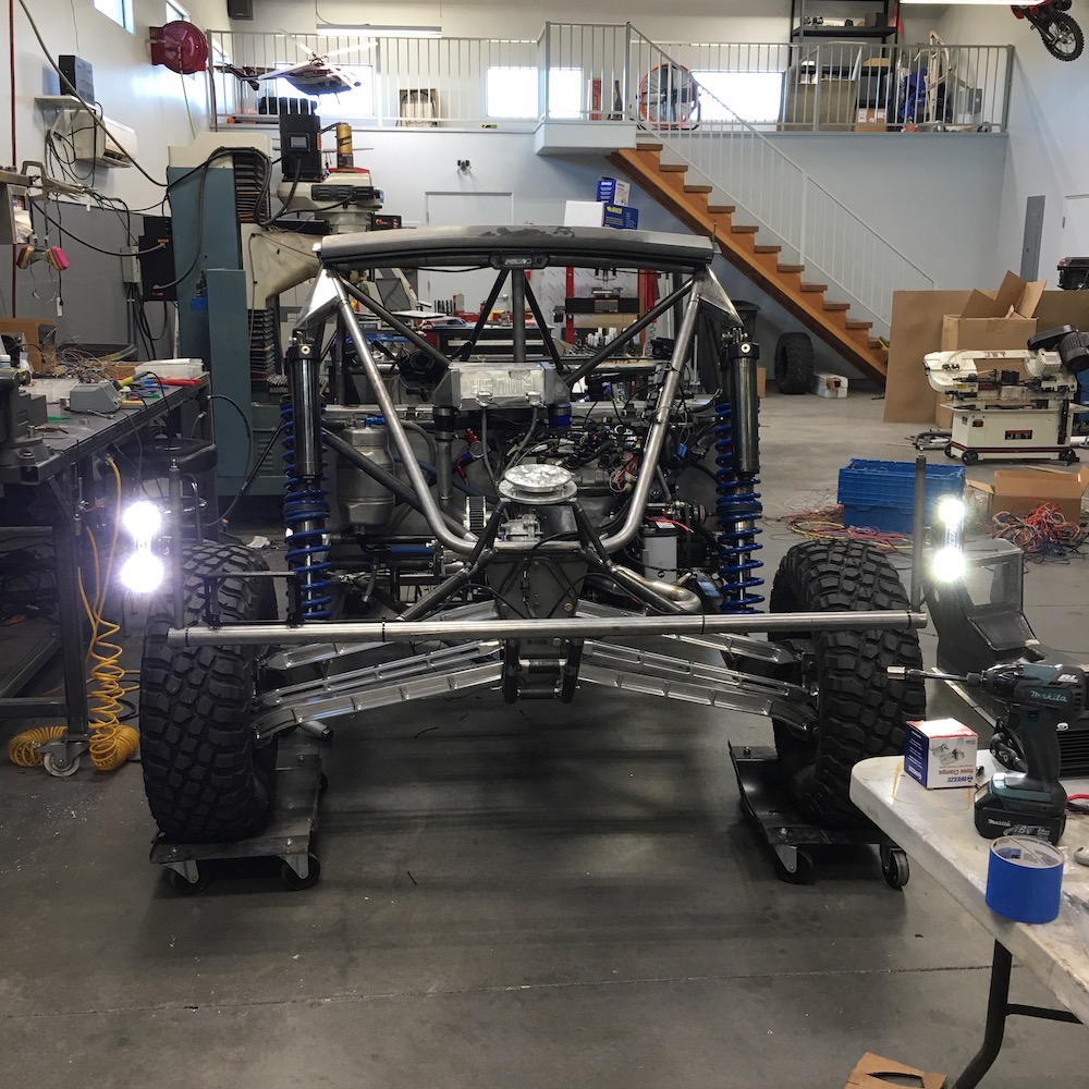
MINI-RAPTOR!
Jan 31, 2019
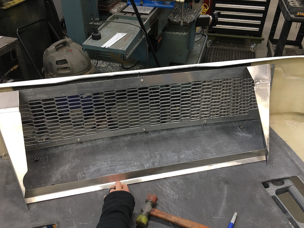
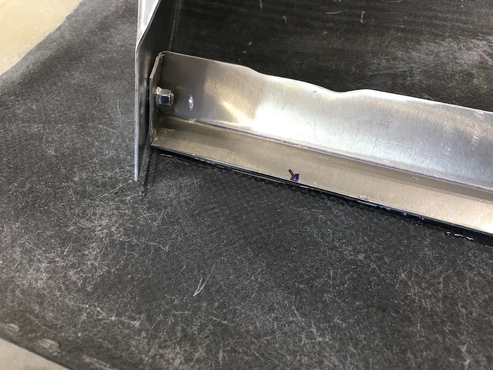
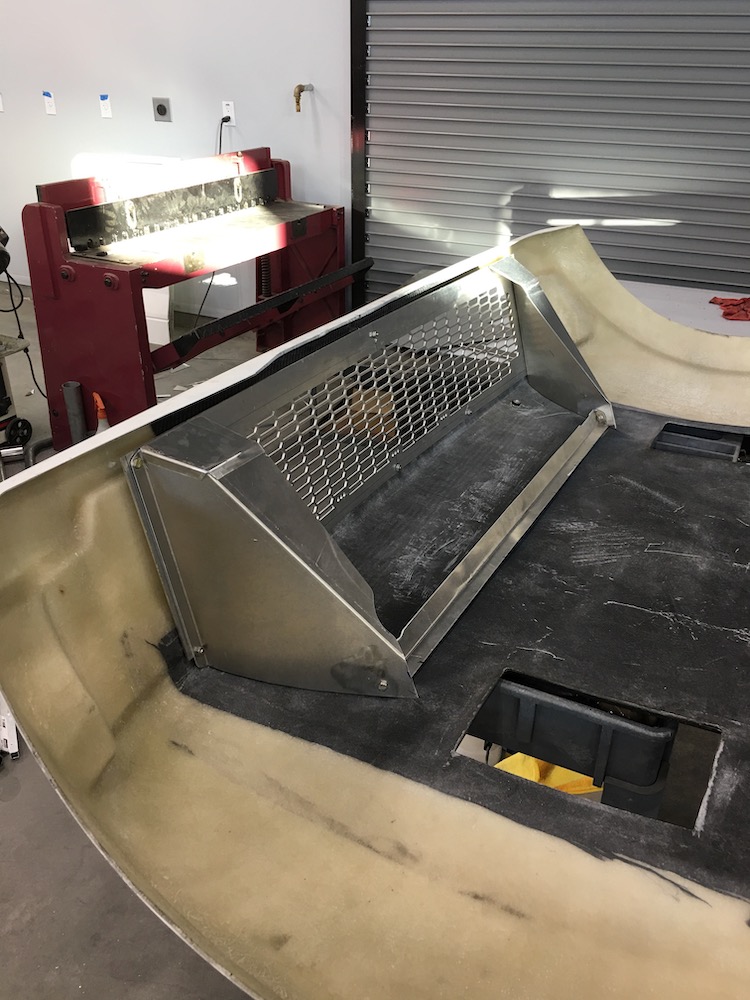
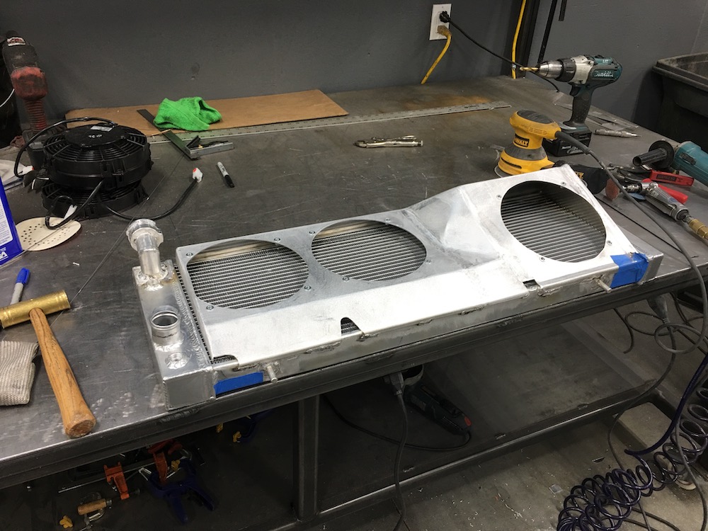
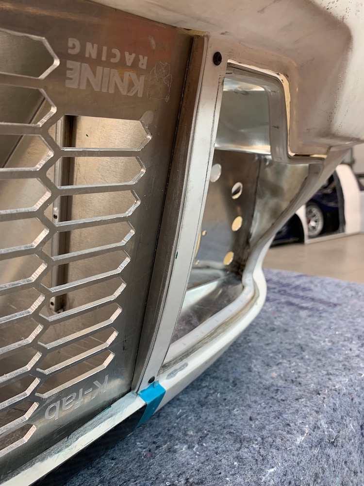
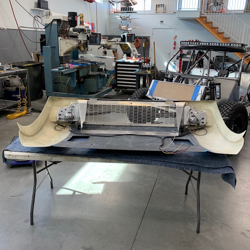
Radiator shrouds installed.
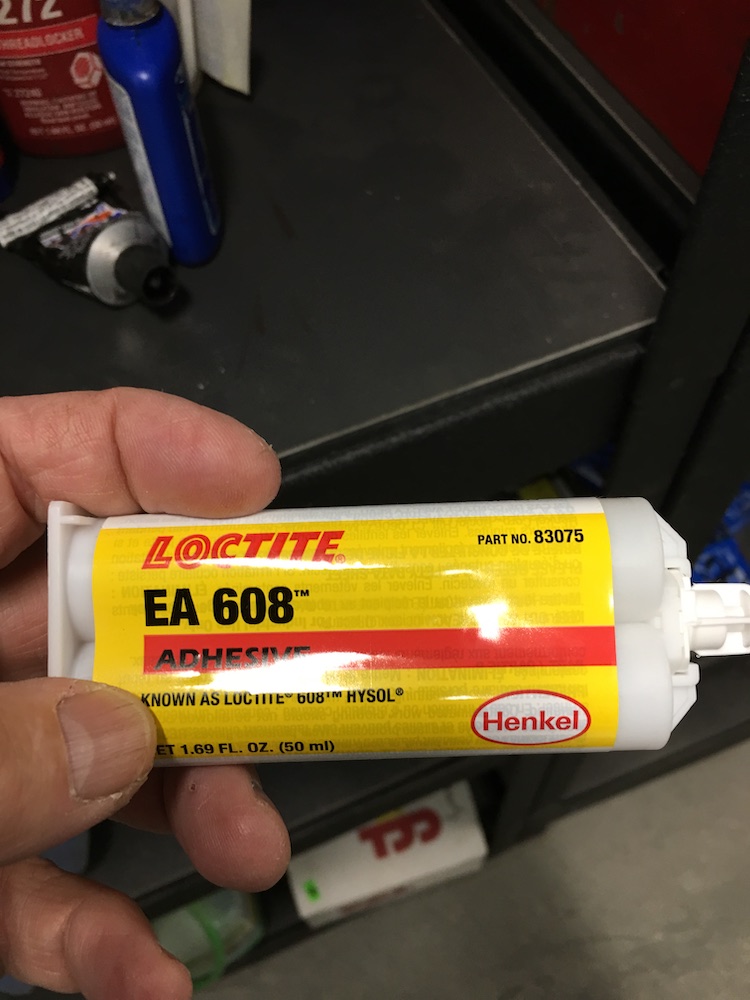
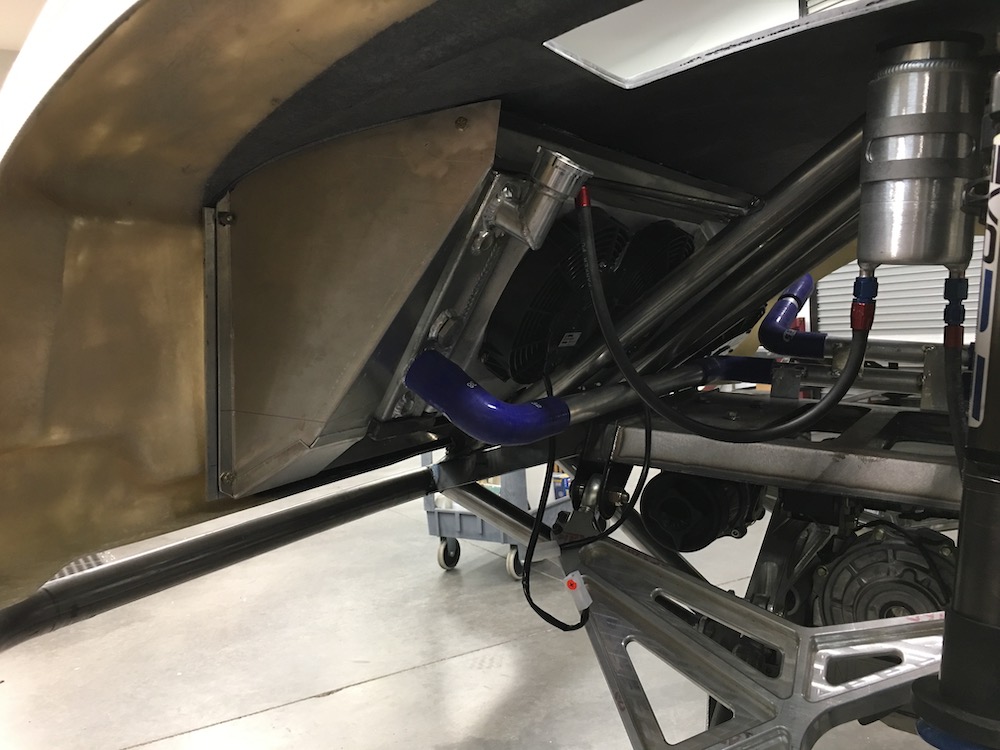
The strip that goes across the hood seals the top of the radiator. flyerrider shared an aerospace epoxy that sticks aluminum to composites. Sticks it really well.
Strip goes here:
Use this:
End up with this:
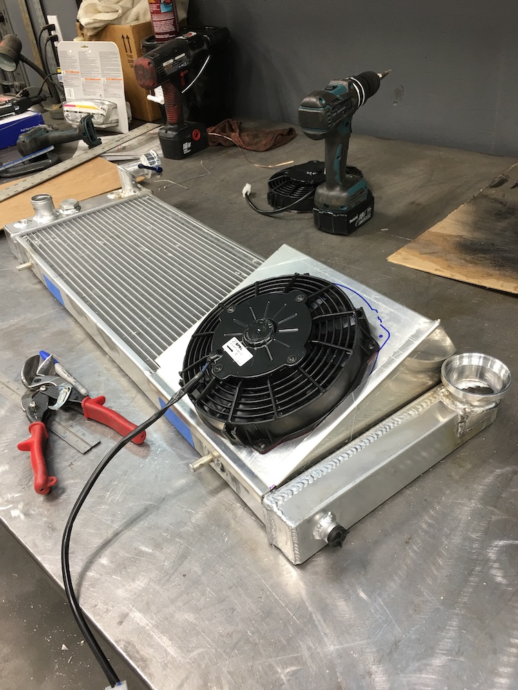
This fan goes here:
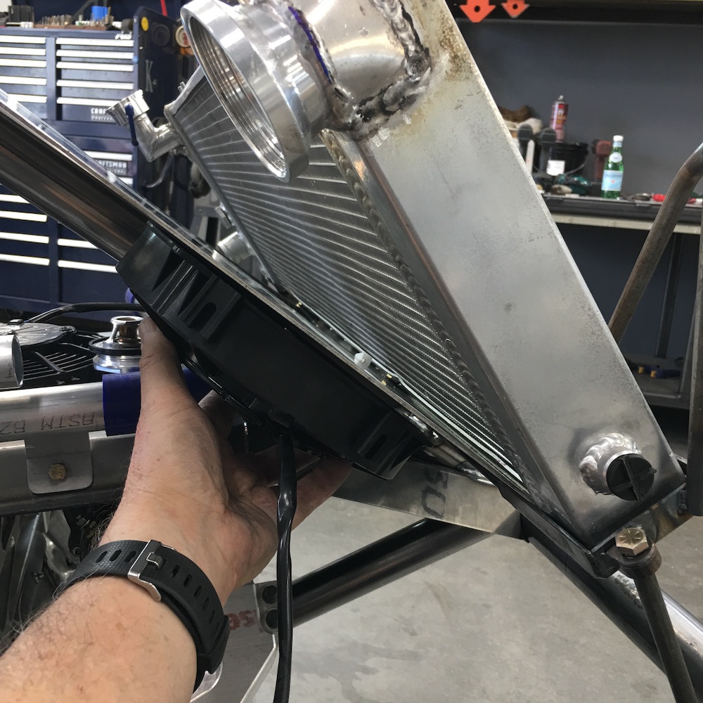
Like this:
Feb 4, 2020
So fan #2 is going to fit on the other end:
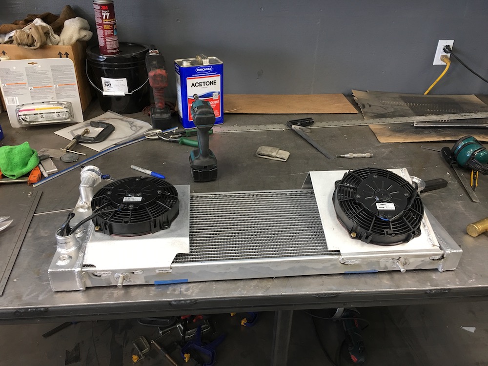
And then I discover that the middle fan is on the same exact plane as fan #2 - so in typical Mini-Raptor fashion, I fabricate a second piece - one that holds both fans.
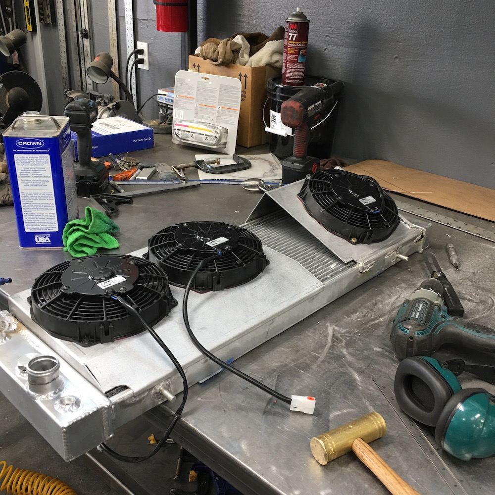
And today I filled in the gap between the two fan shrouds:
Oh, my dash came in too (insert cave man noises - been making them all day and while I was programming it yesterday).
Feb 7, 2020
It's now all about heat control I wanna keep it OUT. The RZR cooks our feet and plastic is a better insulator than aluminum sheeting.
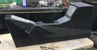
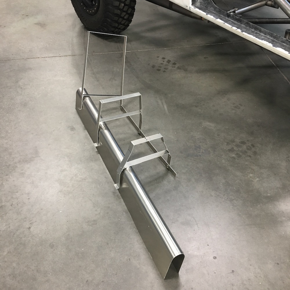
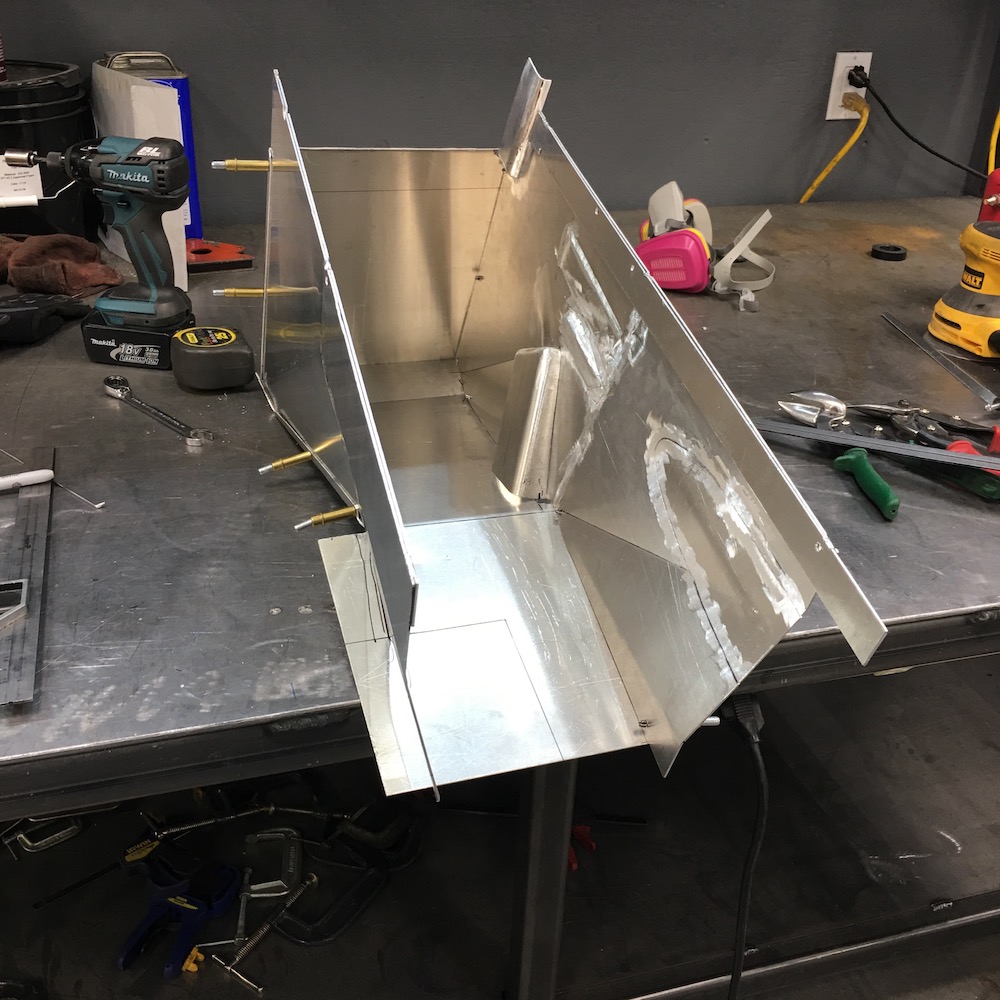
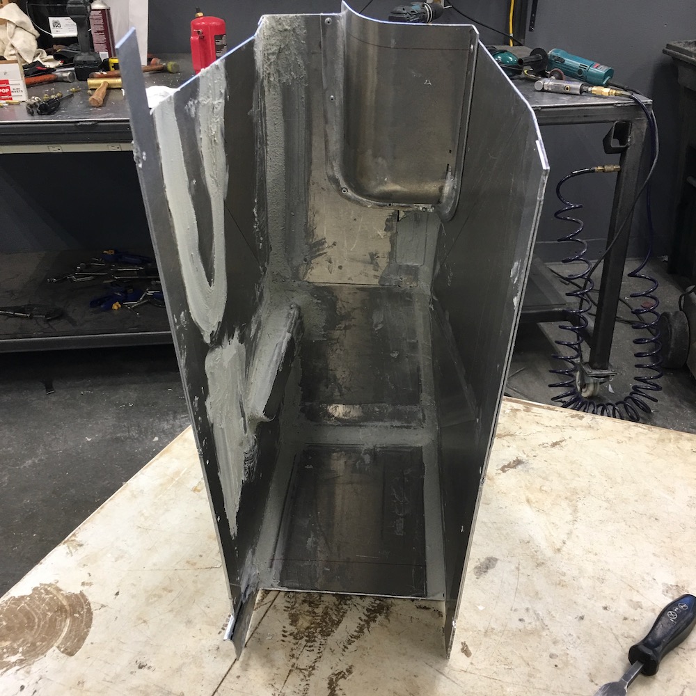
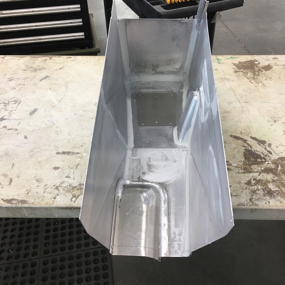
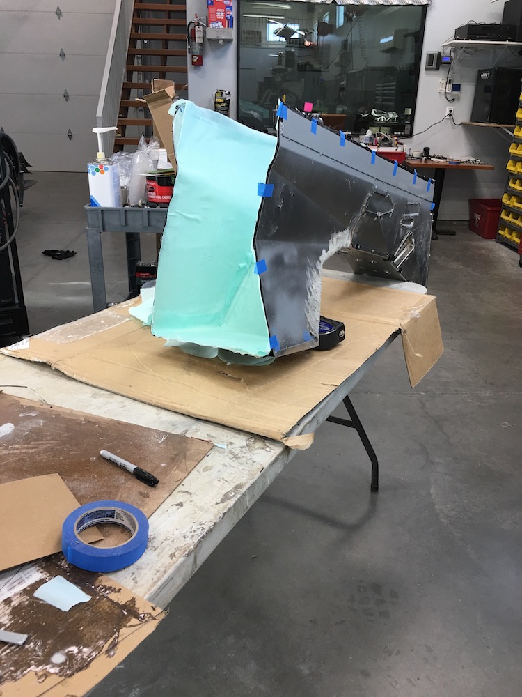
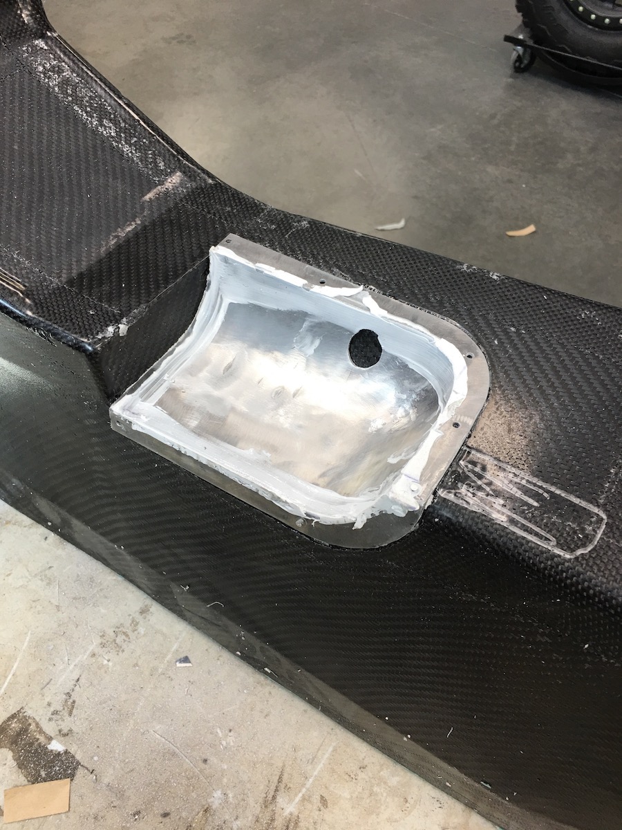
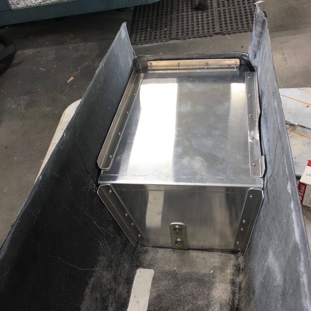
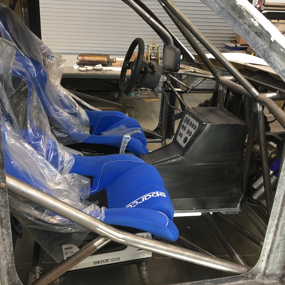
Started on the console concept.
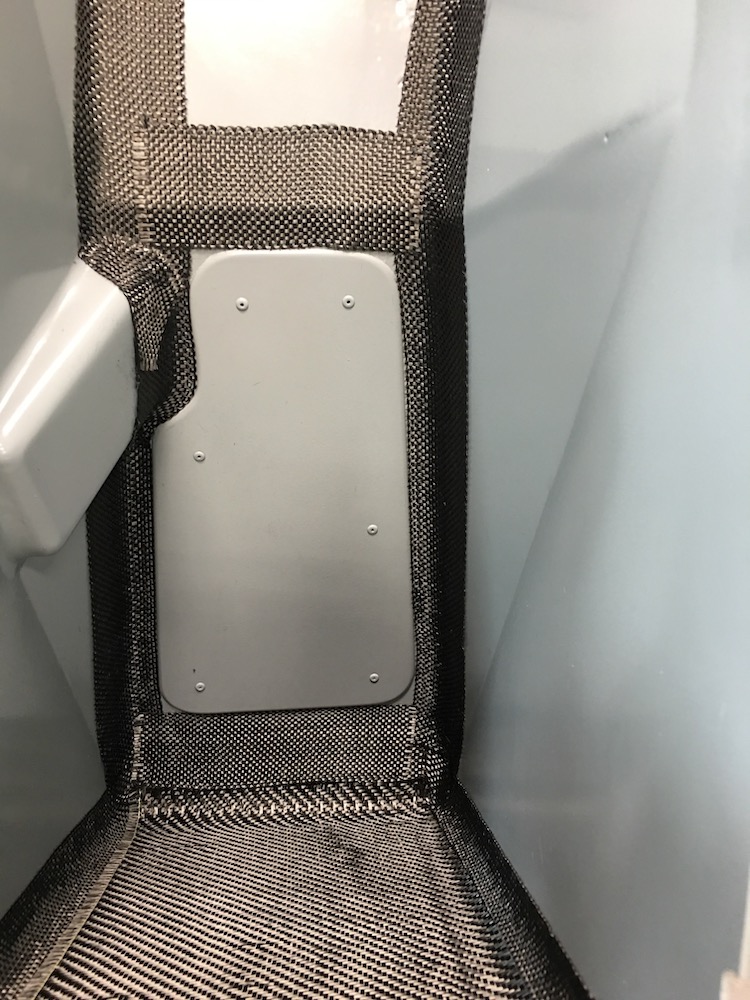
It'll be sheet aluminum and probably covered with carbon fiber, because, well, I like it. I've ended up with a really large storage compartment between the seats. WHOO HOO!!!
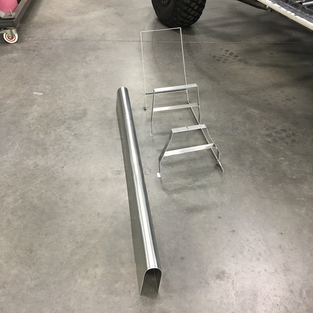
The U goes over the water lines and it'll be getting a layer of insulation stuck inside of it.
The console will then go over the U.
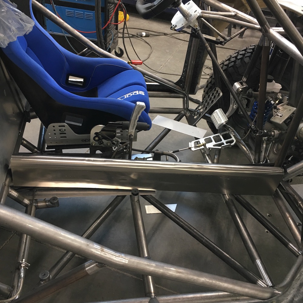
Feb 10, 2020
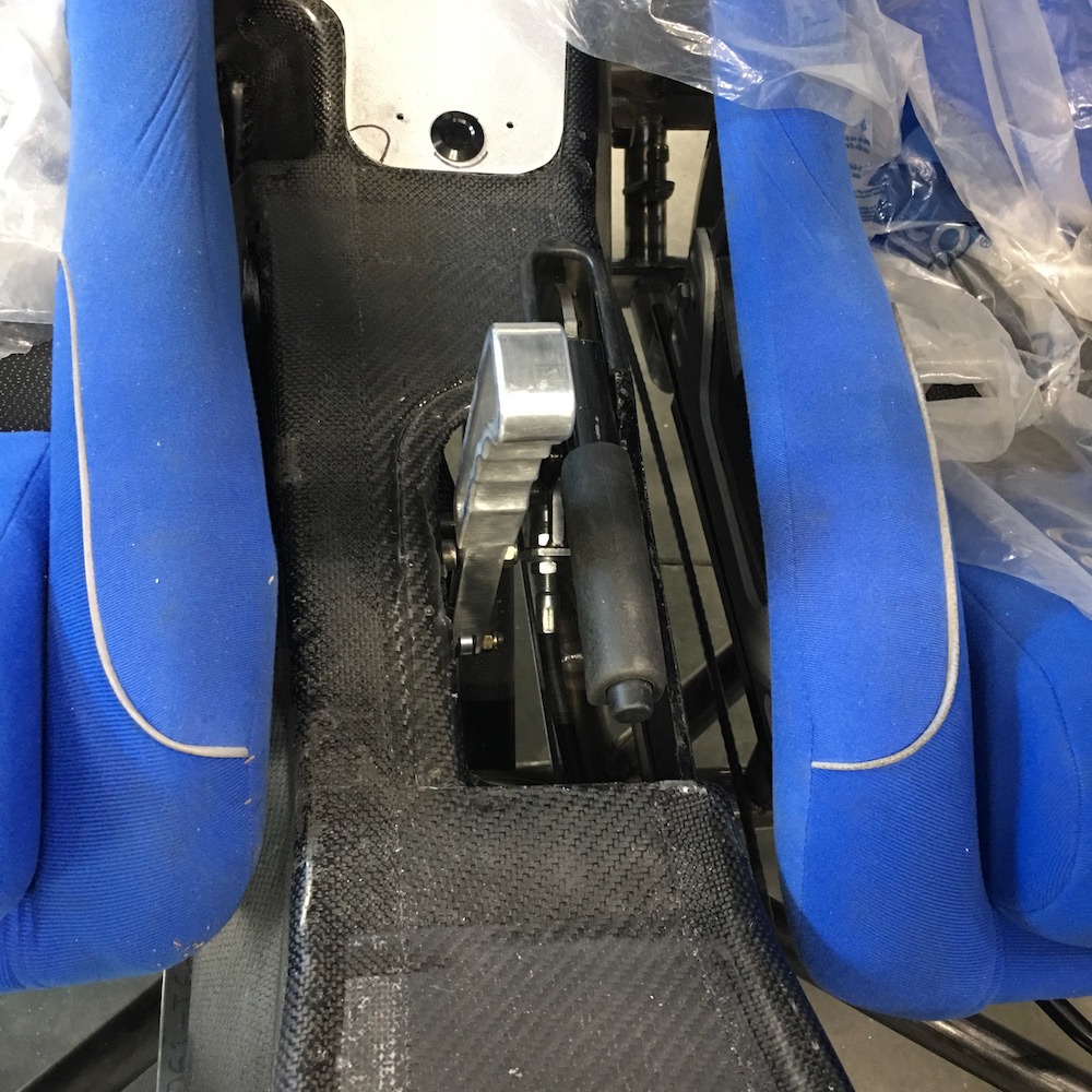
Got the heat shield trimmed and fit:
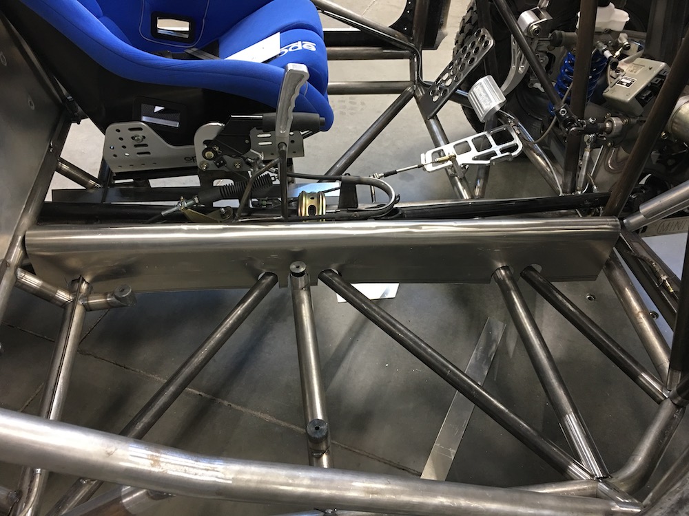
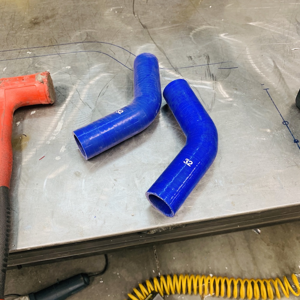
The coolant toooobing fits pretty darned well without any help:
But it still needs a bit of help centering in the U to allow for room for the heat reflective tape stuff so I made a couple of donuts that center the toooobing in the cover:
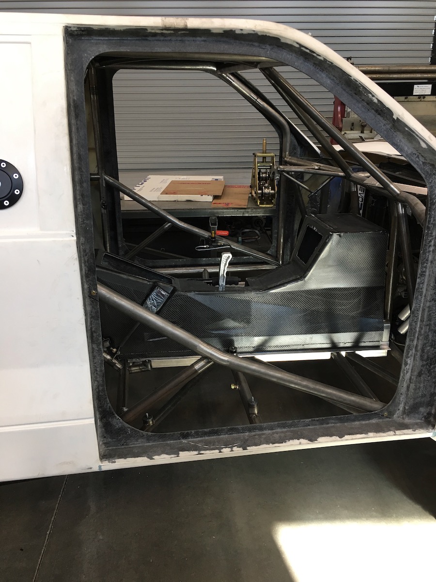
The center console is reeeeaaaallllly close to the passenger seat - there's some tweaking that will take place as it develops.
Feb 13, 2020
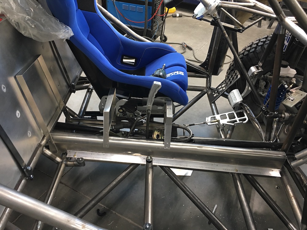
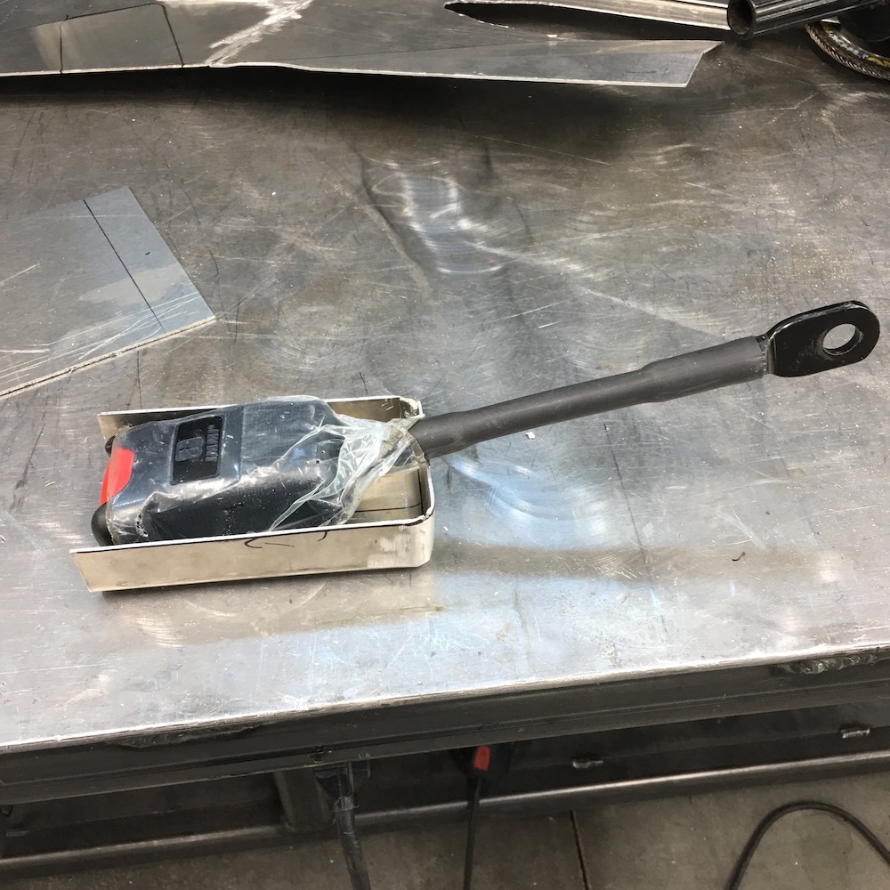
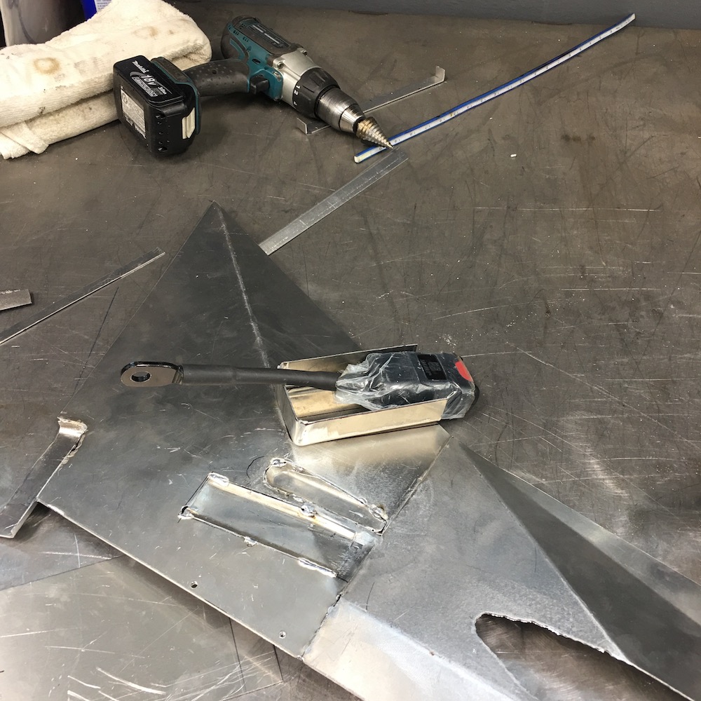
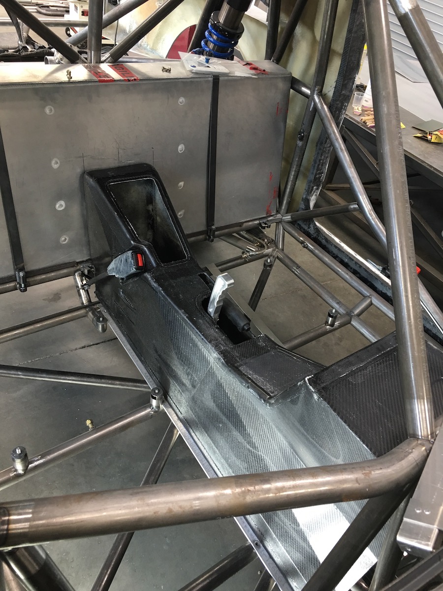
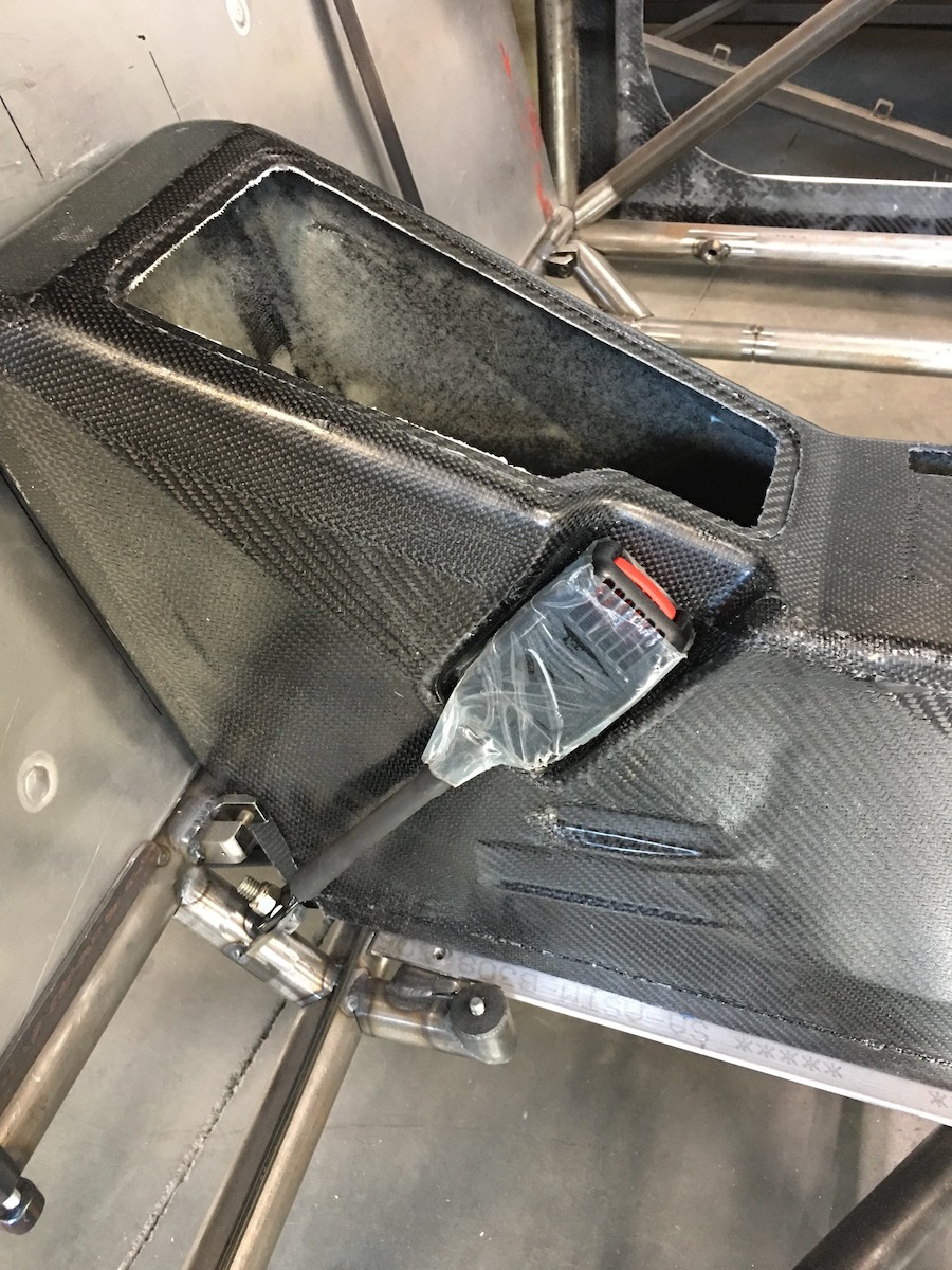
Yesterday I knocked out the back half of the molds for the center console then realized I haven't put the belts in yet and I need to figure out where/how to mount them.
What makes it even more fun is that I'm running both OEM RZR seat belts (street legal) and harnesses.
So today I spent my time making threaded bungs and figuring out where stuff is going to attach. I still have to get the inner buckle's mounting place figured out. Pix tomorrow...
Feb 15, 2020
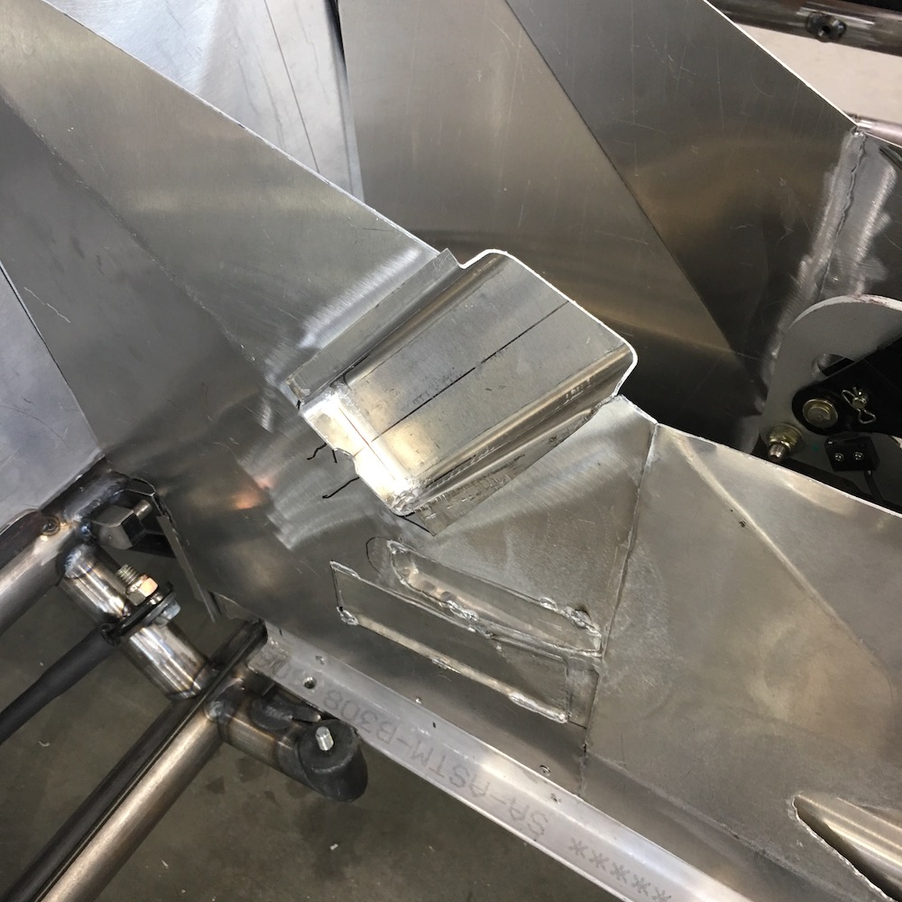
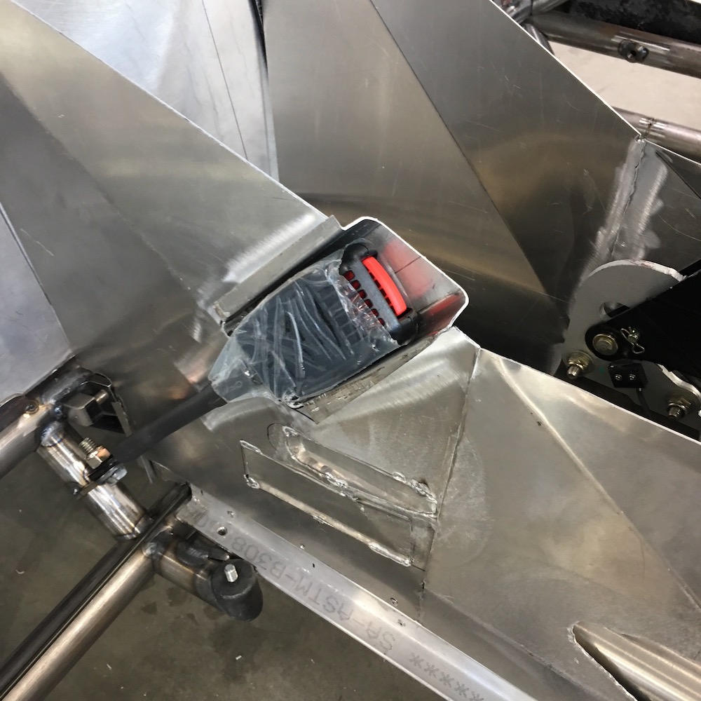
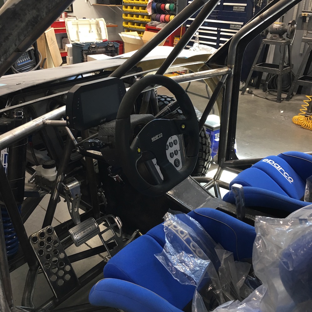
Seatbelts and harnesses are installed. There's a bit of interference between the passenger seat and the side of the console because of the water lines and I had to put belt/harness stuff in there too so I figured I'd best get them in so I can make the mods to the panels for the center stuff first.

Driver's harness and belts shown installed.
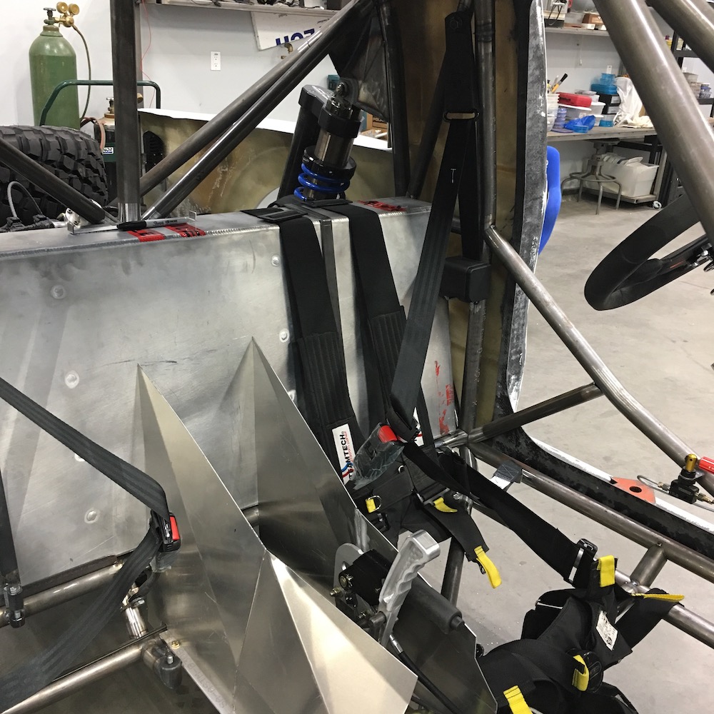

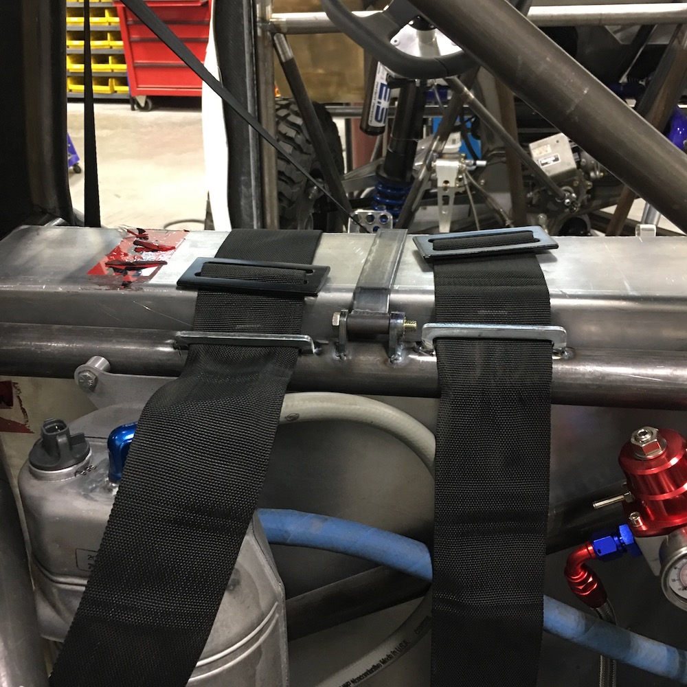
Instead of bolting the shoulder harnesses in place I went this way. Yes, the left one's back off line a bit - if it wasn't the bolt holding the tank strap in place wouldn't be removable.
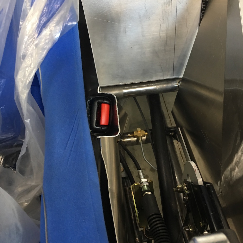
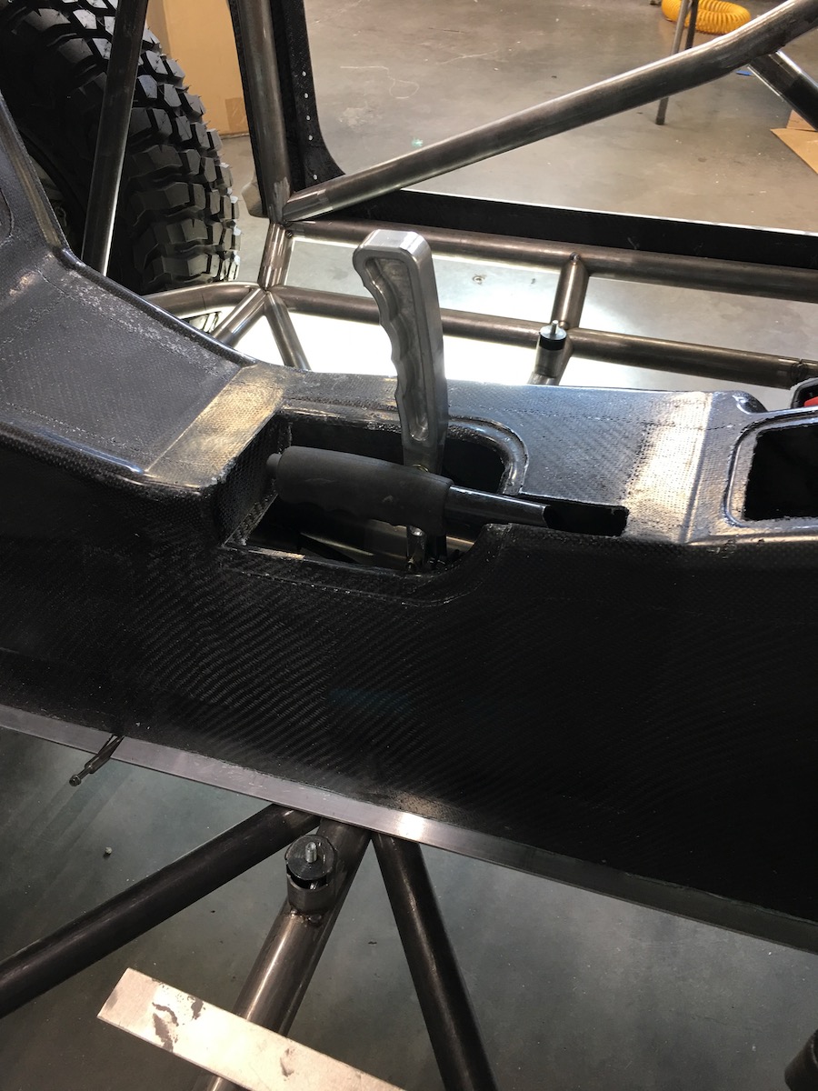
Feb 21, 2020
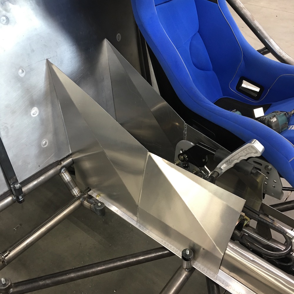
Clearance Clarence. I need clearance.
The co-dawg's side's proving to be a bitch. (and I'm probably making it harder than it needs to be.)
The seat base, a seat mounting bolt and the seat belt latch all seem to want to share space with the center console so I'm having to give each one it's own happy little relief. Argh. I'm getting good at forming sheet metal.
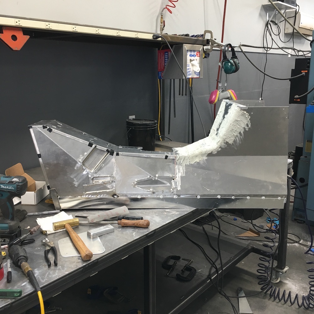
The aluminum console in the pix is actually the mould for the composite piece that will end up sitting in place. I'm working on making clearance pockets for anything that may be in the way and after getting all the little aluminum bits and pieces tack welded in place I'll Bondo the inside of the aluminum console and then sand smooth all the blends and radiuses among the panels and parts. Should make for a pretty trick piece when I'm done.
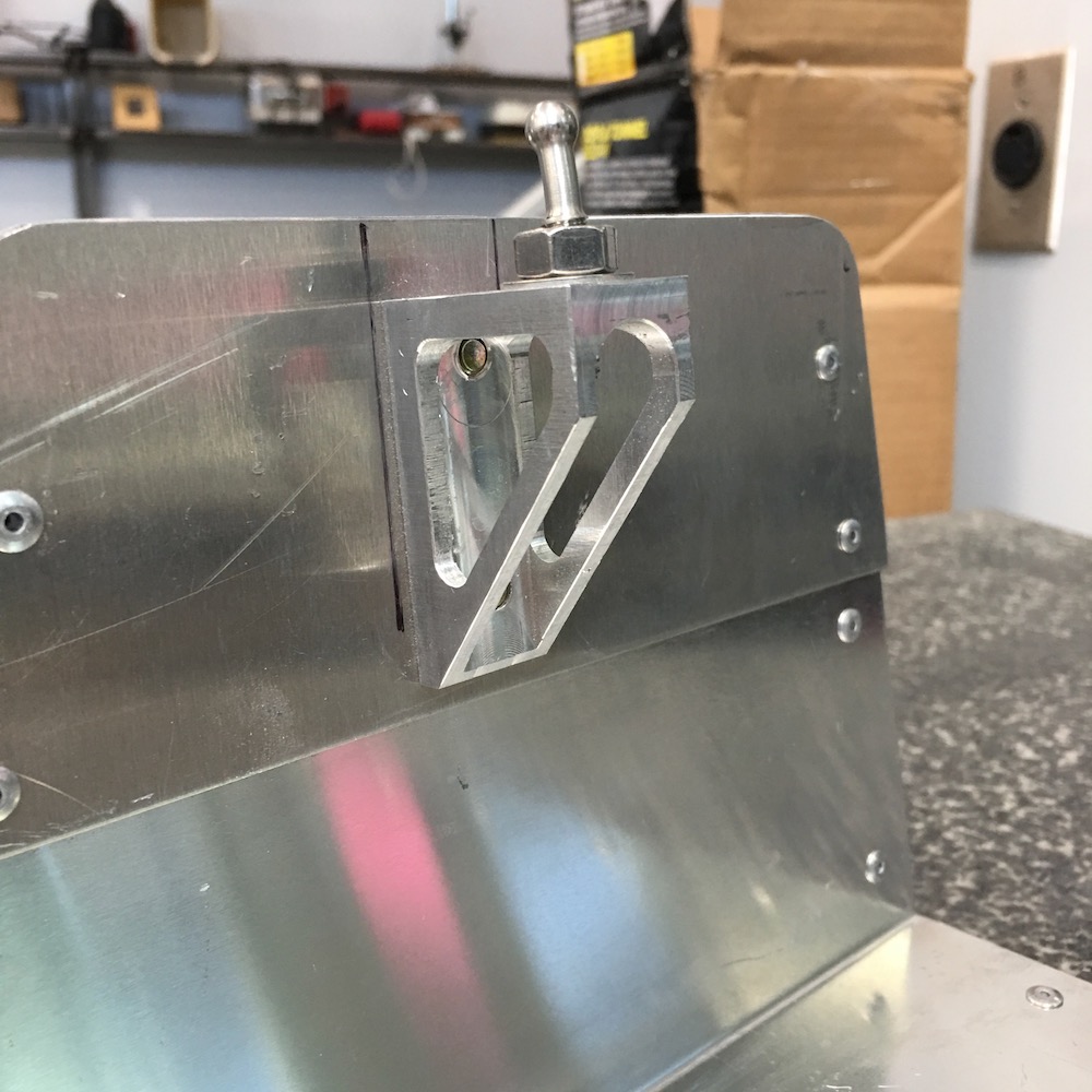
This is the side that will get the Bondo blending.
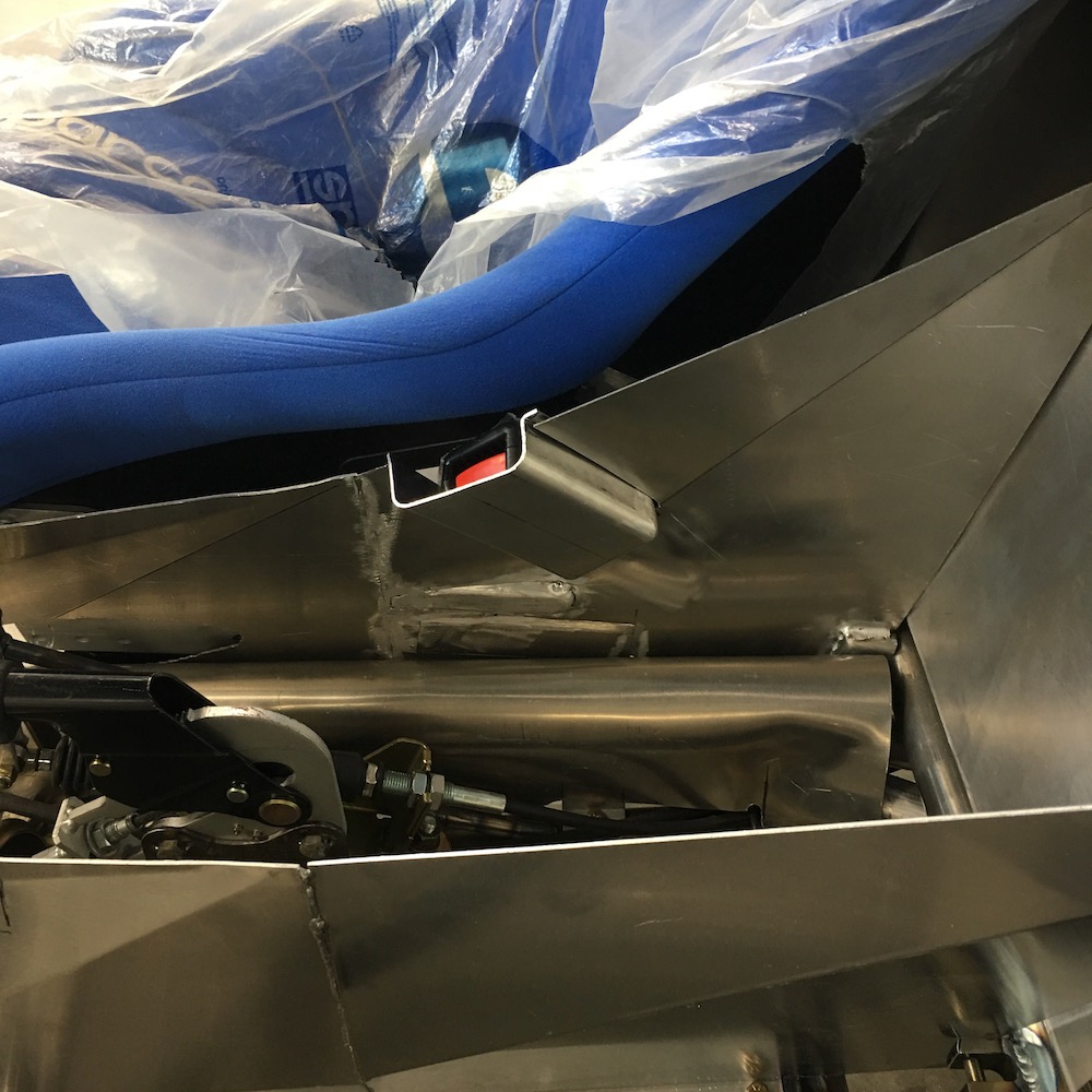
One thing that's proven to be a beast is keeping the panels flat as I manipulate and weld on them. Notice how the edge below the belt latch has a little wave? Yeah, that's gotta go.
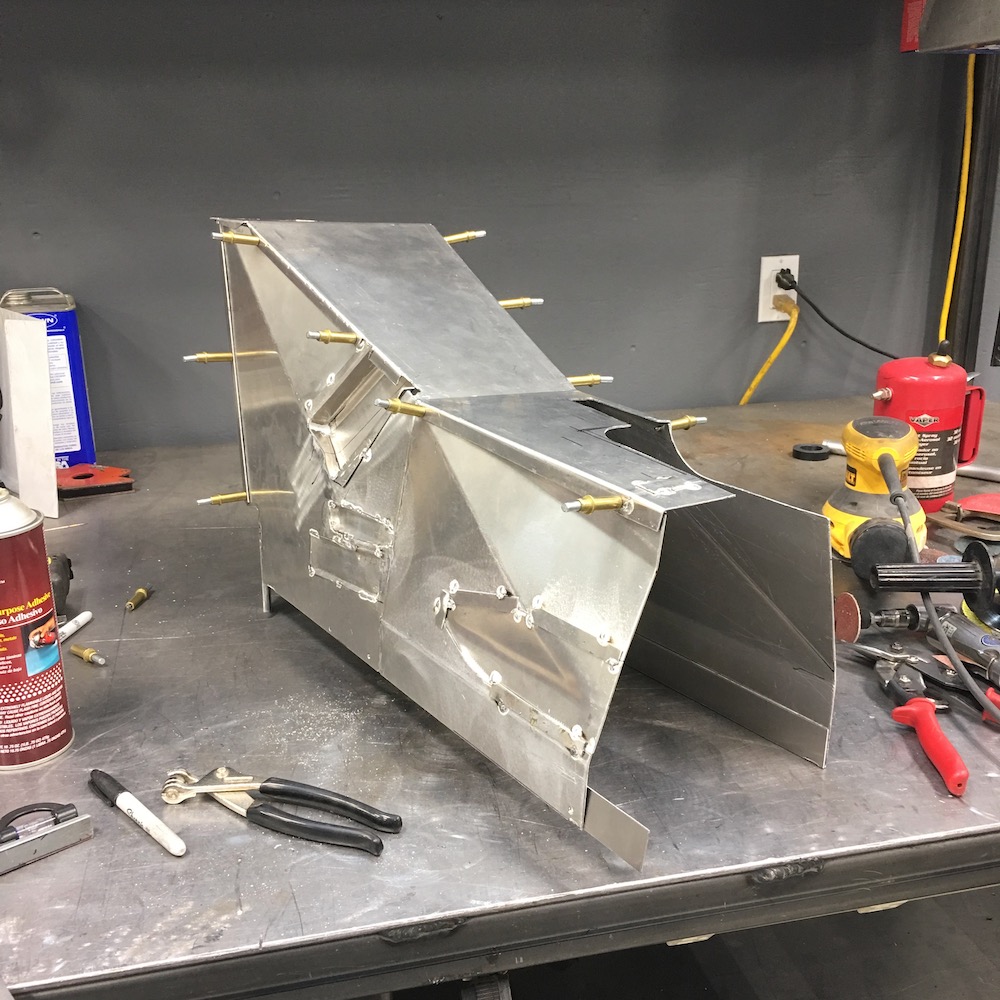
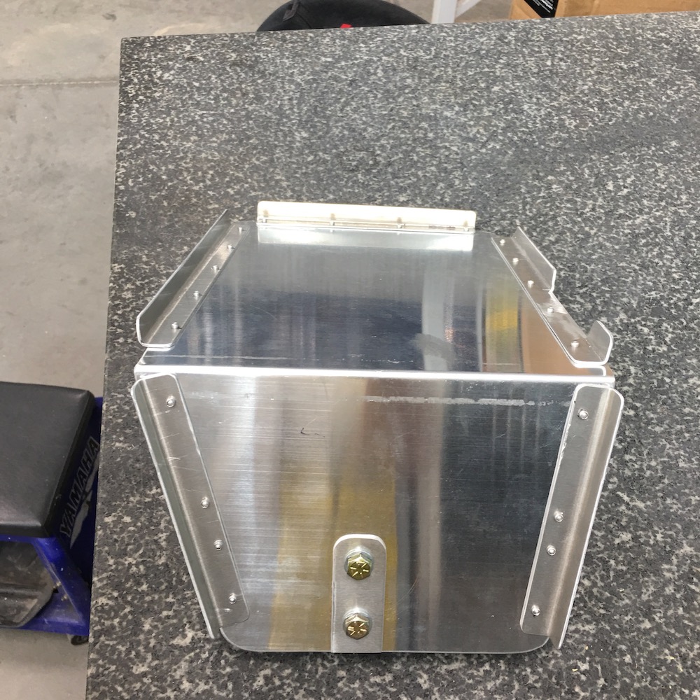
Feb 23, 2020
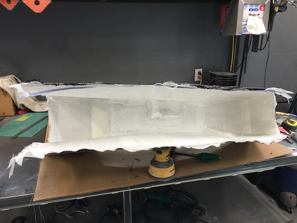
And the back half of the center console mold is finished.
I had to do a little bit of sanding and realized I hate sanding. Looking forward to all the big sanding stuff that's gonna happen here soon.

Mar 23, 2020
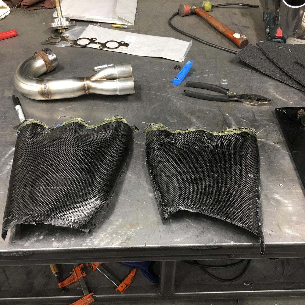
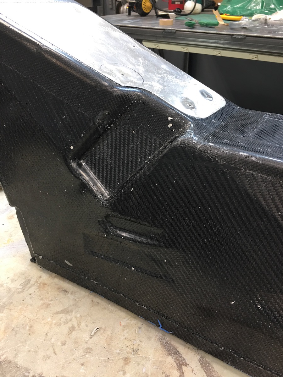
I thought I'd updated this thread a bit better. I've finished a couple carbon items - getting my feet wet playing with the stuff before I tackle the center console, which I'll admit has me nervous.
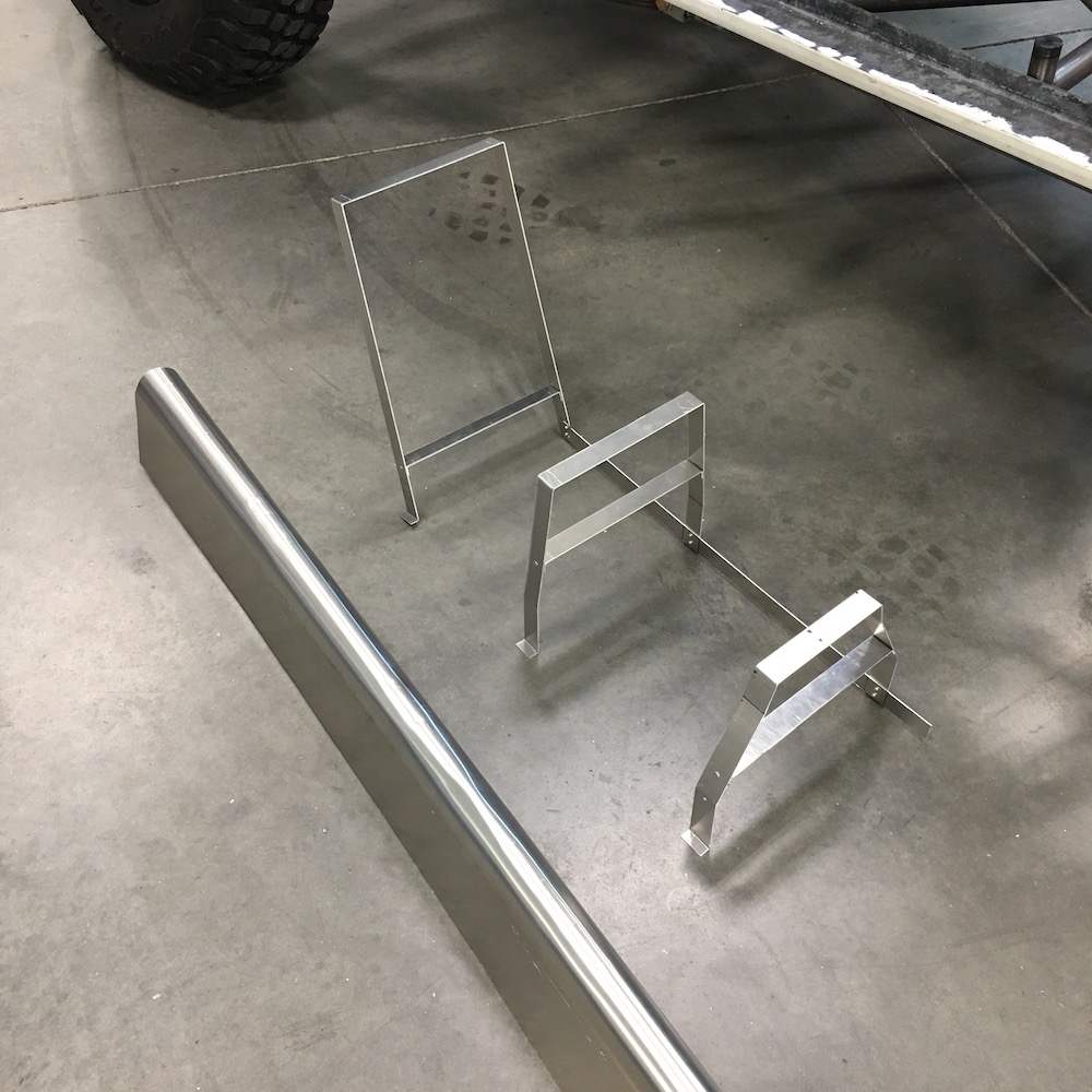
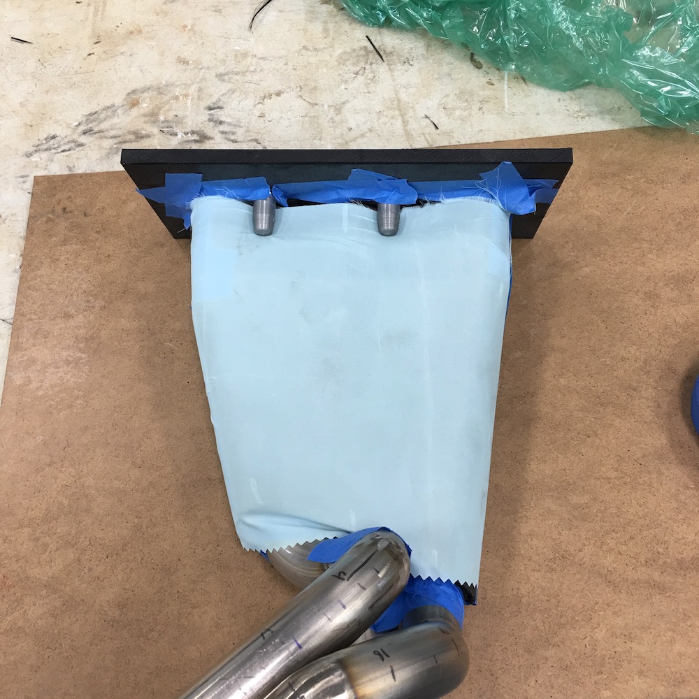
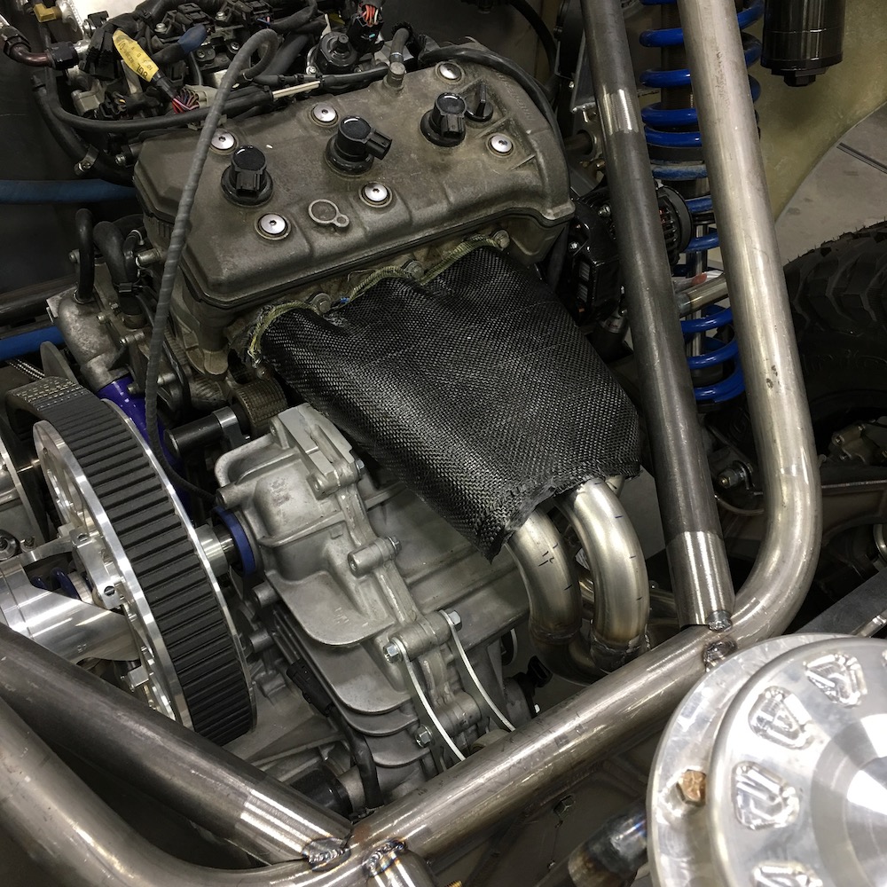
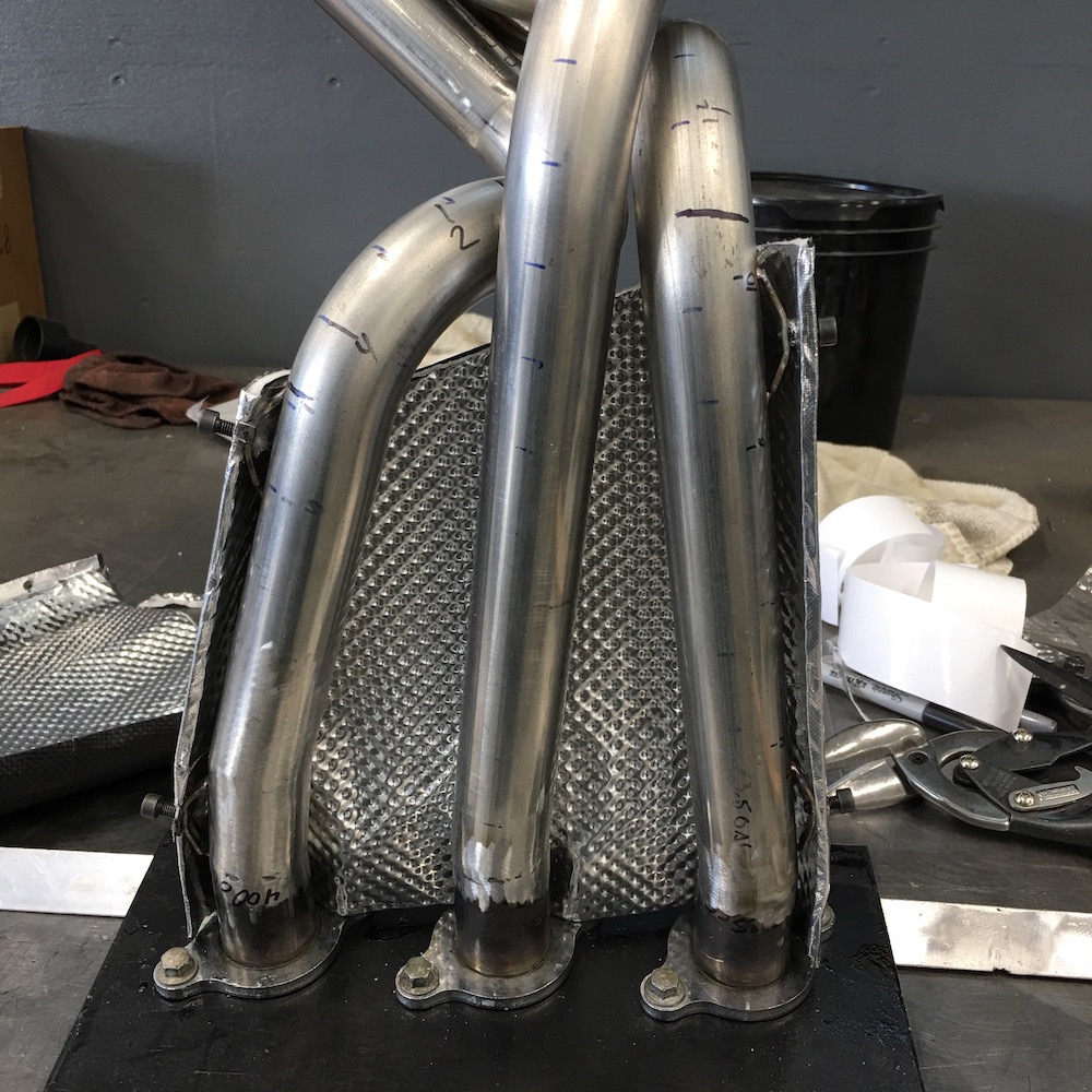
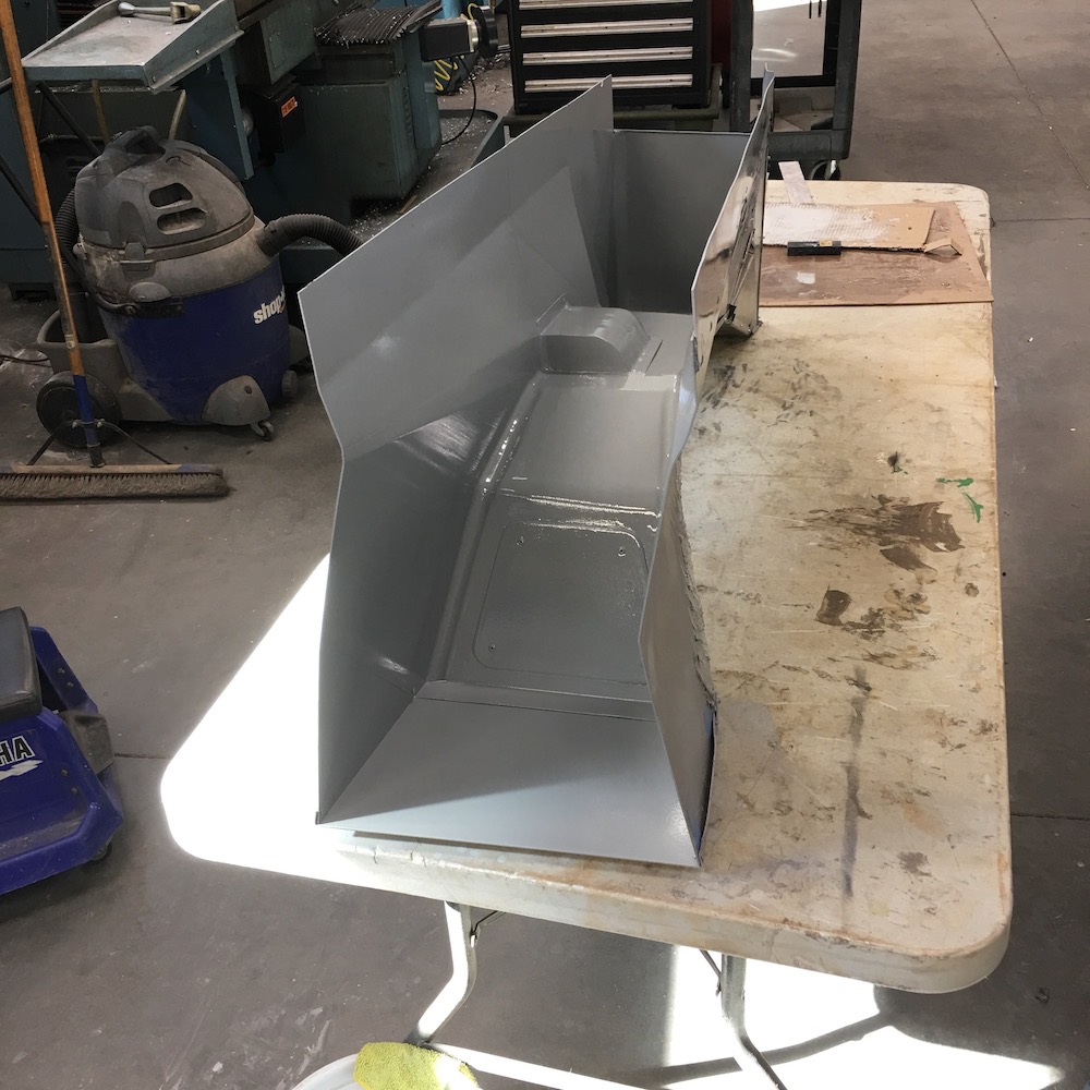
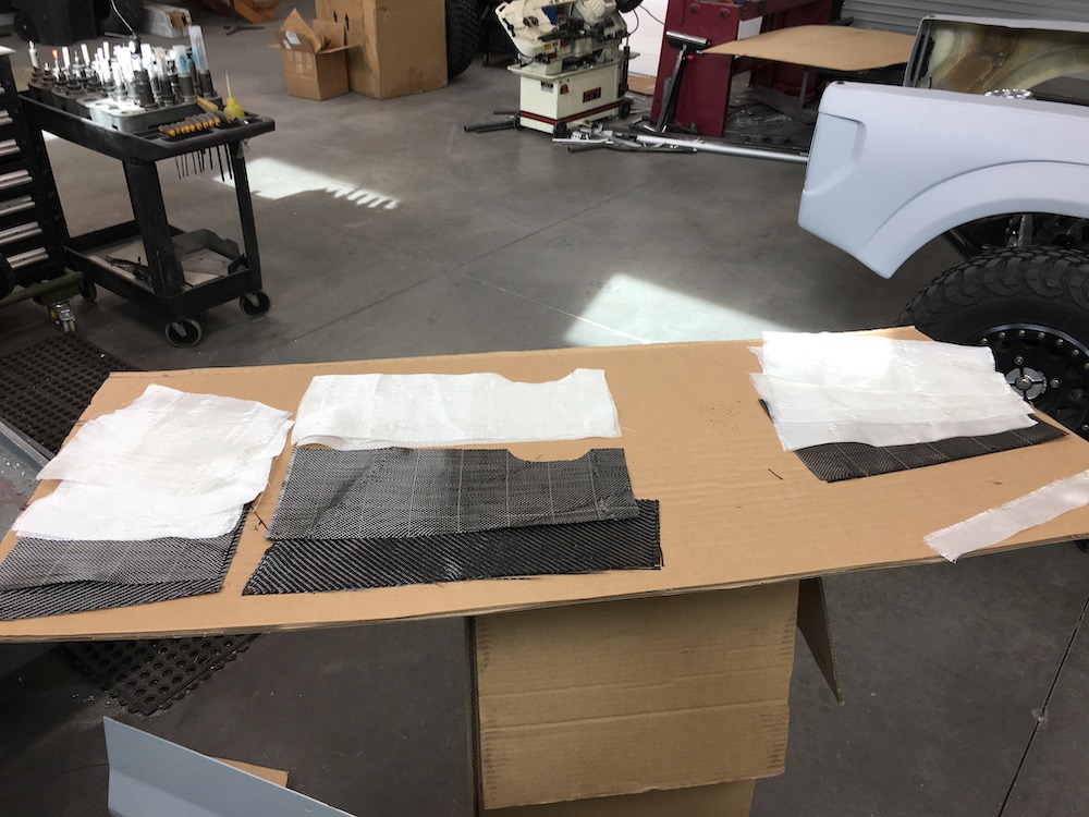
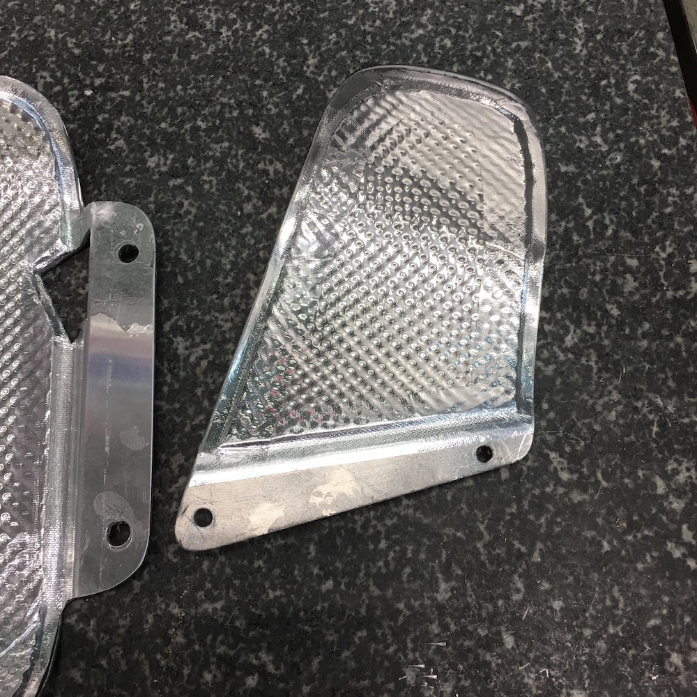
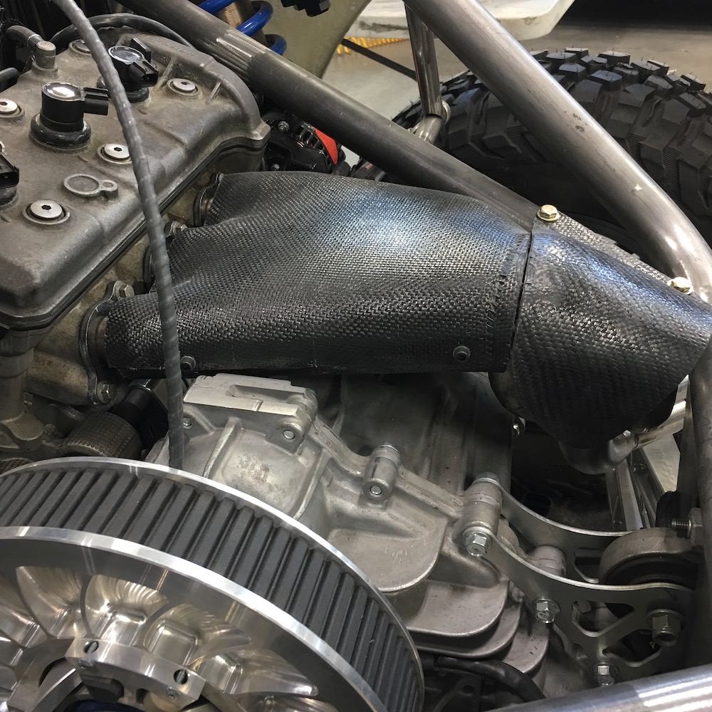
So, first thing was to make a heat shield for the headers. I want to keep as much heat insulated as possible - the more I do, the less I have to worry about chassis invasion from it.
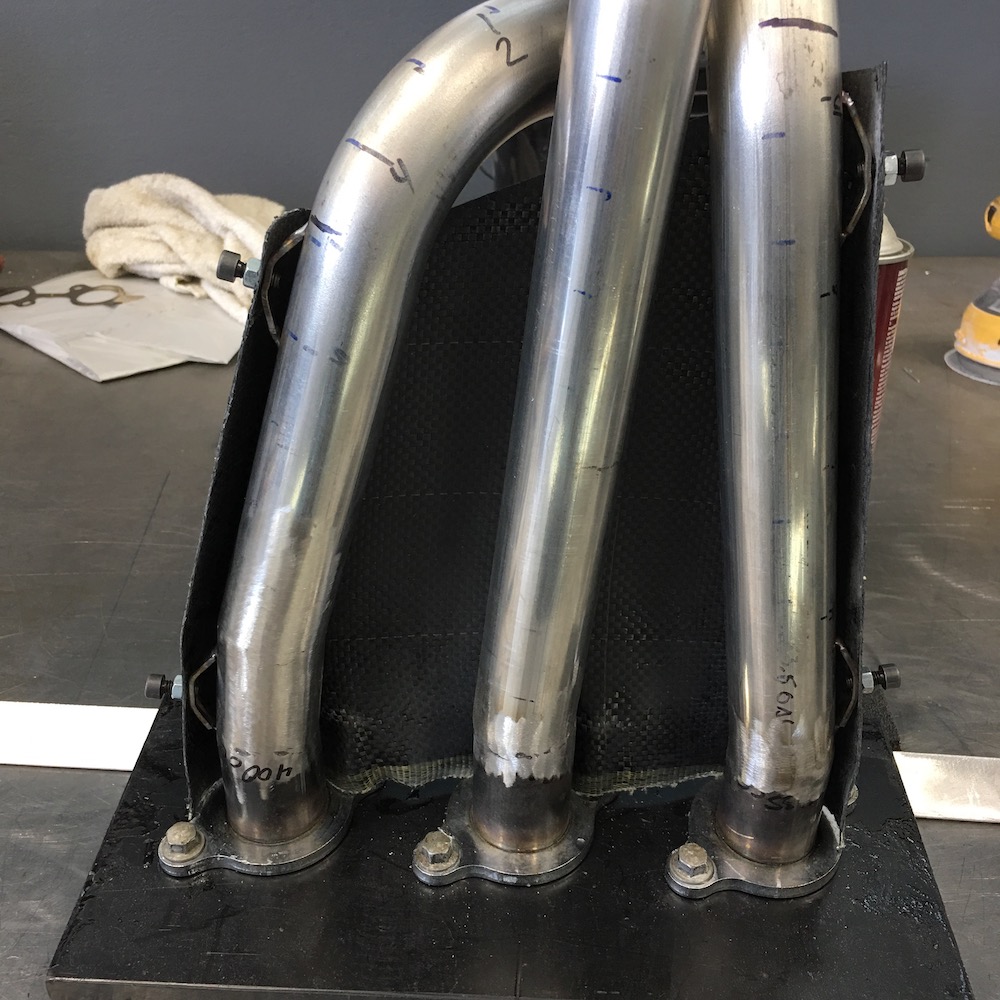
I have some aluminized fiberglass heat shielding that I got from Summit Racing. It's supposed to be good for 1450F and such. Got good ratings. It's 1/4" thick. So I made a jig to hold the header pipes in place and started getting creative. I used 1/8" and 1/4" thick closed cell foam - like they use in automotive upholstery. It's flexible, stretches a tad and makes a nice contour. I used the two sizes so I'd have a 1/8" gap between the header pipes and the aluminum sheeting on the insulation.
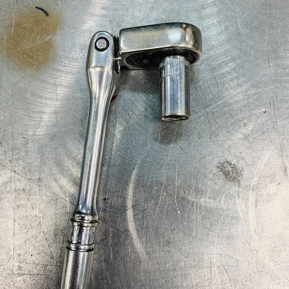
I also got smart (actually had forward thinking...) and made clearance plugs for a 10mm socket - that's what the little cone shaped pieces are.
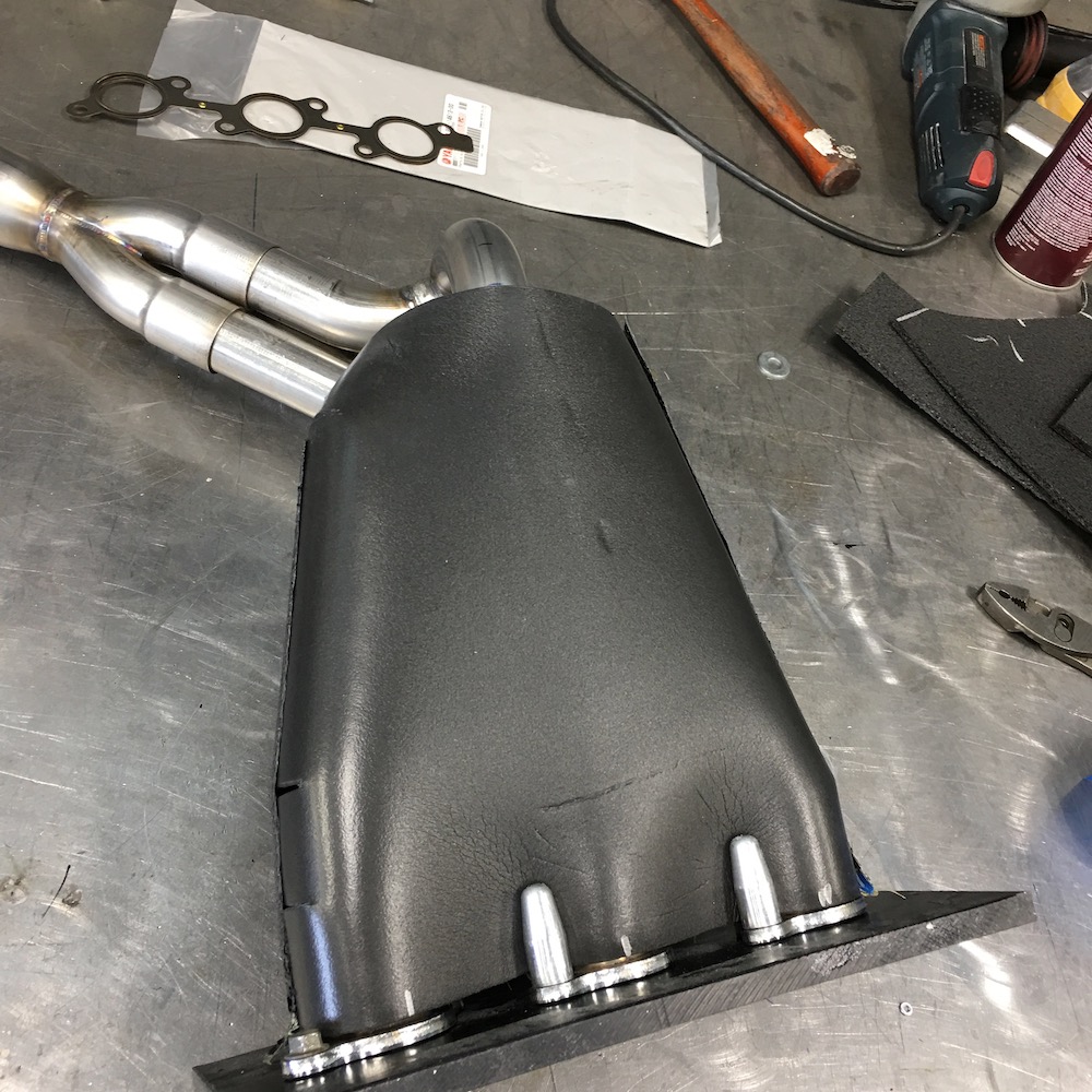
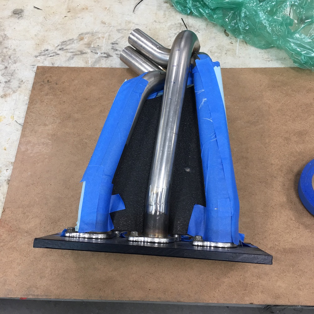
Next I covered the stuff in wetted out carbon fiber and peel ply so the carbon doesn't stick to the foam shape.
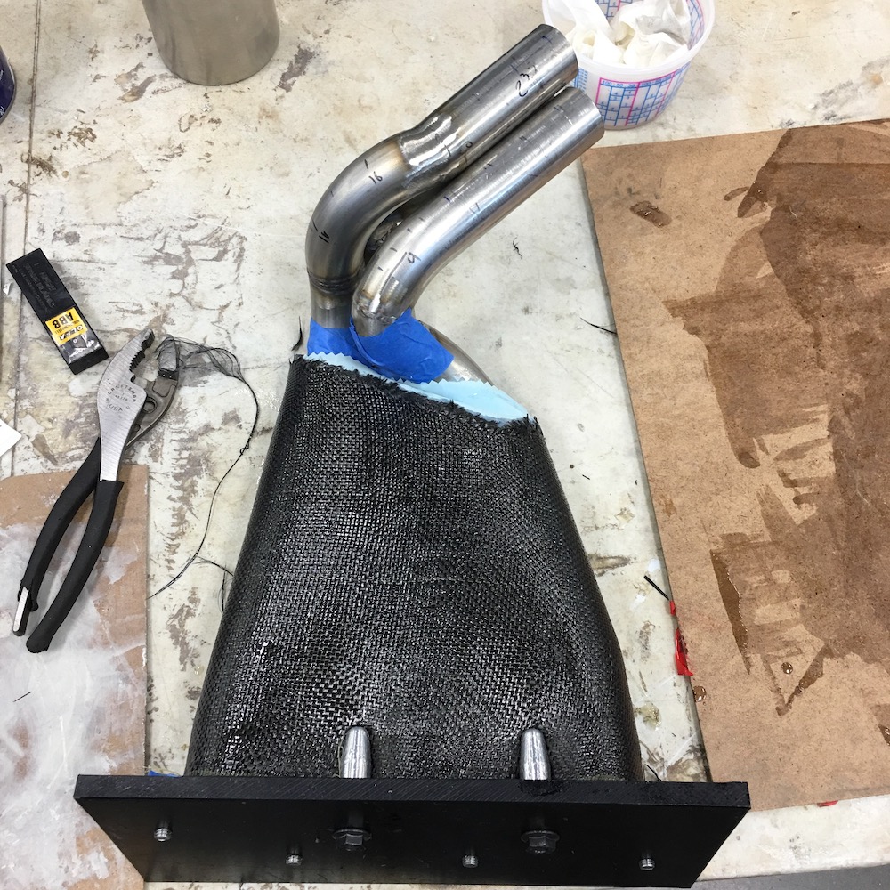
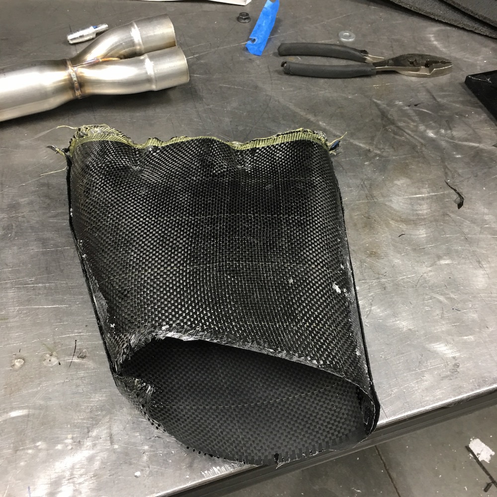
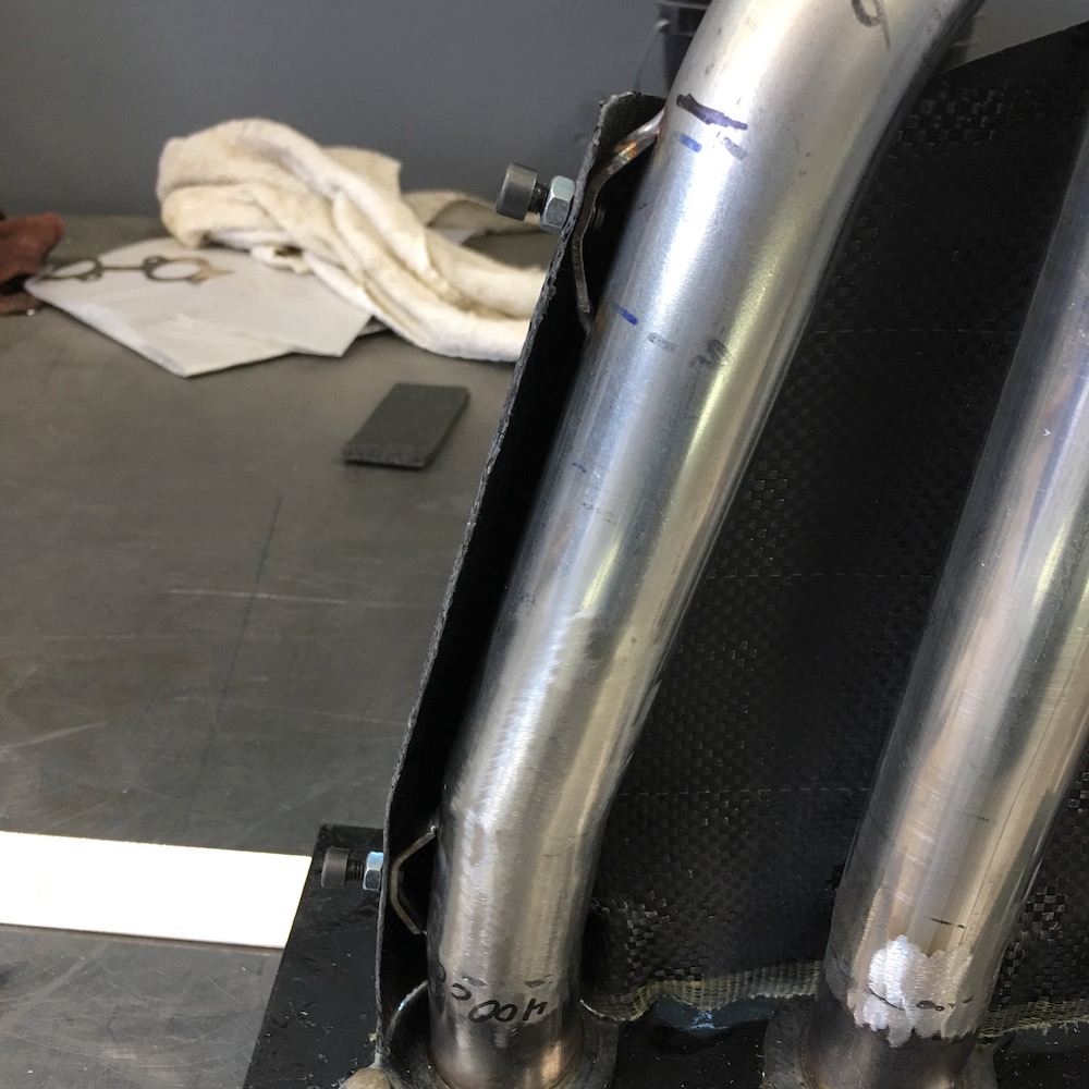
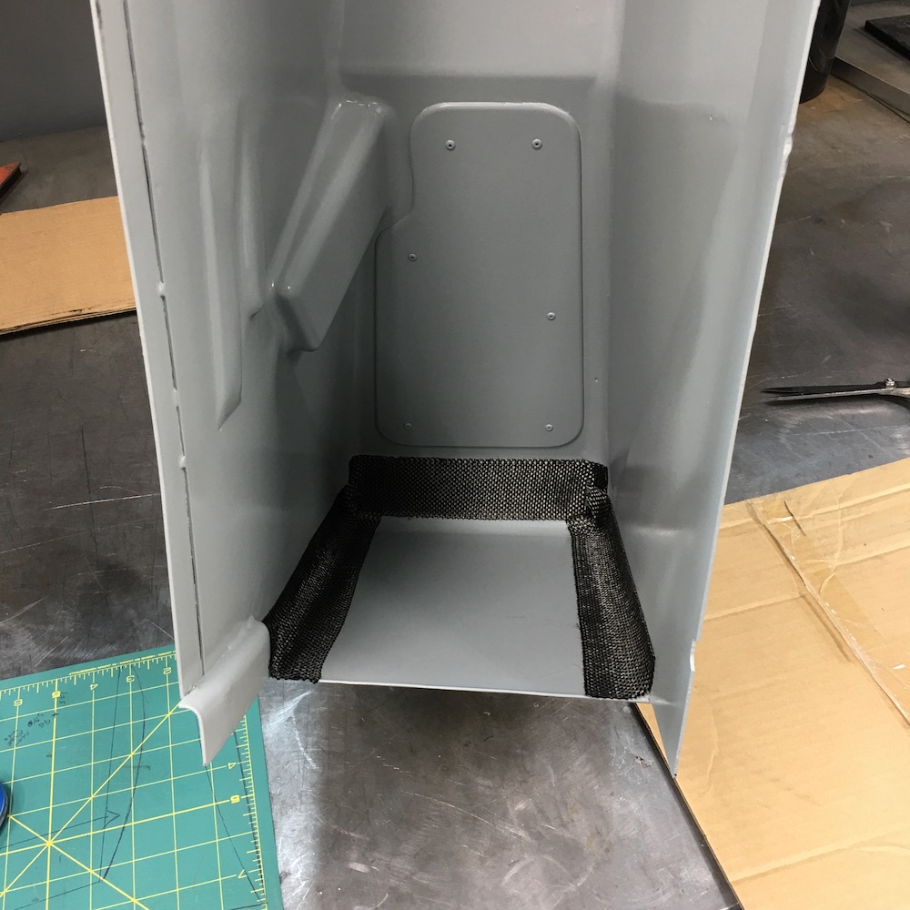
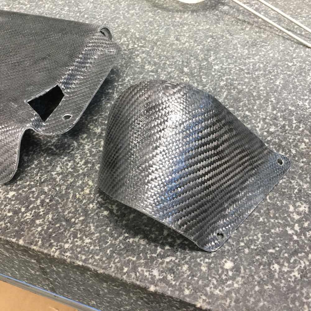
Clearance seems to have worked out with the bottom half:
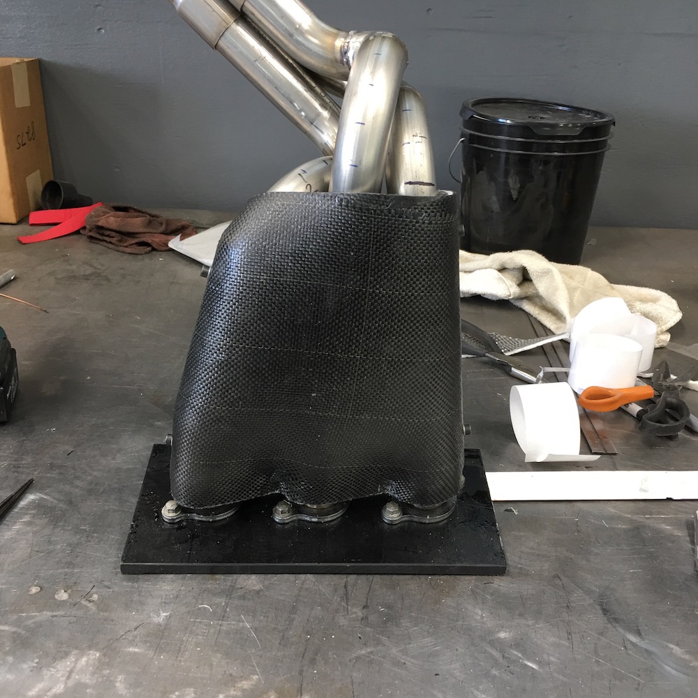
I wrapped the upper half of the headers with the two layers of foam and the fit of the bottom piece was perfect - clips in place:
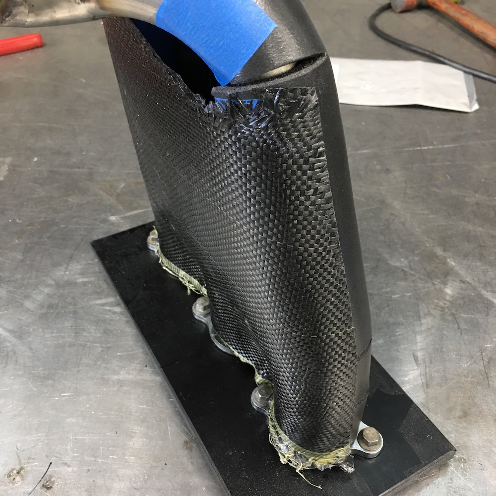
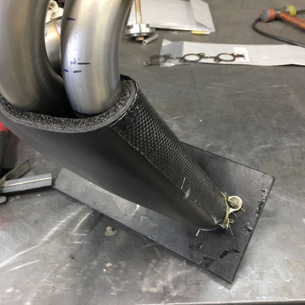
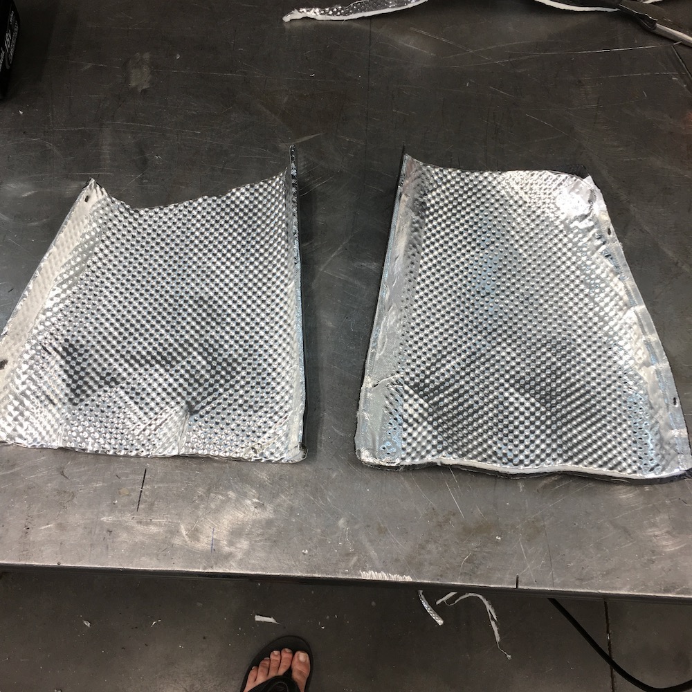
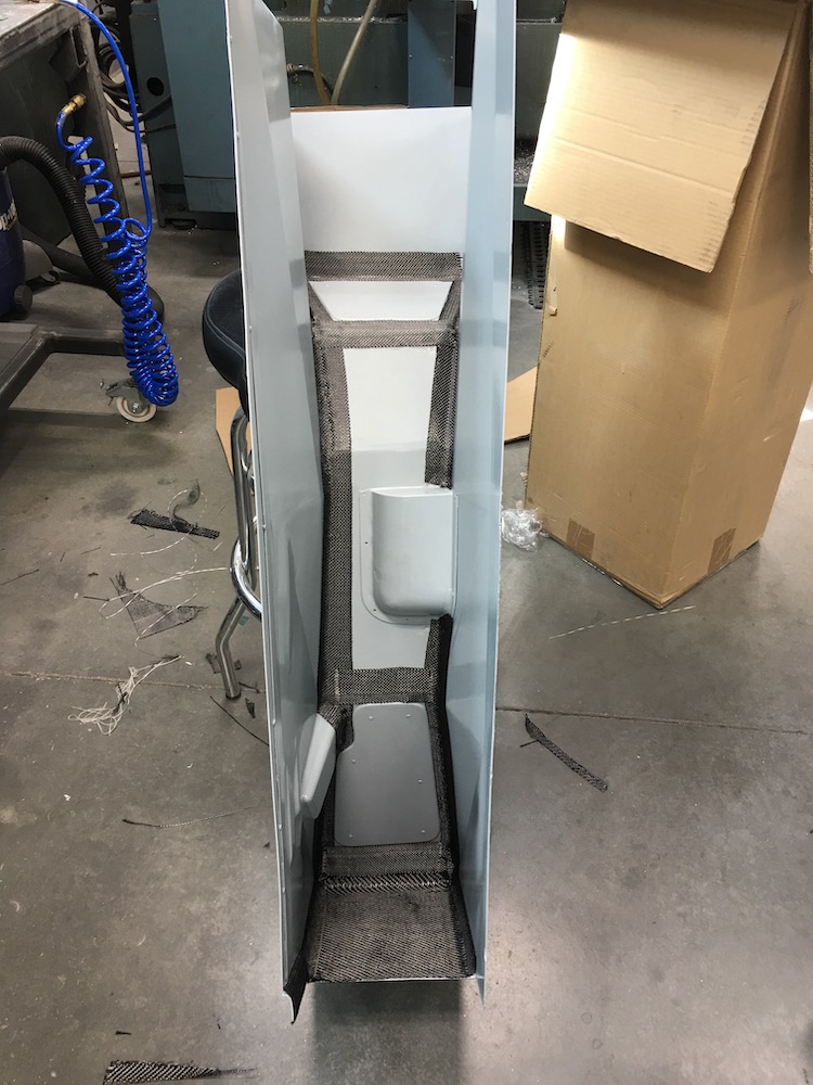
Two more layers of carbon and I have a top cap:
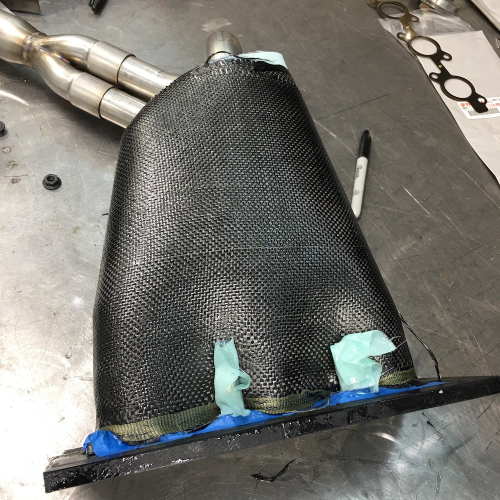
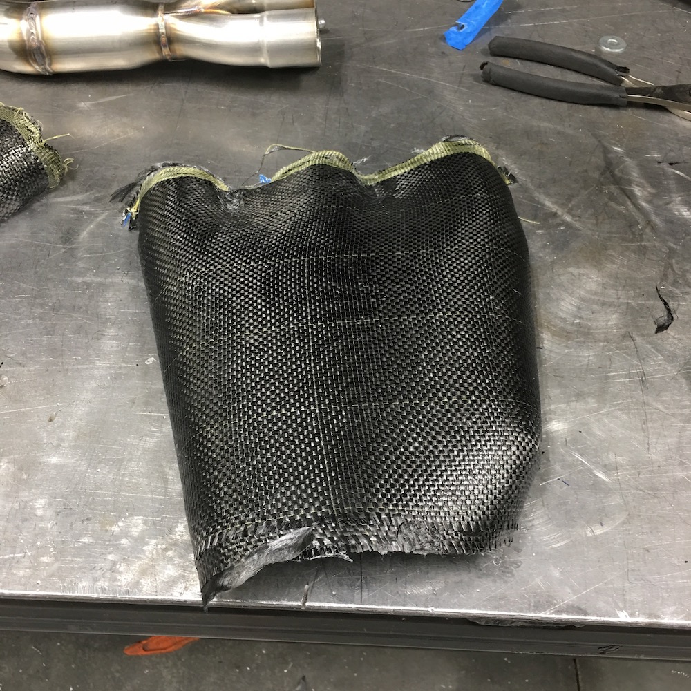
Both halves:
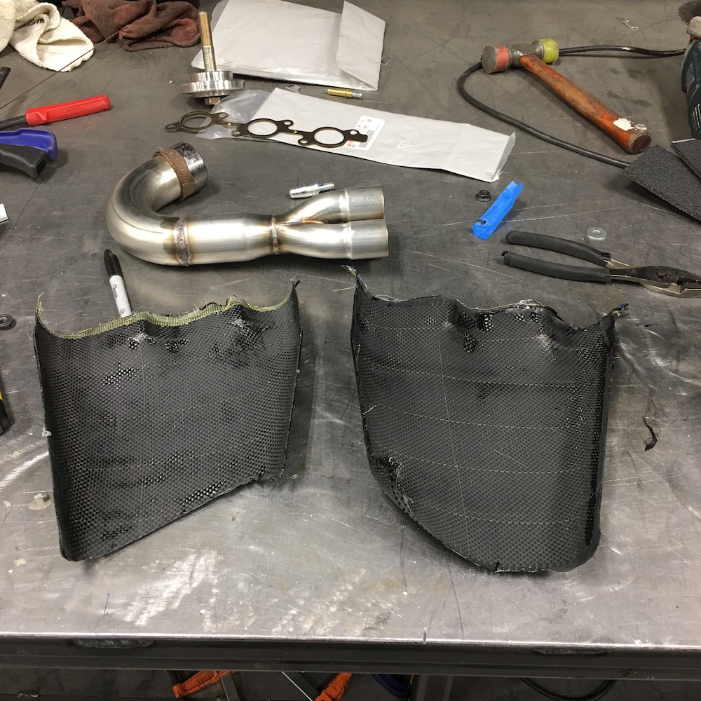
They almost snap together:
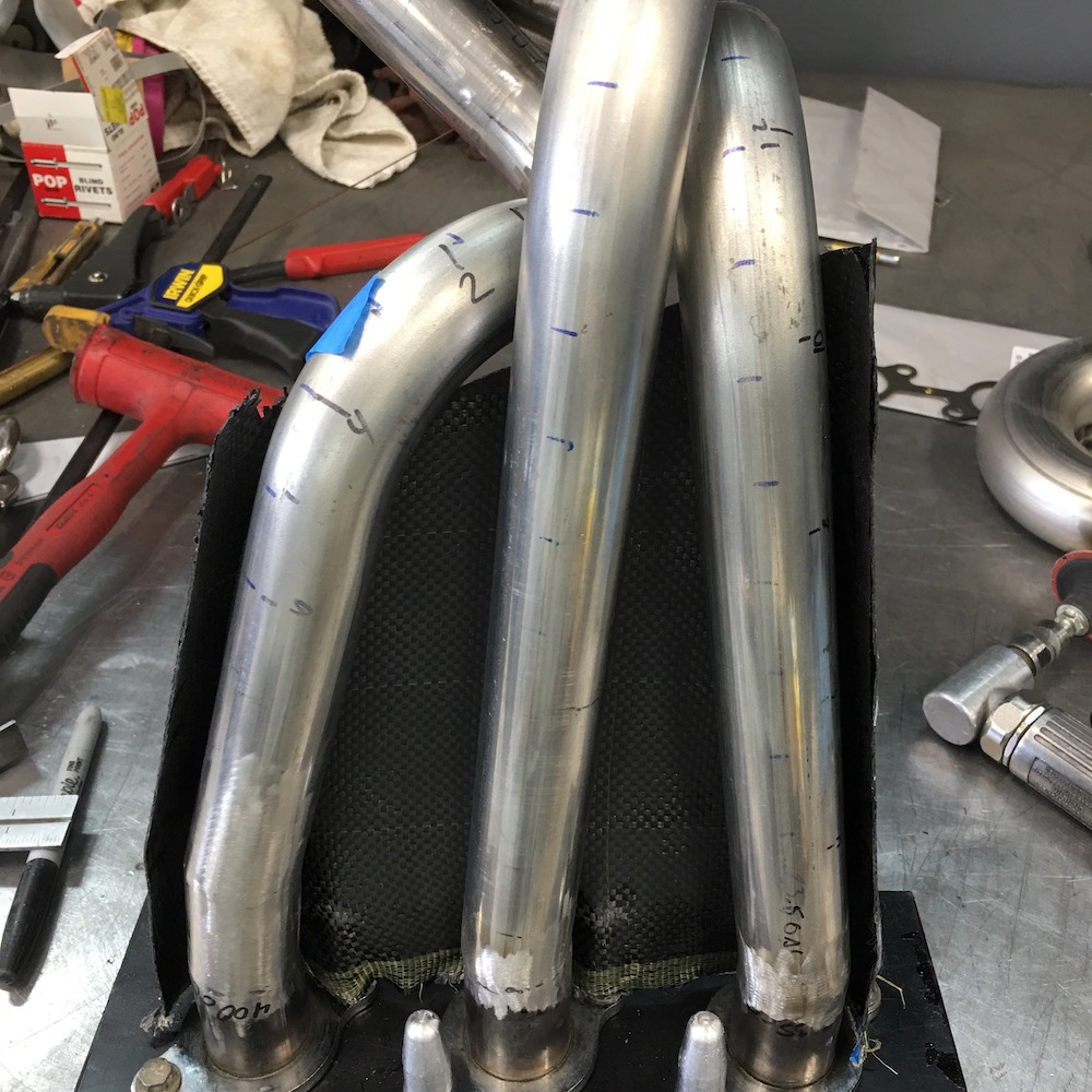
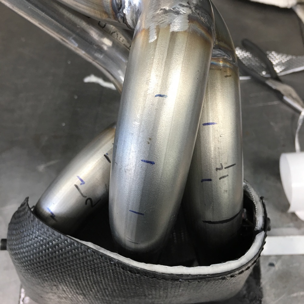
Bottom one may have some clearance issues - I'll tend to them later if I do. I can't put it in with the header in place but I have a plan. The middle header pipe isn't attached to anything. Being that the two outer pipes are located by the shield I should be able to just bolt the system in now and all the bolts are reachable. There may be one spot on the top of the trans that hits the shield and if it does I'll just cut a window into it or if it's a minor issue, grind the offending fin down.
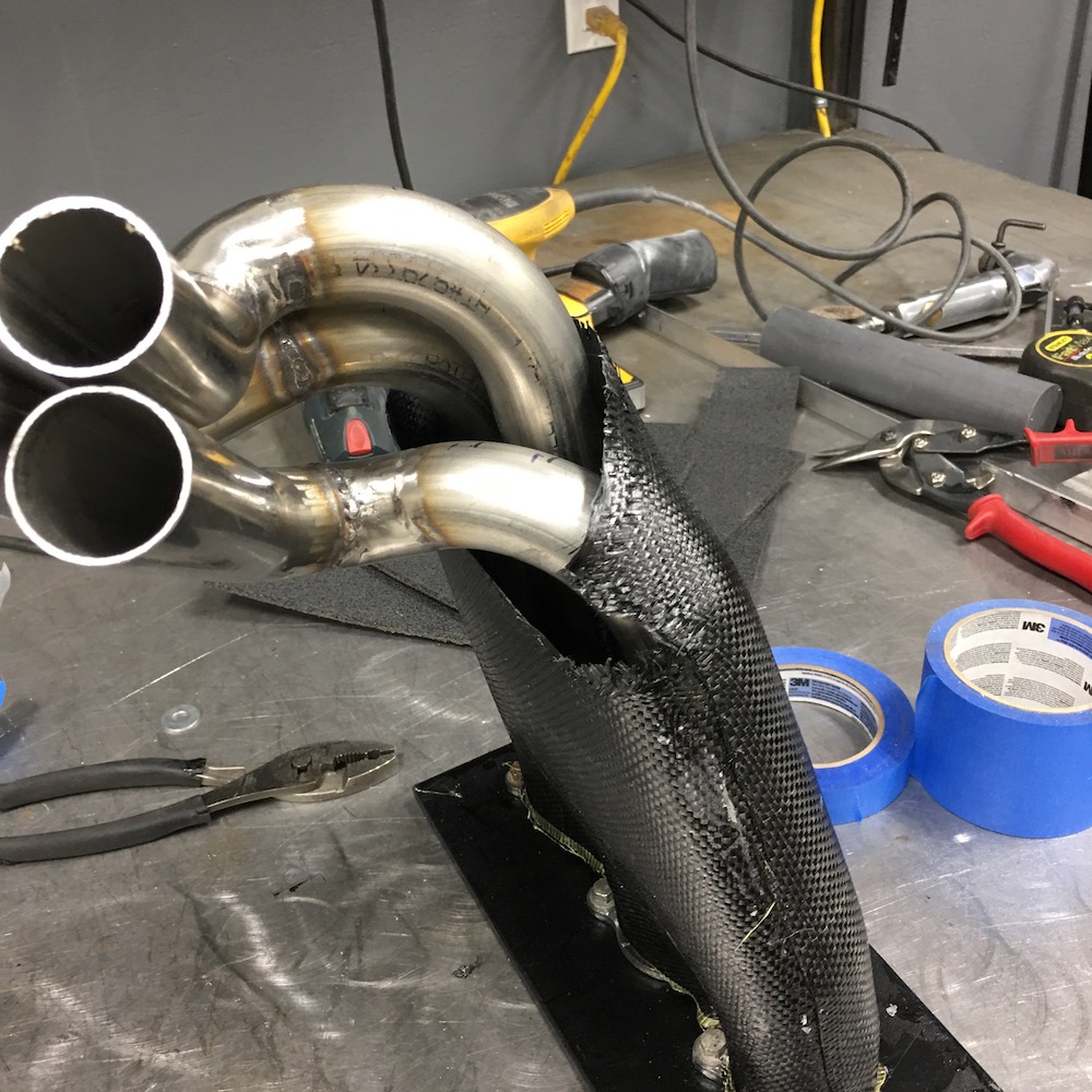
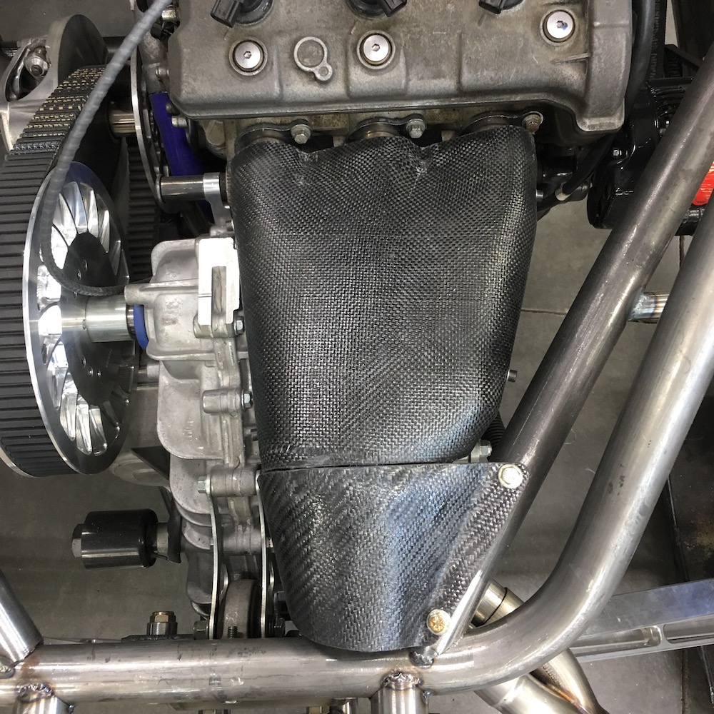
Standoffs - tried to make them a bit longer than just a nut - not sure how much heat they'll insulate from but it's worth a shot.
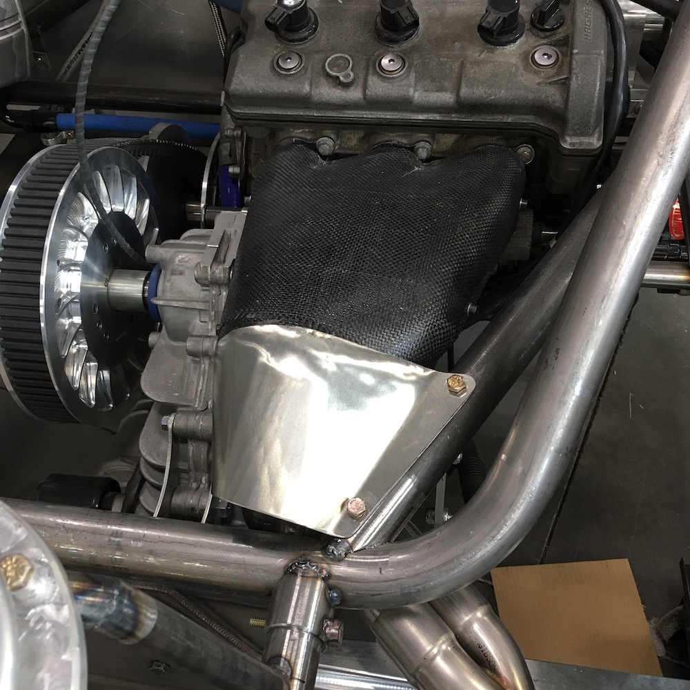
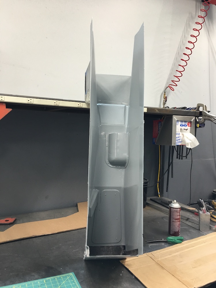
Heat shielding in place:
Good clearance between the shield and the headers:
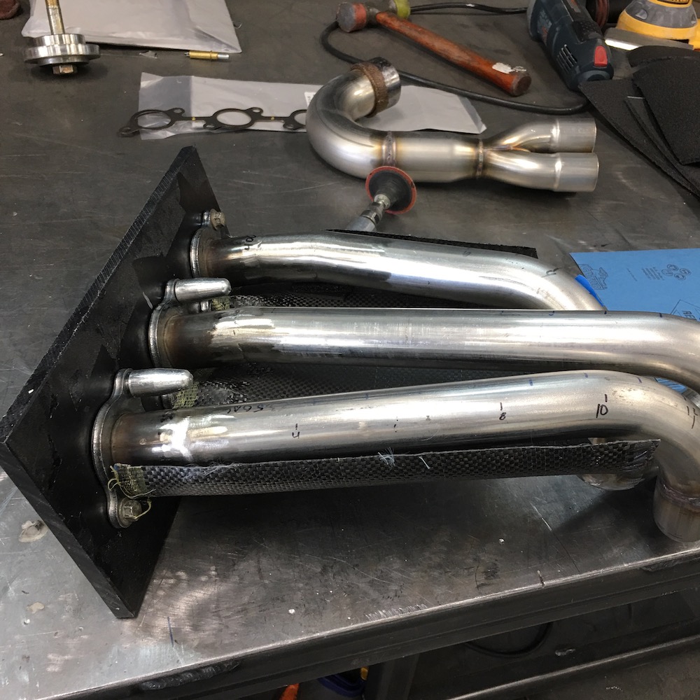
Top shield in place:
Looks like quite a bit of room at this end:
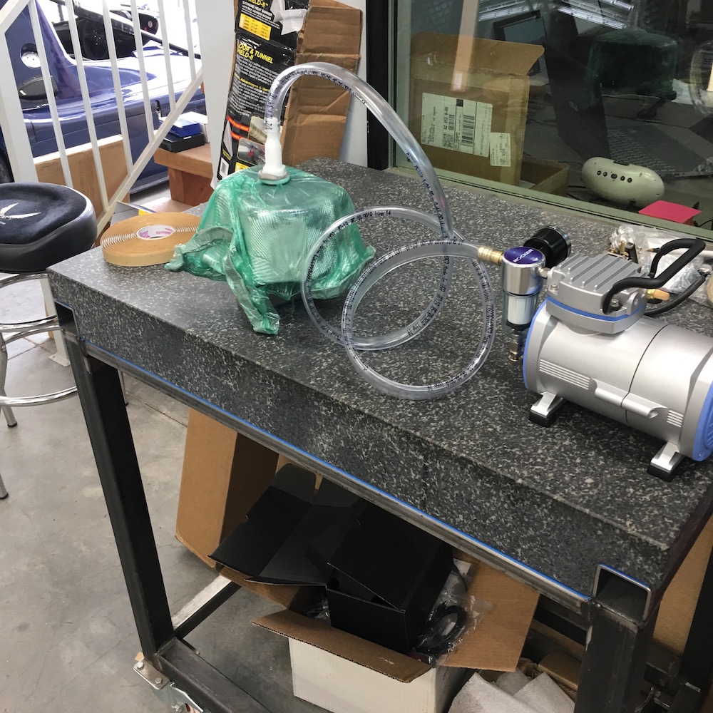
I also started messing with a vacuum bagging piece - the steering column bezel/cover/what ever you wanna call it.
Started out with two pieces of styrofoam Super77'd to the base of the steering and started forming. Throw down a layer of Bondo, sand, Bondo, sand, repeat three times.
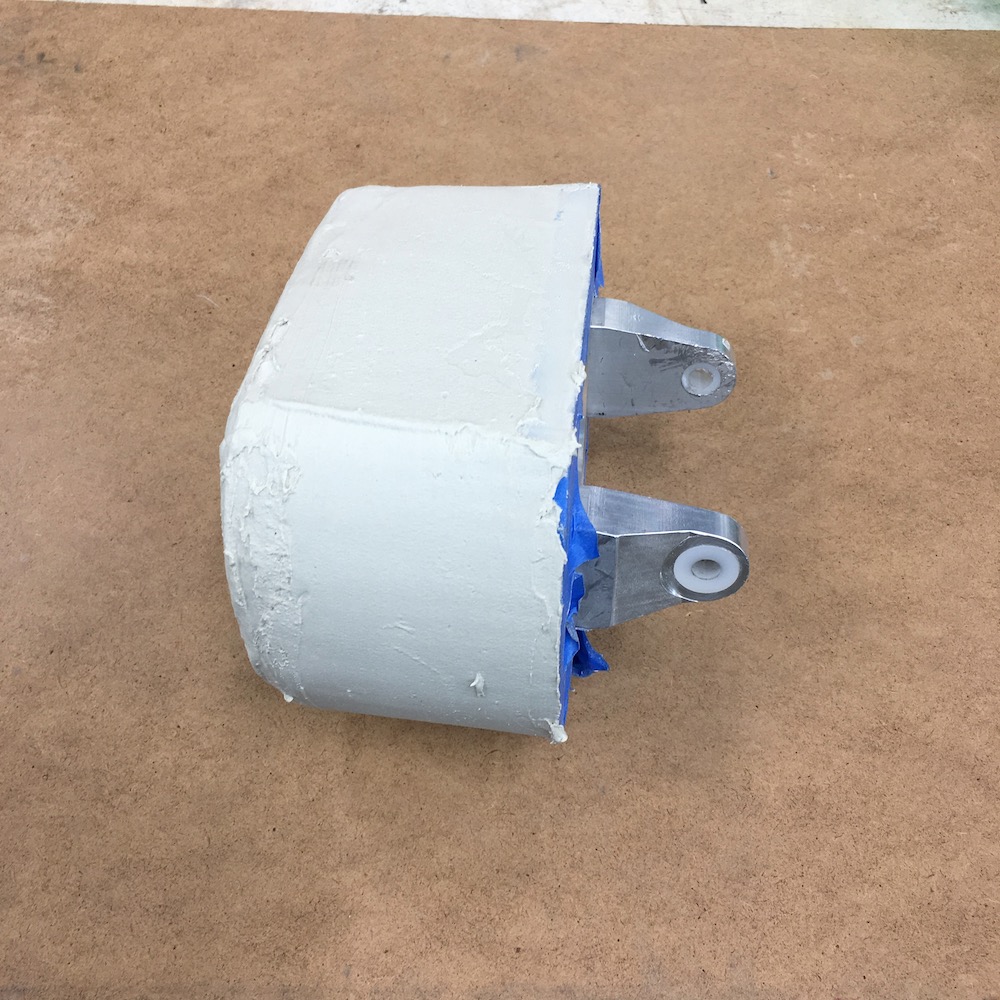
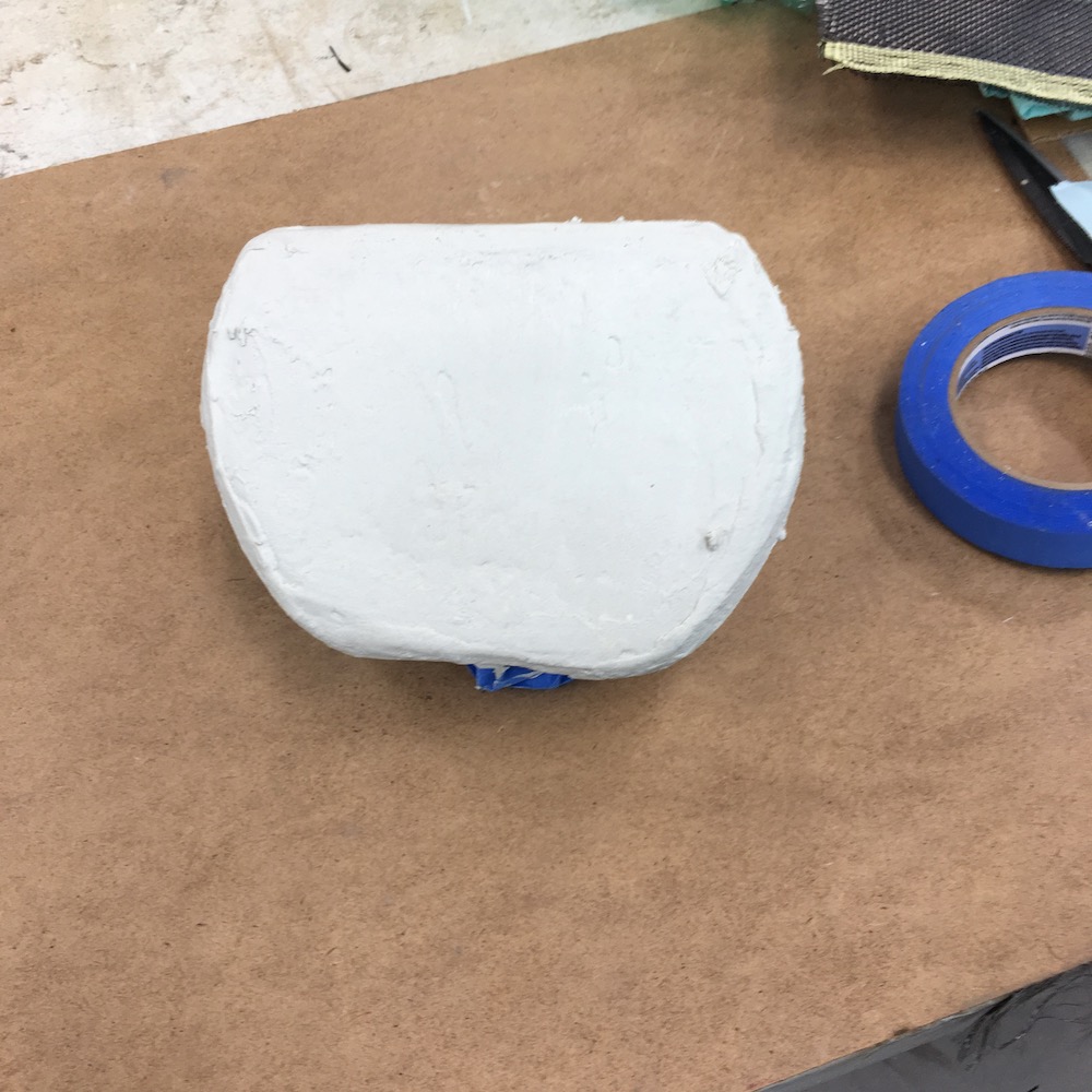
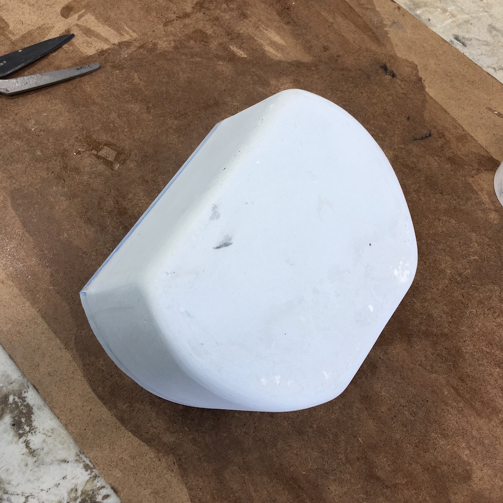
Then take two strips and two caps and Super77 them into place. I did a wrap around the body and then a top cap. Repeated for a second layer. The Super77 sticks stuff down nicely (got really good edge lines) and doesn't interfere with the epoxy when I wet the fabric out. It's not a structural piece so I'm not worried about strength. Heck, it's only two layers thick which works out to about .024".
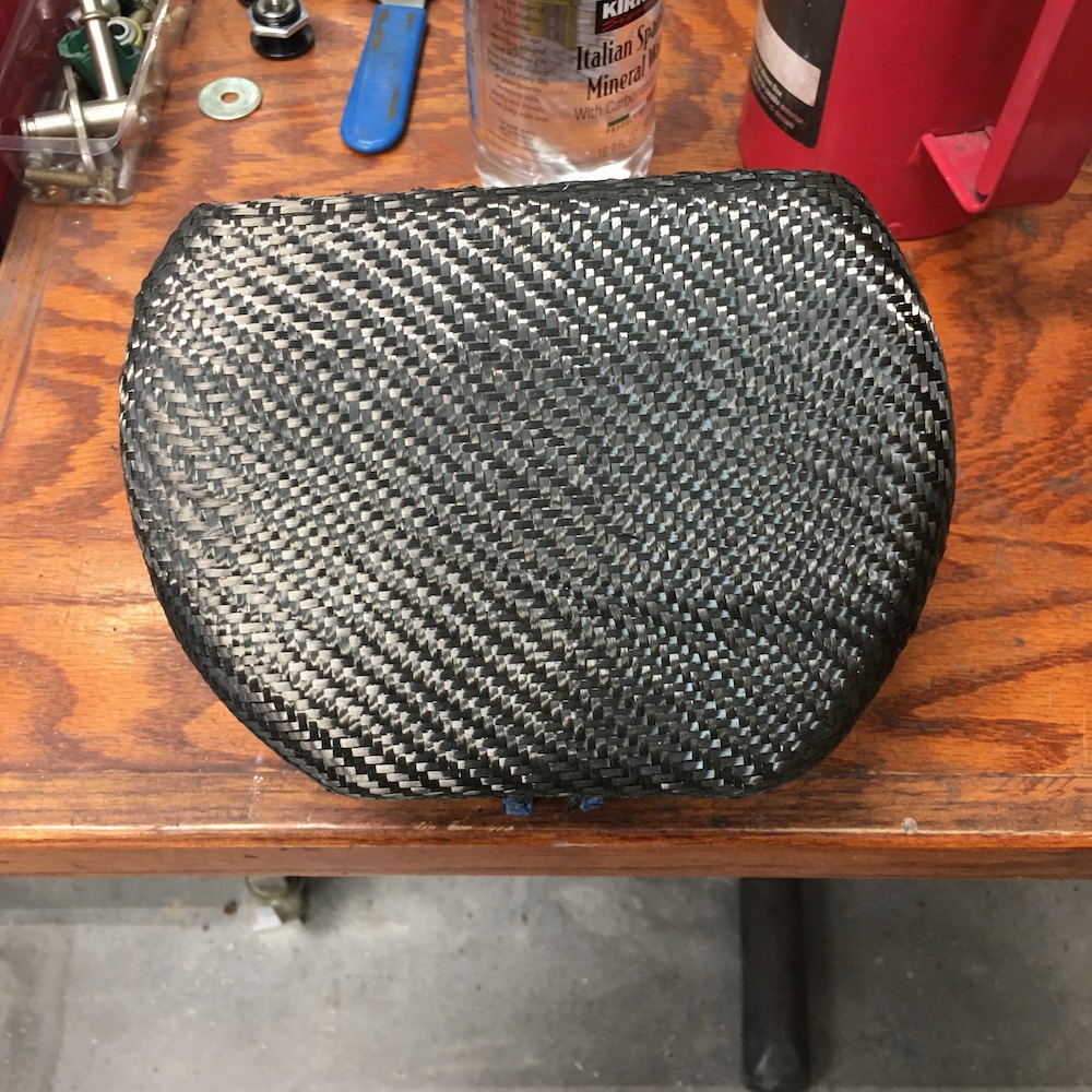
Vacuum bag time:
Overall I'm pretty pleased with the way it turned out. I got some funky lines and a bit of porosity but it's nothing a good coat of polyurethane won't cover up.
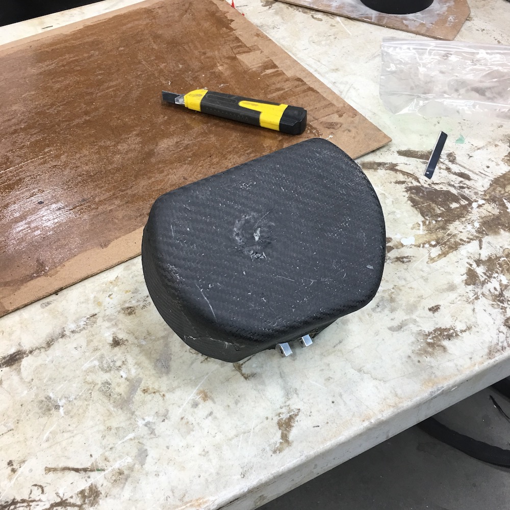
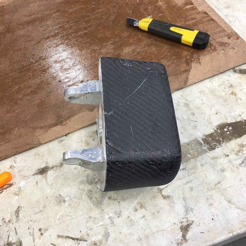
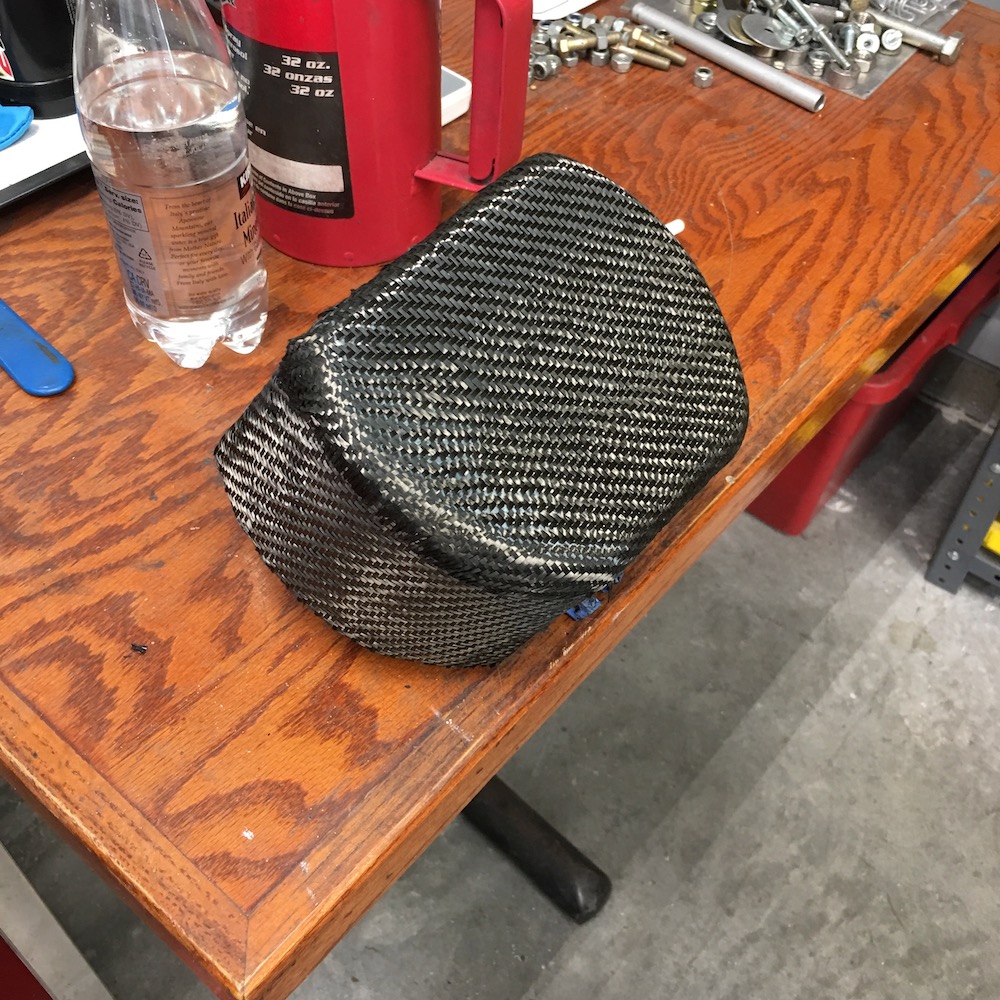
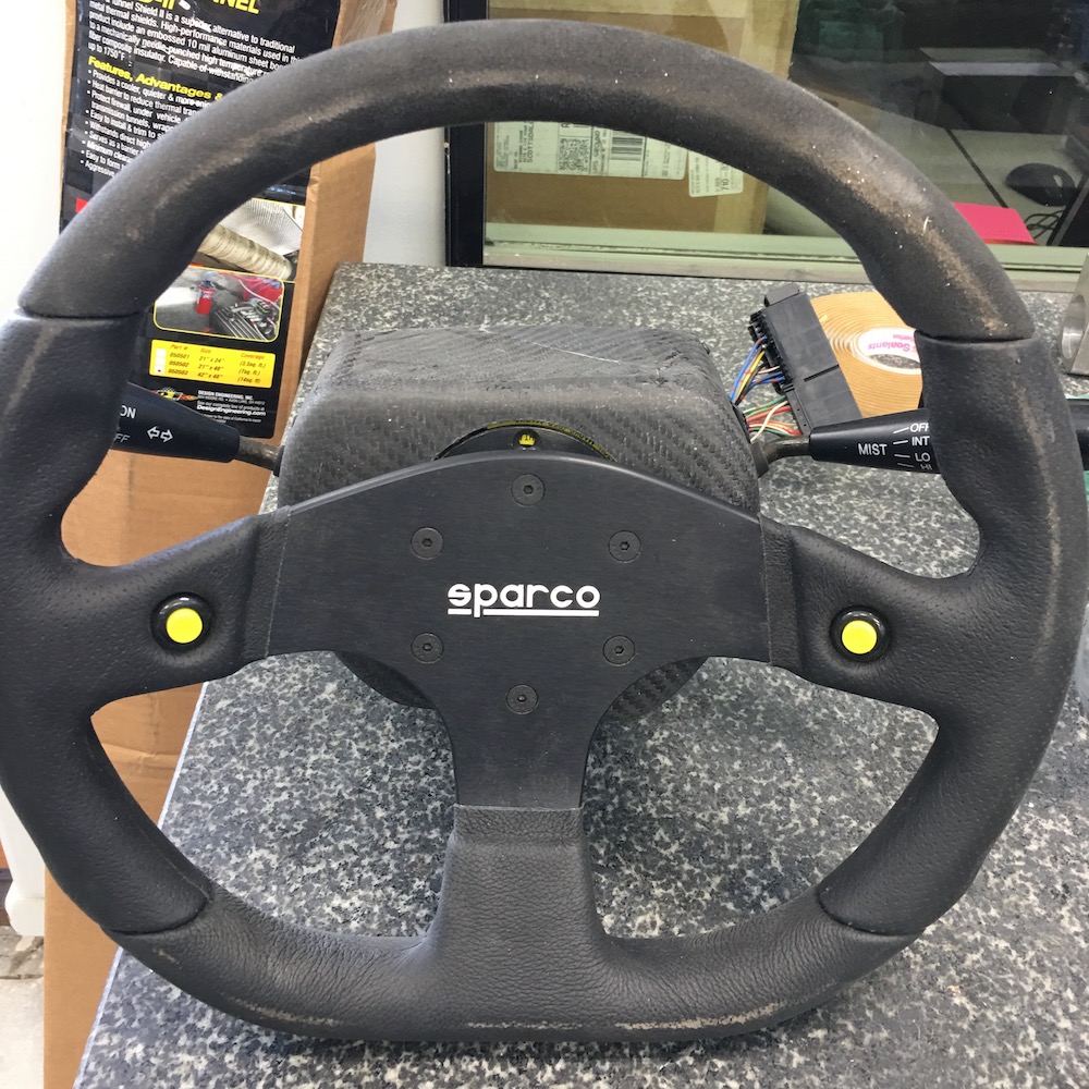
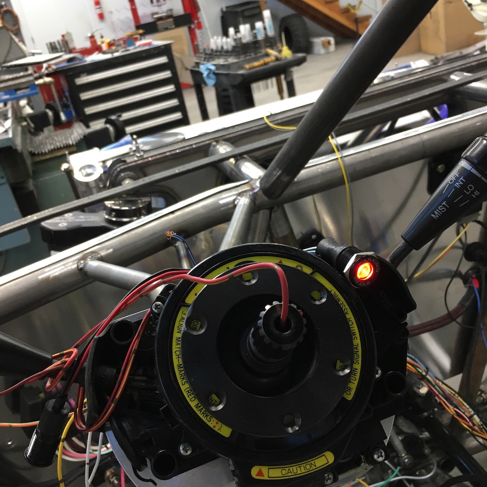
Cut the windows for the turn signal and wiper control stalks and the hole for the quick release. Really liking the way it came out too.


Next I'll go stare at the center console and figure out my attack plan. We have guests the next few days so it's gonna be at least two weeks before I get my hands sticky.
Apr 4, 2020
Header cover turned out to fit nicely. Had to grind a little bit of clearance on a trans case fin but other than that it was bolt in. WHEW!!!
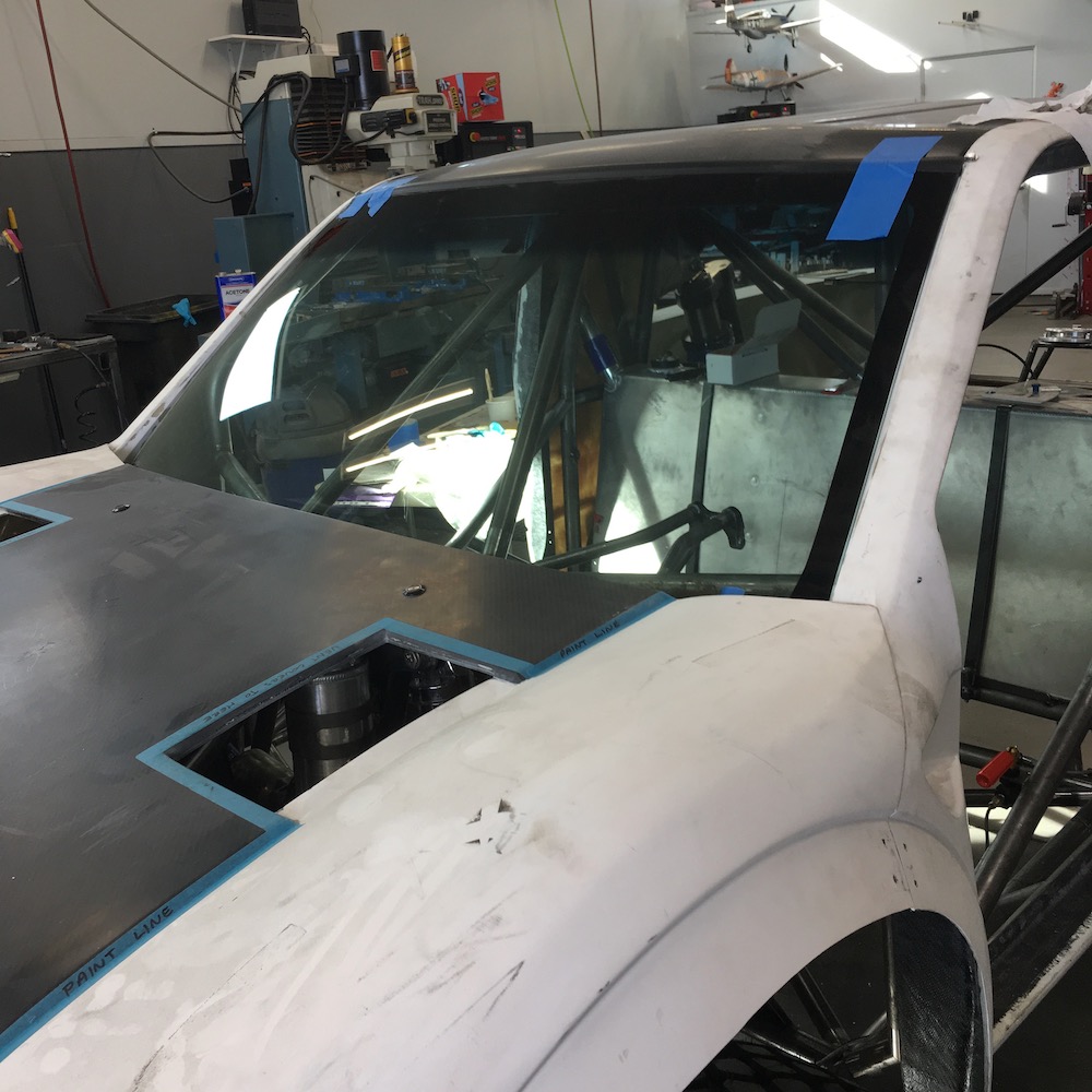
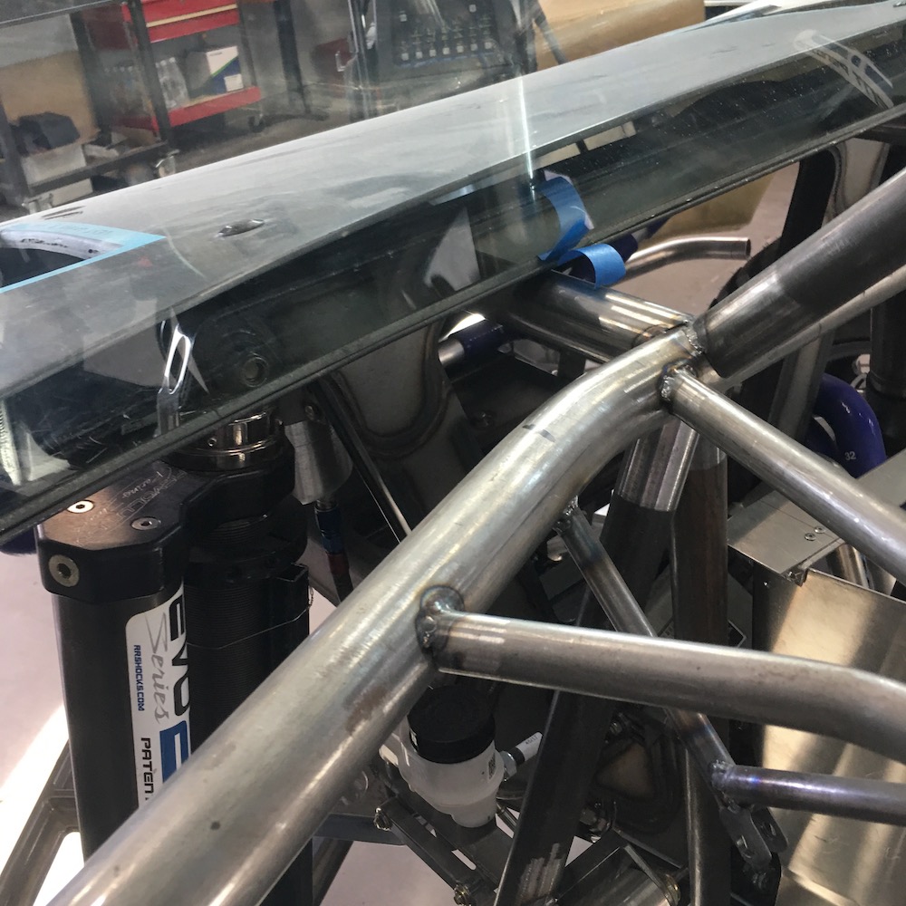
Got the windshield fitted and the lower frame rail formed. Still have to weld the rail in and brace the ends:
Since I'm getting ready to learn vacuum infusion I may as well test it on some smaller parts.
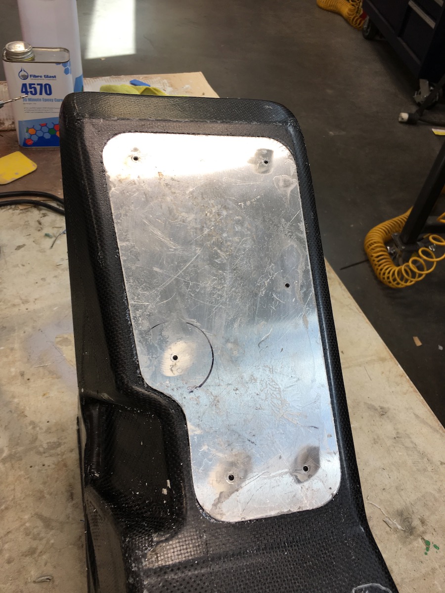
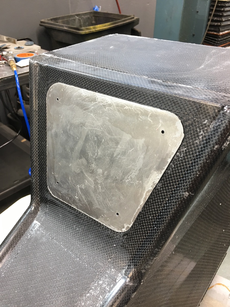
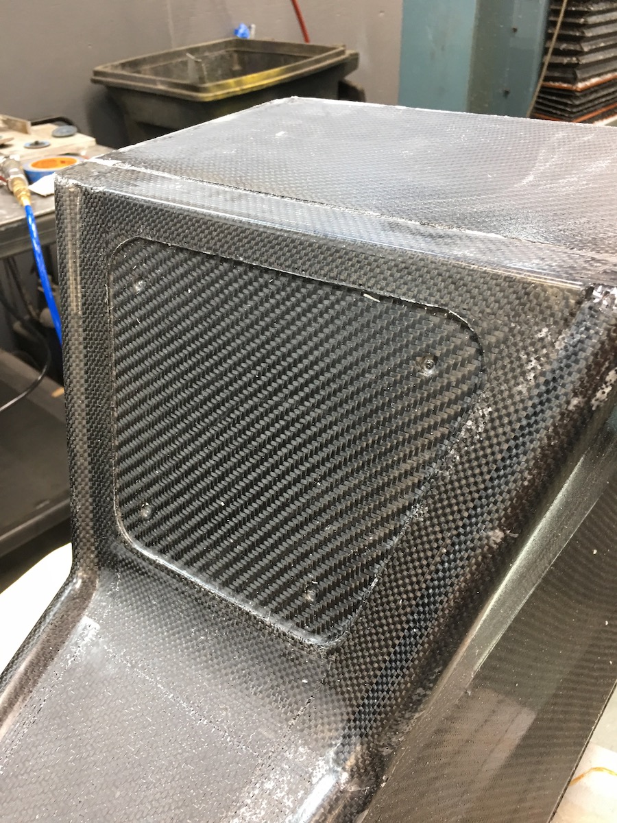
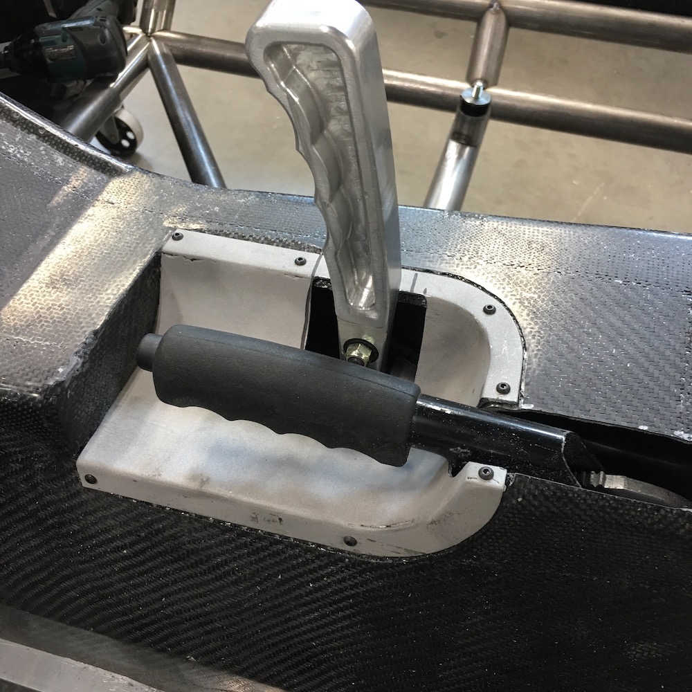
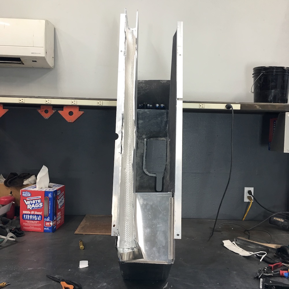
The cap that covers the hole where the shift lever and parking brake lever comes through should be a good start. I've made a mould of the aluminum piece and I'll get it all sanded smooth and such and then lay up a few layers of stuff on it and try the infusion method. I can always drop back to my original idea of just covering the aluminum piece and using it if the mould doesn't work out right. Thought about anodizing the piece but the sheet is 3003 and the filler is 6061 (I think...) so the different metals may not make for pretty finishes.


I'm gone for the weekend (tracking and teaching) so I'll get cracking on this probably Monday (or Tuesday, depending on how much of a recovery day I need). We shall see!
Apr 12, 2020
Playing with the center console again.
Got the two halves connected and am blending in all the seams and crap.
I don't like sanding!

Apr 25, 2020
Been busy around the house with stuff, a couple other side projects, trying to be social with my family, etc. - in other words, not been in the shop much.
Started priming and sanding and priming and sanding and sanding. First two layers went on okay - had too much pressure in my spray gun and made thick runny spots (more sanding). I was mainly trying to get a good layer down so I guess it worked:
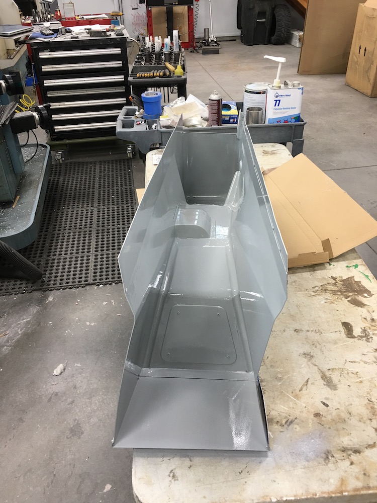
Then yesterday I got a regulator on my spray gun, got a nice even coat on everything and ended up with a good finish:
And guess what I get to do now - yup, SAND.
Hopefully either this afternoon or tomorrow I'll start cutting and laying in the carbon and fiberglass and making an attempt at vacuum infusion.
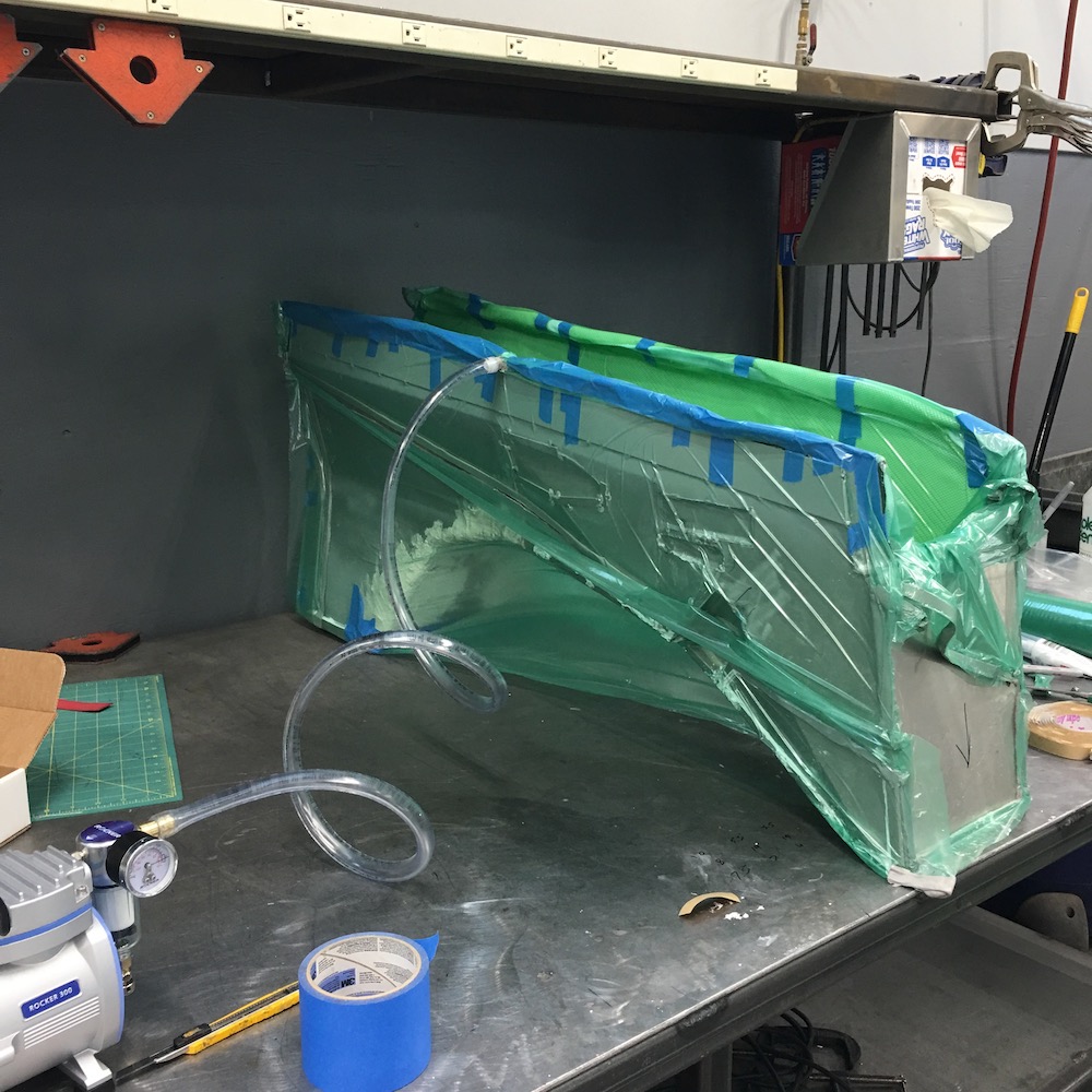
May 10, 2020
After much more sanding, a couple more coats of primer and lots of procrastination I decided to make heat shields and avoid the center console for a bit longer.
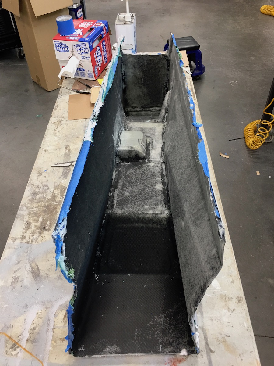
Yes, I'm intimidated by this one - never done vacuum infusion, haven't ever done a mold - especially a big surface one like this - and it's a one shot deal - the mold will be destroyed getting the console out. What could go wrong???
The smaller one still needs some hammer massaging where it meets the header cover - I'm starting to get this figured out too. Hit it here and it flexes there so hit it there and watch it flatten here then roll around the edges a bit and watch it all go flat, no, beat back around corners and now that other end doesn't fit. I really need a few proper body panel tools (may be a Harbor Freight run in my future).
Both of them will either get powder coated or (more than likely) covered in a layer of carbon. The back sides of both will be covered with the sticky backed aluminized heat shield stuff that I'm using in the header covers and the center console's water cover.
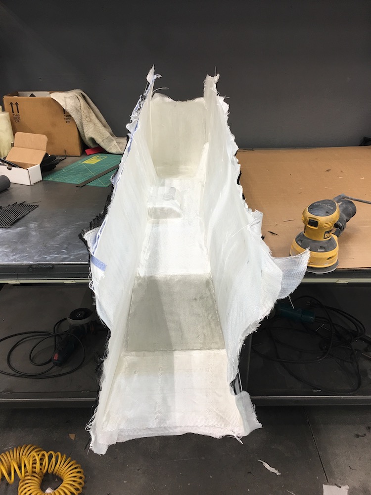
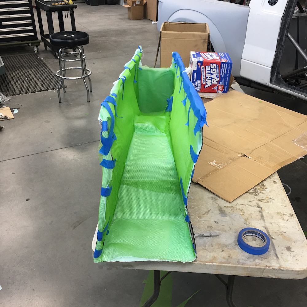
So I finally took the plunge yesterday and started laying up the center console. Started out making patterns.
Then got into cutting all the pieces. I'm about half way done.
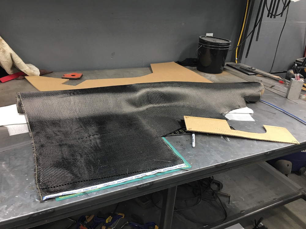
The rotary Olfa knife is just straight up bad ass for cutting this stuff. I also got a set of scissors just for cutting carbon from Fibreglast that work really well. Neither likes cutting the Kevlar threads present in some of the carbon that I have. That shit's tough.
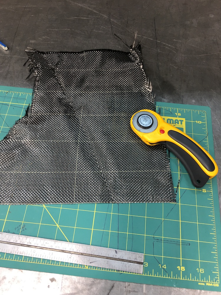
I'm taking my time and pulling out single strands to mark my straight edged lines. Once I've pulled a strand out I'll align the straight edge with it and zip it off with the Olfa knife. It's time consuming but I figure as much time as I already have in just the mold I may as well do this as perfectly as I am capable of (results will define "perfect").
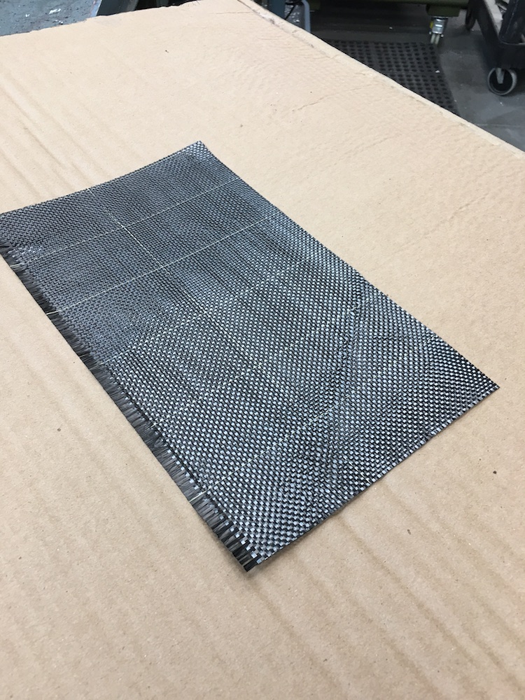
Lay up will be two layers of carbon weave - outer is 3K 2x2 twill, second will be either the same (on the sides) or some plain weave 6K (maybe? - it's heavier/stiffer) that I've had forever and then there'll be four layers of 4 oz fiberglass cloth.
The corners and edges all get a piece of 2" woven carbon fiber tape. It'll (supposedly - at least it's my plan) cover all the ragged edges between the pieces and should give a unique look to the piece too.
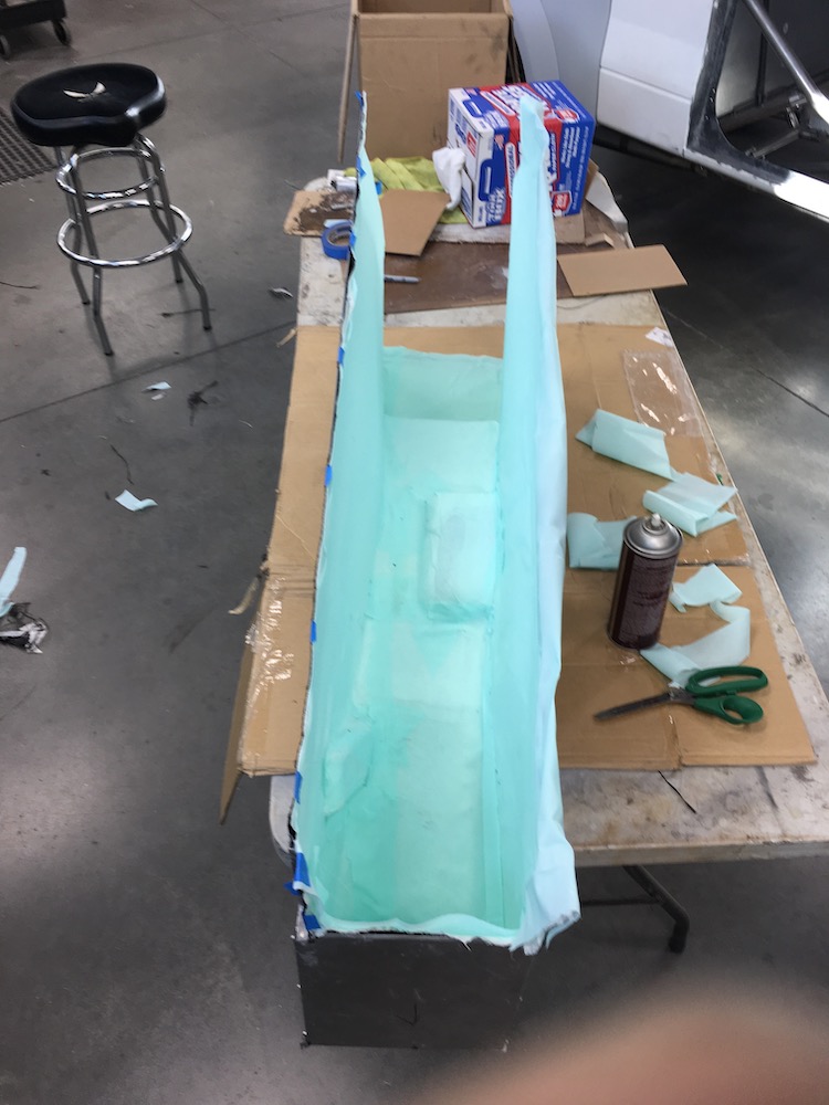
That little strip that looks crooked actually has a bubble under it. It lays down flat. Heck, all the unstraight lines are where the fabric's pulled away from the mold (using Super 77 to stick it all down).
Once everything's cut and fitted I'll start working in the resin feeding tubing/sheeting stuff, get the vacuum bag on it, seal it up and then we'll see what happens.
May 10, 2020
bdkw1
Wait, super 77? Your glueing them strips in? Do you have some sort of mold release in there? How do you plan on getting it out? Magic?
Me
Yes, there's mold release and the 77 doesn't stick well at all. As soon as the solvent evaporates instead of sticking it wants to slide. The first layer was a bitch to get laid down. Each additional layer helps hold shape and keep it in place.
Definitely gonna need some magic to get it out. Like I said, disposable mold.
May 13, 2020
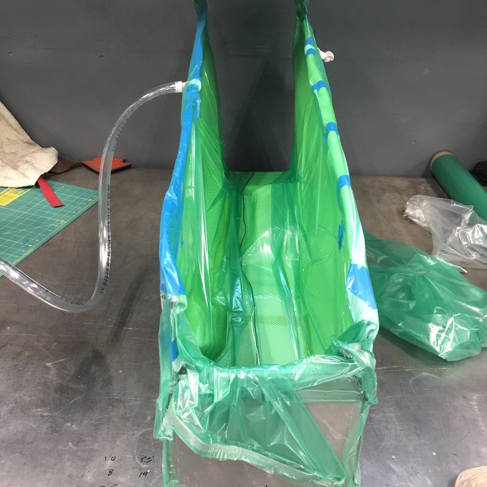
Got all the glass installed today:
Next is the peel ply - it's the release layer:
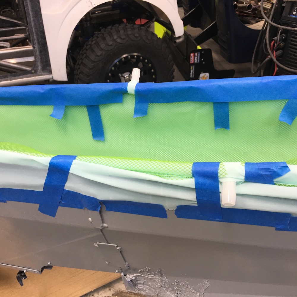
This is the infusion mesh. It goes down over the peel ply and then the bagging goes over that. The mesh allows for the resin to flow evenly to all points.
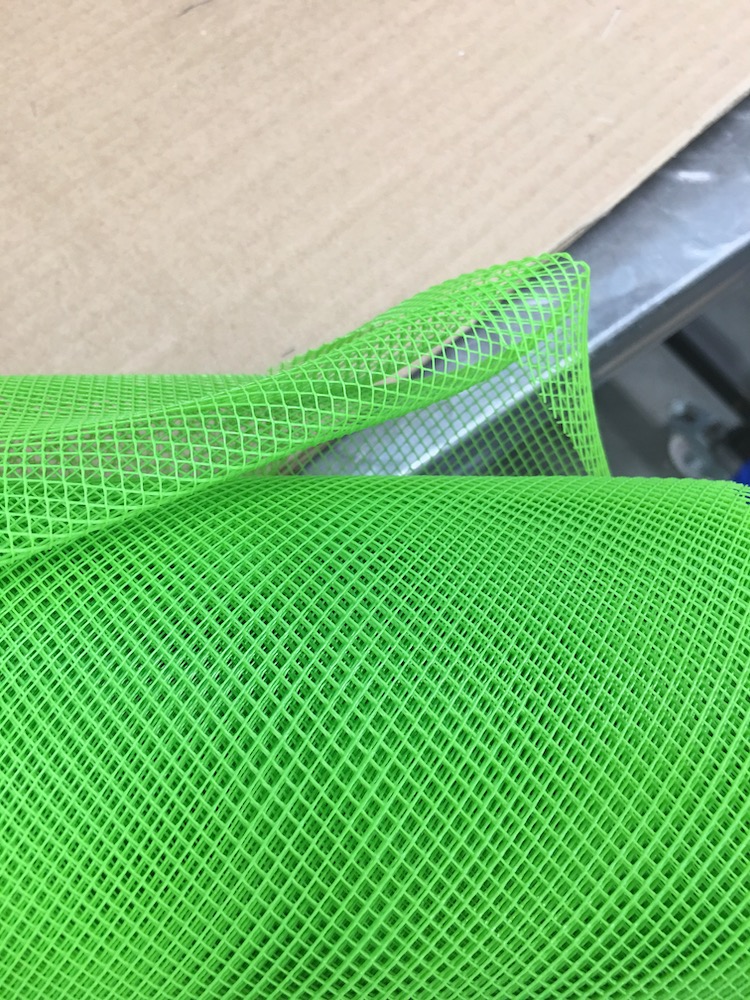
I'll get it set up with a feeder line on the front, back and one edge and then the draw line will be on the other edge. I'll pull a vacuum on the draw side with the feeder side shut off and find any leaks. One I'm satisifed I'll do a leak down and let it sit. If that passes I'll mix up resin and infuse it into the console.
One step closer.
May 14, 2020
Leaks.
Bag leaks.
PITA!
I'll hopefully find them tomorrow (or may rebag it - not quite happy with the way it turned out).
Off subject but info/thoughts needed/wanted:Need to cool the supercharged air. There is no intercooler presently.
Speaking with Rat, suggestion of this setup: MR2 intercooler to air.
The Wizard has mentioned water to air but that's gonna require an air to water radiator to cool the intercooler water which means another system.
What about mounting the linked above intercooler flat above (in the area of) the engine and putting a fan or two behind it? That would pull ambient air from behind the cab and blow the hot air on down below the bed liner/cover (think TT style cover).
May 18, 2020
Flea-Bay MR2 intercooler on the way.
The bagging tape doesn't stick to the silicone I used to seal seams so I scraped it off and got the bag stuck down.
Once I did that I started working around the edges.
Suddenly the pump changed sound, the bagging drew in and I started hearing itty bitty snakes hissing in half a dozen places.
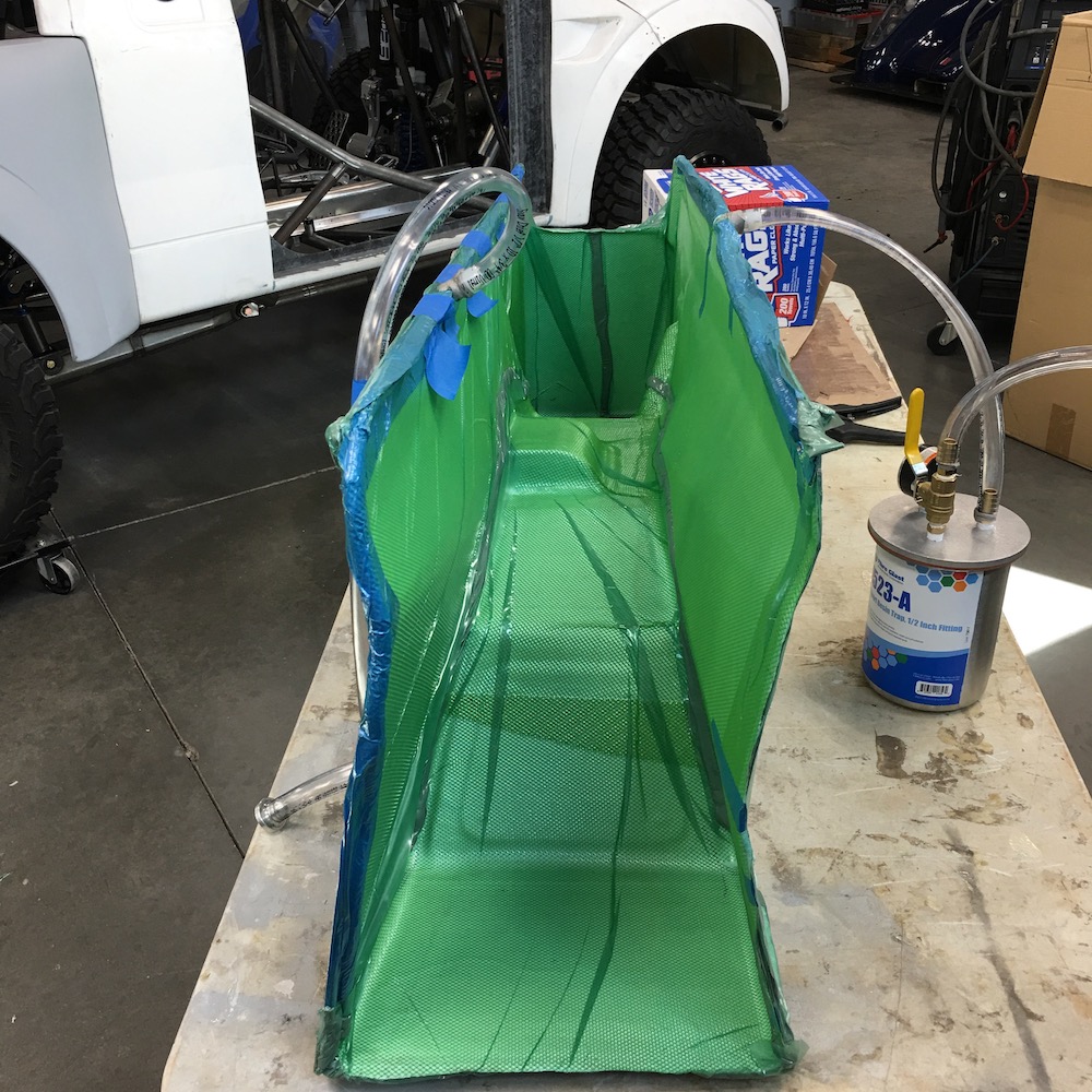
Tackled each one and got a pull of about two thirds of a full seal.
Got the wrong type of stethoscope so I can't use it and my hearing sucks so... Had to laugh - as I'm sliding my ear along seams and edges the sound of my hair dragging made more noise than some of the leaks. Missing the pony tail - was able to keep it up and wouldn't have had to deal with it. The fan in the computer box on the mill is old, tired and makes a sound similar to the hissing so that didn't help either.
I'm tempted to go down to the hardware store and buy a can of that sealing spray the guy makes a screen door into a boat bottom with and cover the damn thing with it to find those final teeeeennnnyyyy tiiiinnnnyyyy leaks.
Got an off roading weekend planned so this may wait until Monday or I may get out of Sunday's drive - but not sure I want to. I mean, pass up a chance to go play in the dirt? Who does that?
bdkw1
Flex seal that bitch!
Me
Yeah, the change in pitch from the pump is a good sign. Used to listen for that with the vacuum fixtures for the mill.
I think I'm gonna hit the hardware store and give the Flex Seal a shot.
May 19, 2020
plkracer
Piece of hose up to your ear would probably help identify the location.
We use the blue speed tape everywhere for bagging carbon fiber. Hard to find something that sticks to teflon film.
Me
A can of Flex Seal has been procured but a desert ride has popped up and that shall thwart my efforts for a bit.
Tube in the ear... could pull one off the stethoscope I have. Already thought about making a little reverse megaphone that I can replace the sensor part with.
May 22, 2020
Stepped away from the bagging for a minute. Three days of chasing invisible yet hearable (sort of) hisses and leaks is taking its toll. I think I've almost got it now, though.
I got to the point on Monday night that I'd said screw it and was going to go ahead and infuse and look for any bubbles and fix as it's infusing but the epoxy had gelled up and wasn't going to work. WTF? It's a brand new just opened can. Had to call Fibreglast and ask what was up with a new gallon of resin being stiff and was told "it's cold, just warm it up". A bucket or four of soaking the can in hot water and whaddya know, it's clear, has low viscosity and looks like it's supposed to work now.
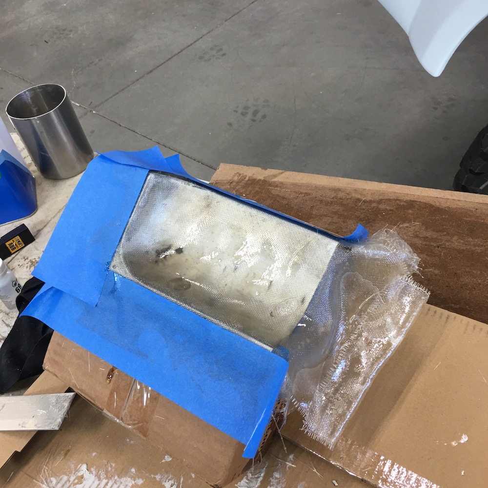
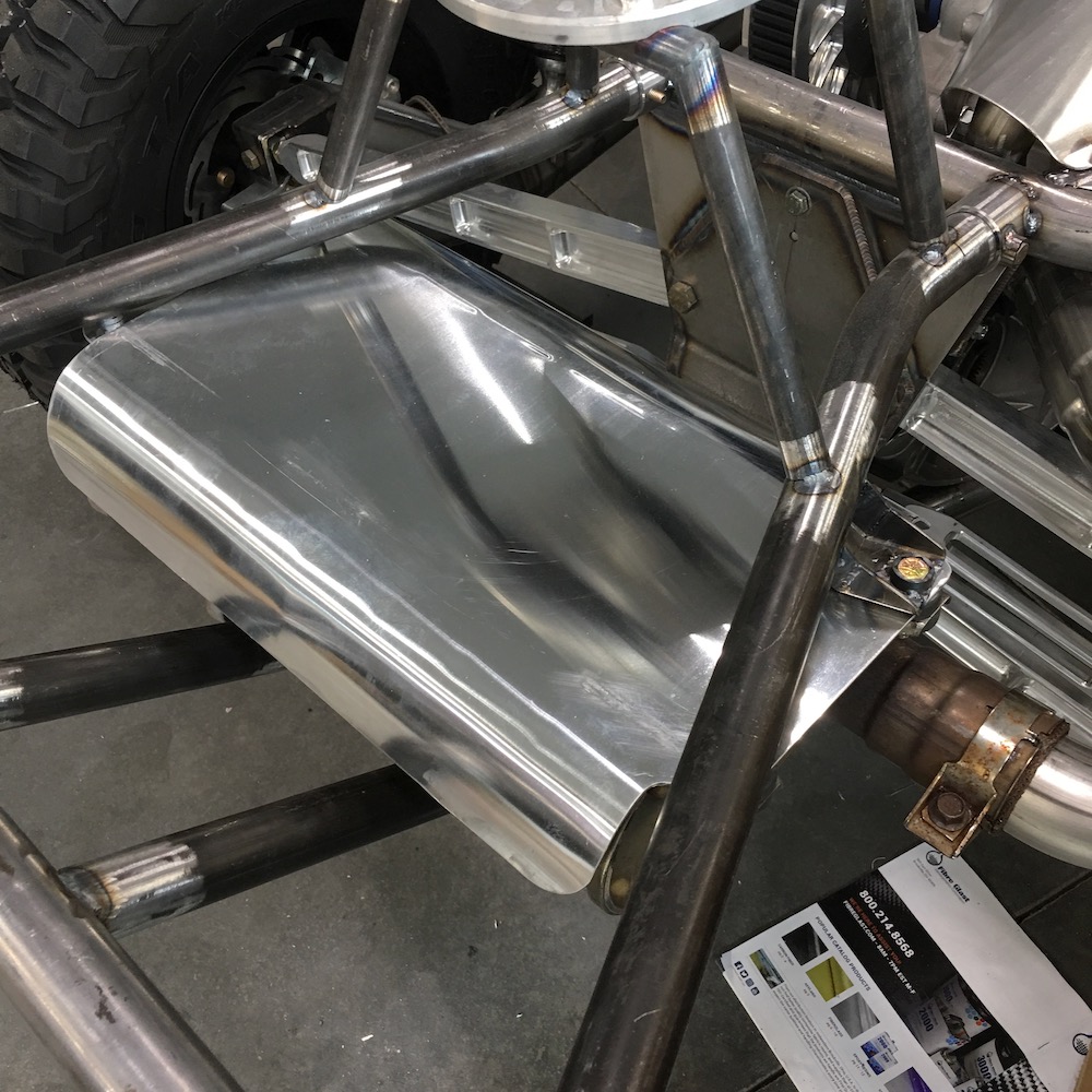
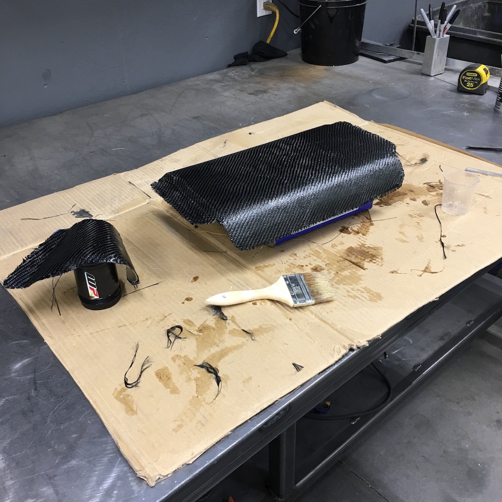
So I decided to do a little cosmetic carbon and cover the two heat shields that I've done for the exhaust.
First, cover them in carbon. Two layers held in place with Super77 adhesive:

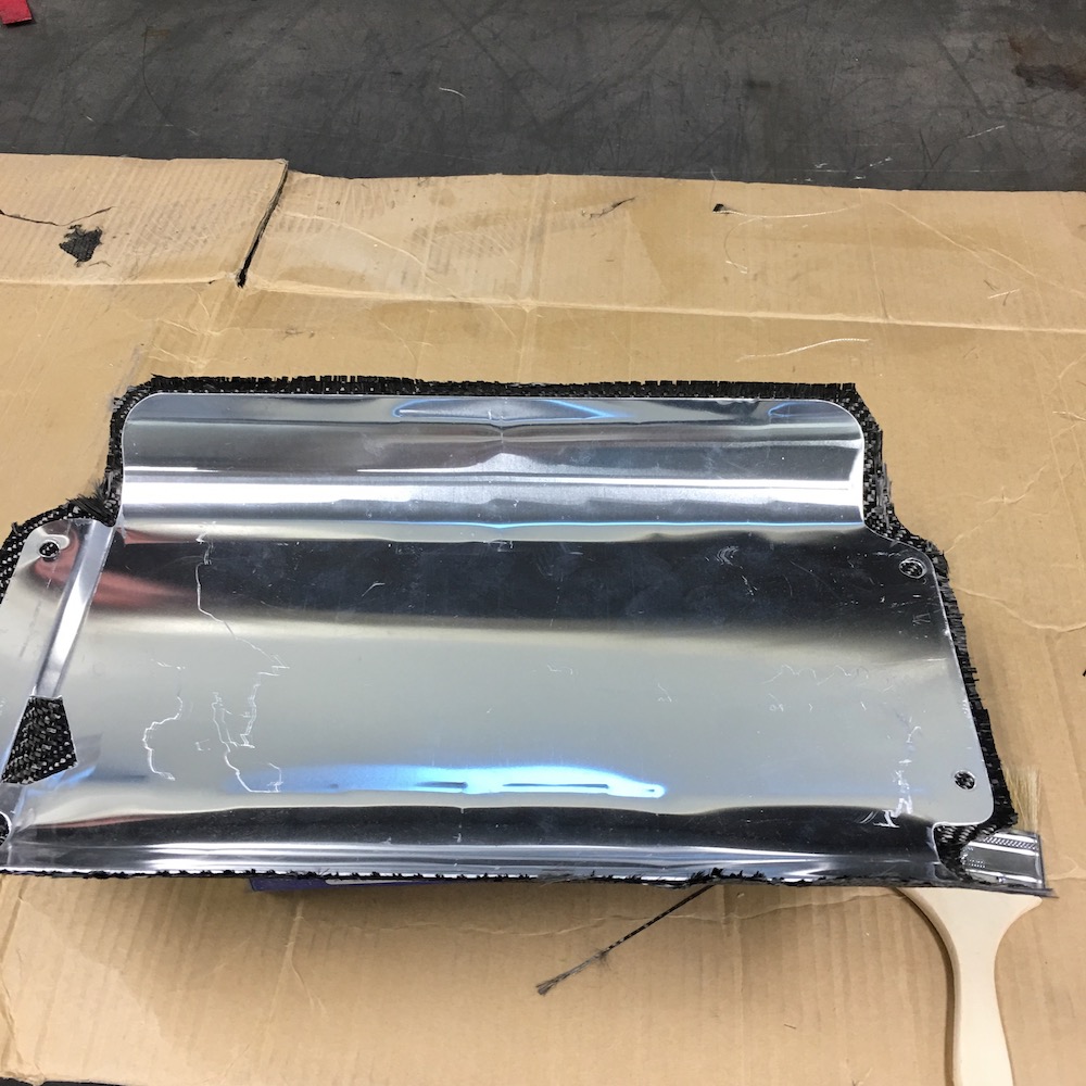
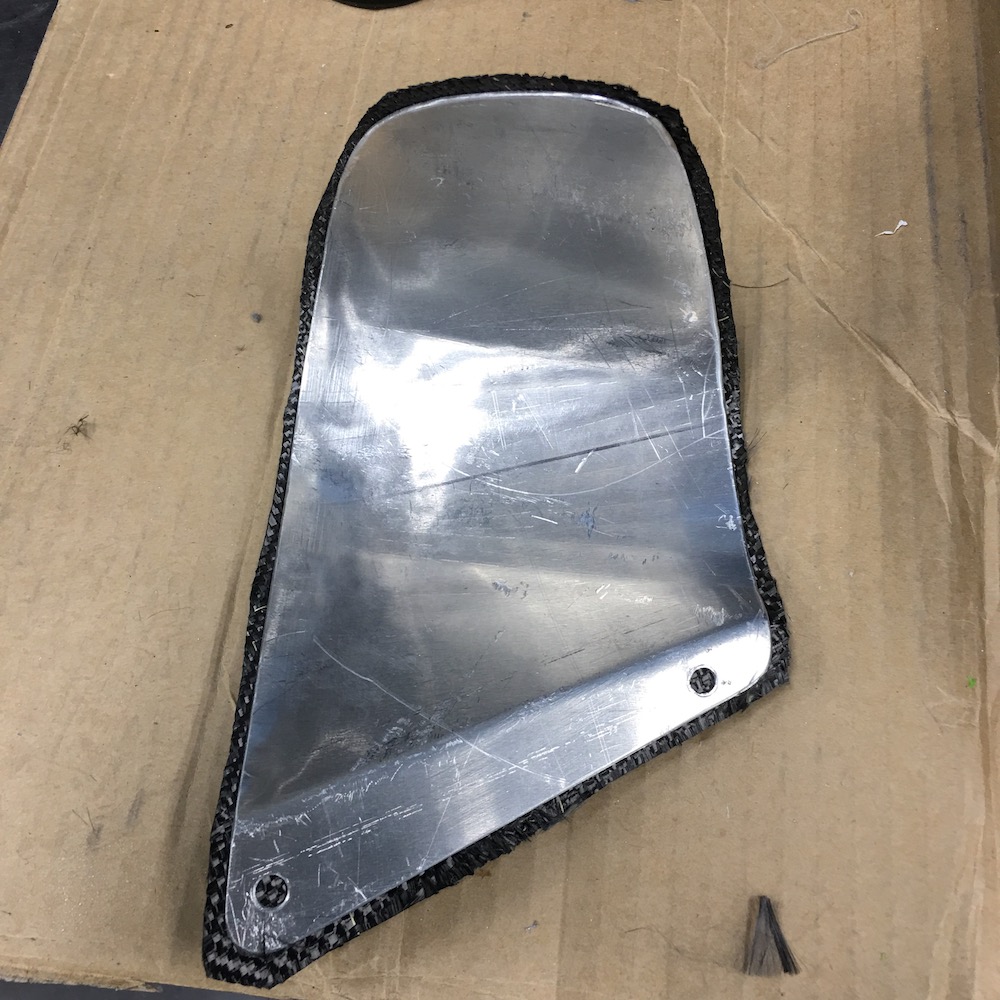
Then wet them up with polyester resin and let them sit for a few hours. I purposely left them "raw" and didn't bag them for a smooth finish. It matches the shields that I made for the header section of the exhaust.
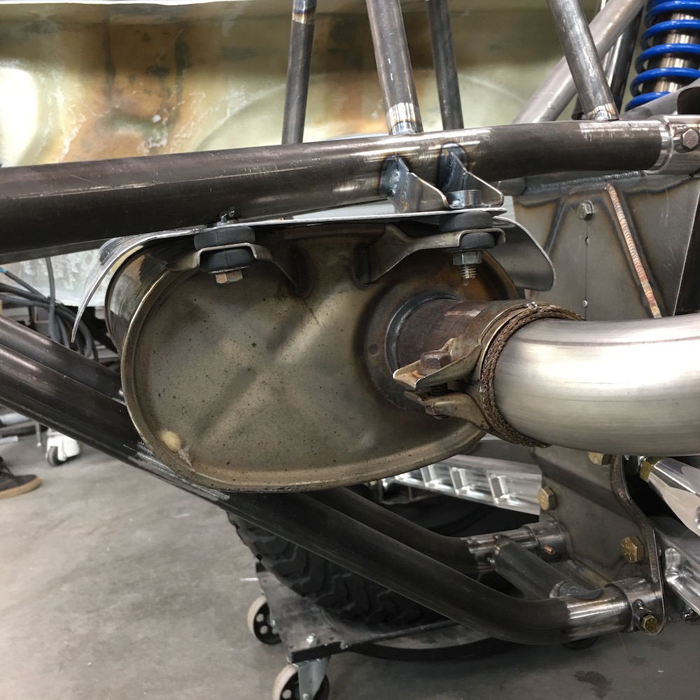
Once they were dry I trimmed the edges and the back sides of them, that is next to the exhaust, got some of the aluminized fiberglass heat shielding installed (box says the stuff's good to 1,750F (954C) along with the sealing tape that's recommended:
They turned out looking pretty darned sweet (or at least I'm happy with the results):
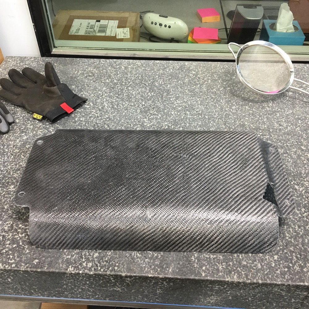
Then they got put in their new homes and I think they're happy there.

Gonna tackle the bagging project again today. Hopefully I'll be mixing resin.
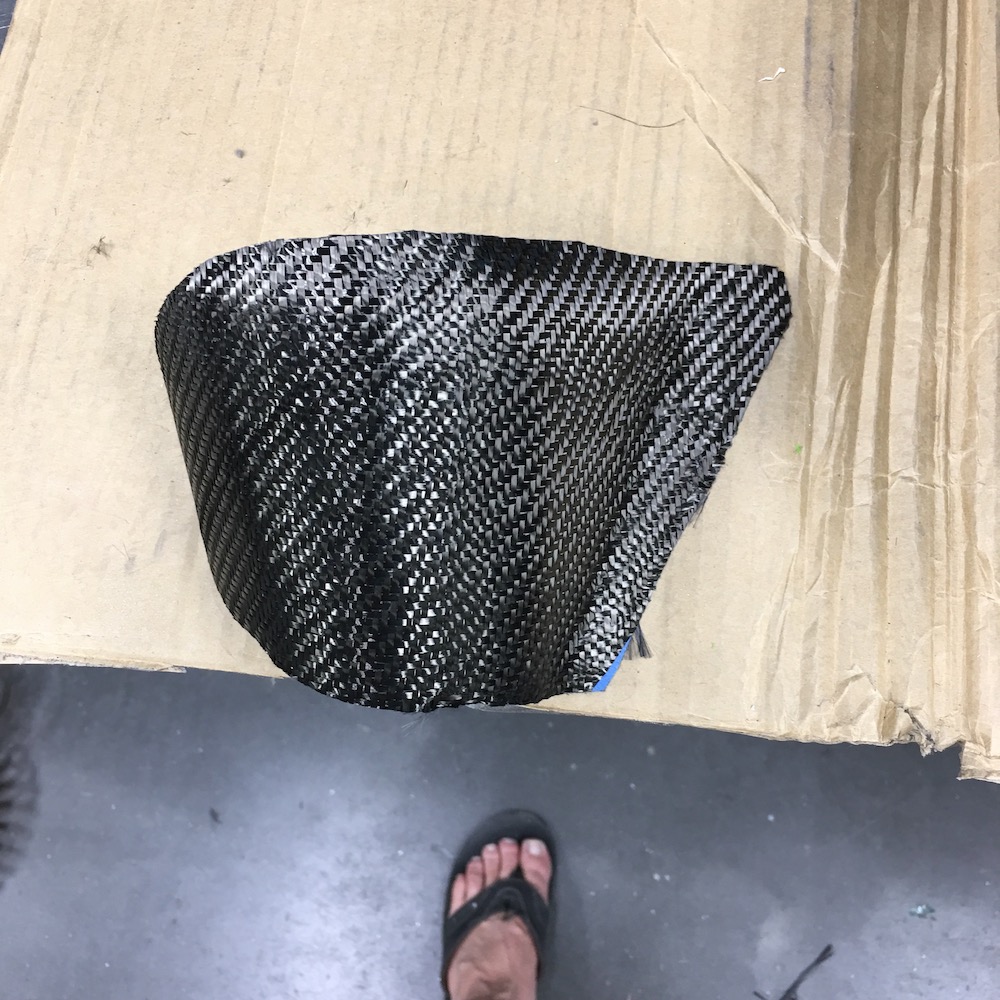
May 23, 2020
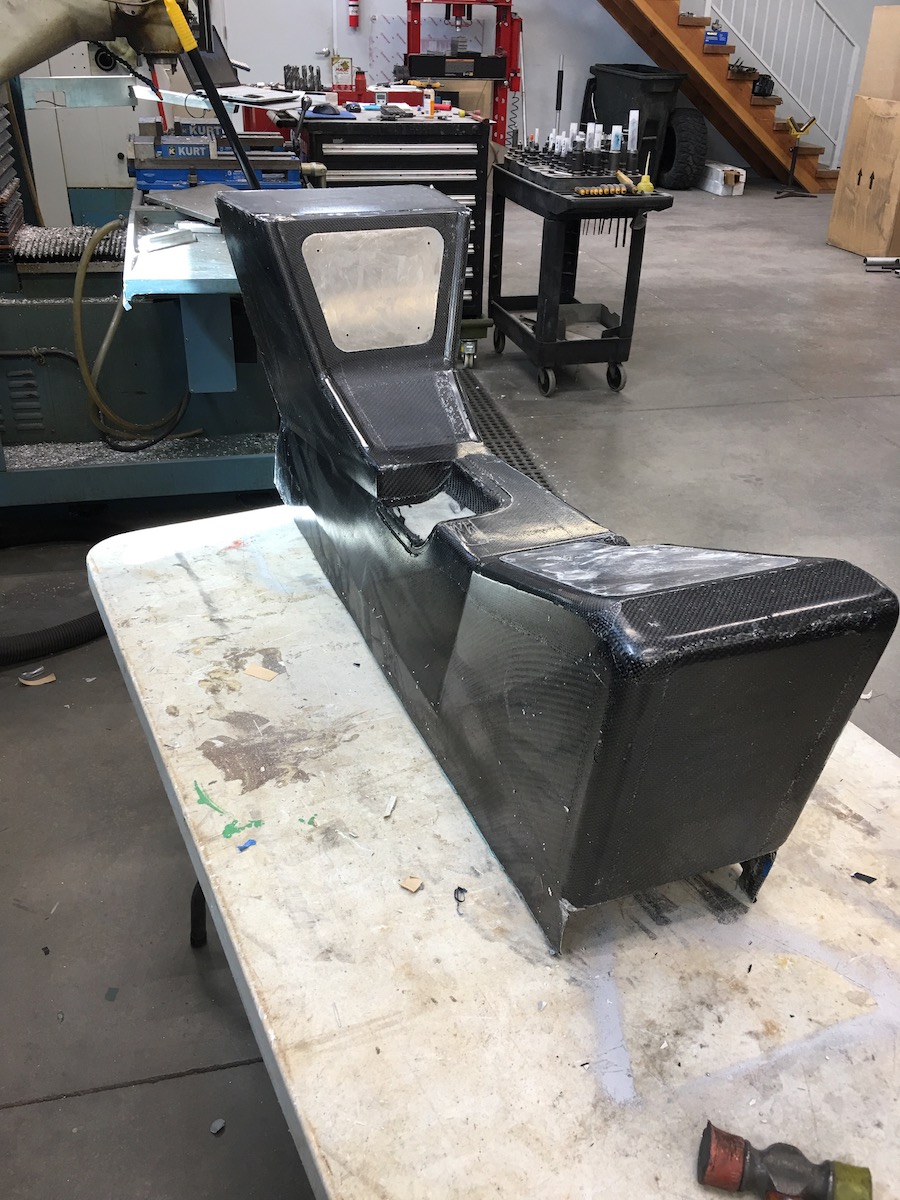
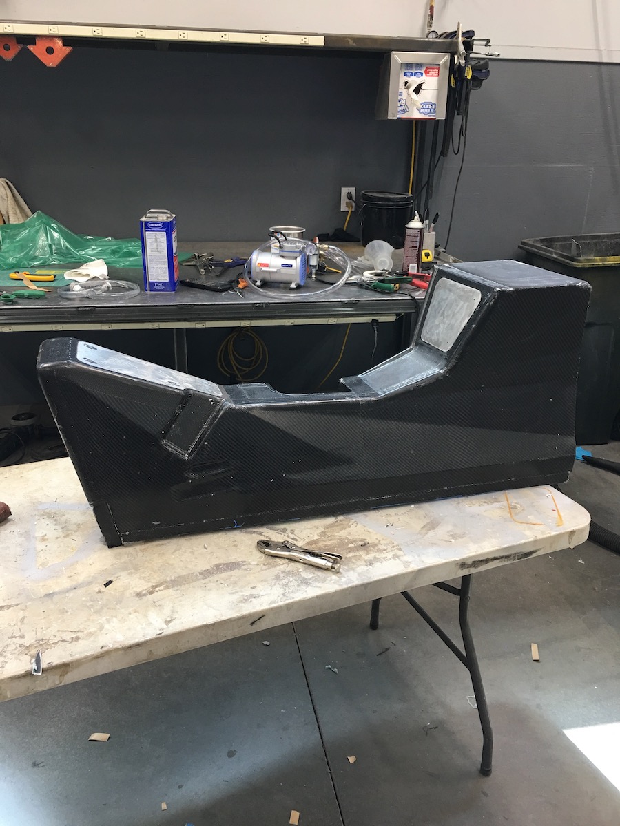
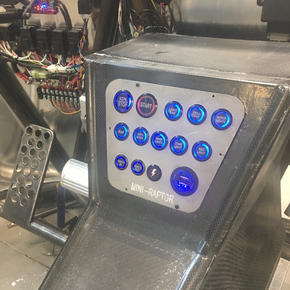
And I have a console!
There's porosity, there are areas that will need to get filled and sanded, there are different textures and surfaces but overall I'm very pleased with the results. I'll be able to cover up/fix most of the defects with some epoxy and a few coats of matte finish polyester. Considering the size of the part and all the things I did wrong I won't complain. The dash will turn out much better.
The two panels and the insert where the shifter/e-brake are will get covered in carbon also and then screwed in place. I'm using some large scale RC hinges for the door on the glove box. I also have to finish the box - needs a bottom and front and sealed up to the console.
Button layout has been mucked about with - will figure it out and then cut them out on the mill.
It weighs around 4 lbs.

May 28, 2020
Glove box is in.
Bottom and front with latch:

Latch pin holder detail. Yeah, it's billet - why not?
Heck, to make it even more special, it's 7075 so it's even stronger. Ooooooo, aaaahhhh... (it was a spare piece of stuff that fit the bill.)
Kinda looks like something you'd find in an airplane with all the rivets. flyerrider inspired the airplane aspect with the suggestion of the glue used to secure it to the composite. Same stuff I used on the hood - some mystical, magical aero epoxy that they put planes together with and you get from McMaster.
Pay no attention to the little plate behind the bolts covering up the screwed up holes. I'll tell everyone it's a strengthening plate.
Epoxied in place, ready to race. (hey, it rhymes)
Today I'll work on getting the two mounting strips that hold the console in place in the cabin and then I'll focus on the insert that the shifter and e-brake go through. After that it's get the button panel in place.
May 29, 2020
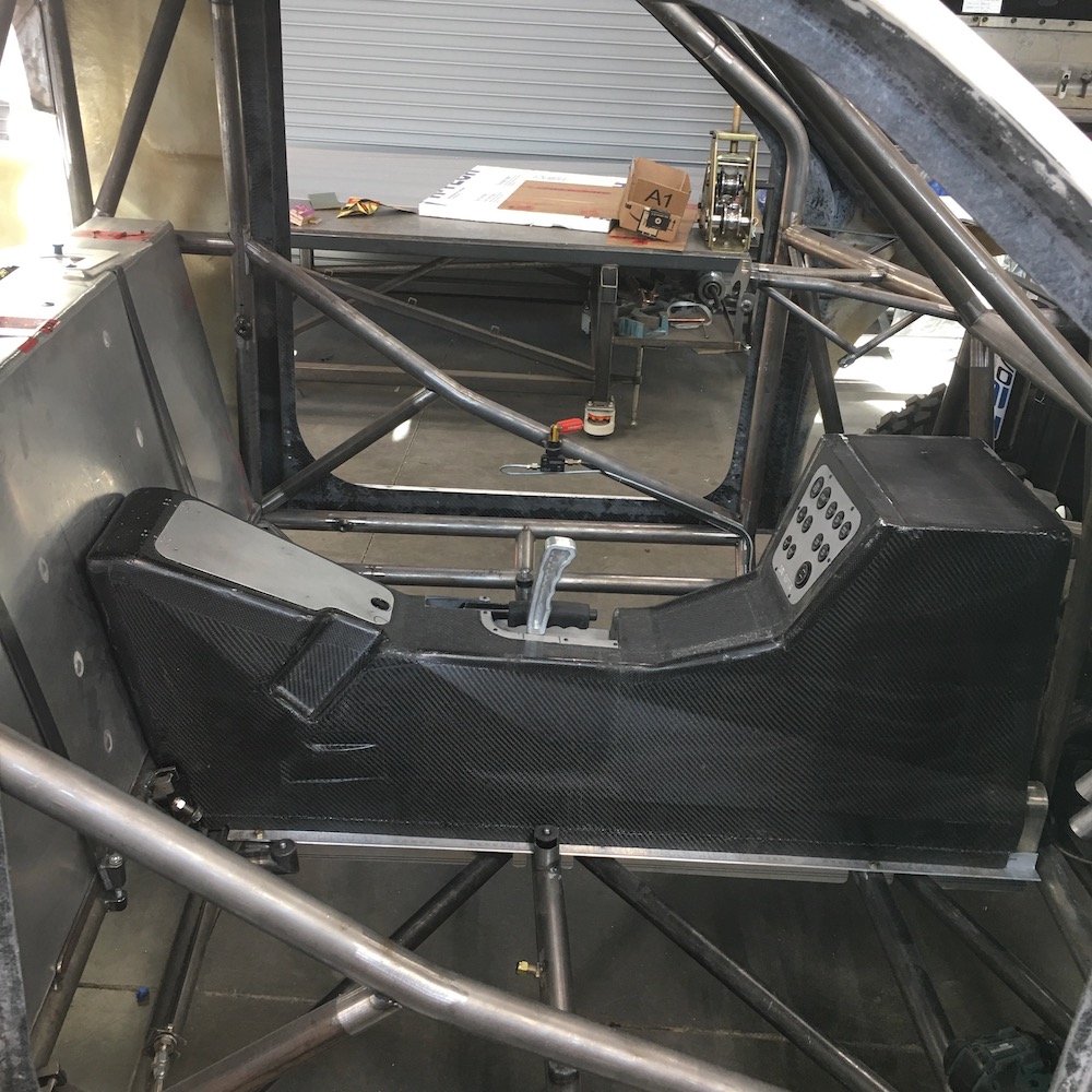
Center console is coming along.
Glove box is complete with the exception of some sort of "lid ejection system" so it'll pop open when I push the button.I have a couple thoughts that I'll pursue:
1) Some sort of small R/C off road shock that's attached to the hinges since they're large scale R/C aircraft hinges - already have mounting lugs.
B) Some sort of spring system that sits on the little ball that the push button latch attaches to. It'll just push the button piece up, off the ball. Simple, easy, not sure how I'd keep the spring in place - thinking some sort of collar that slides.
We shall see...
I still need to do a bit of trim work on the console and the two side rails that attach it to the floor need to be adhered to it.
Anyhow, pix:
Originally I was thinking that the panels would get covered in carbon and blend in but now that I see them on the console with the bead blasted finish, I'm thinking I'll leave them this way (get them clear powder coated). I like the contrast between the aluminum and carbon.
This lid will probably get remade today - I get the feeling it'll take less time than trying to weld fill the six holes. The little upside down u shaped mark is where I'll put a finger grab if I can't figure out an opening spring system. I have to laugh at it smiling at me each time I look at it.
It's a happy little cover.
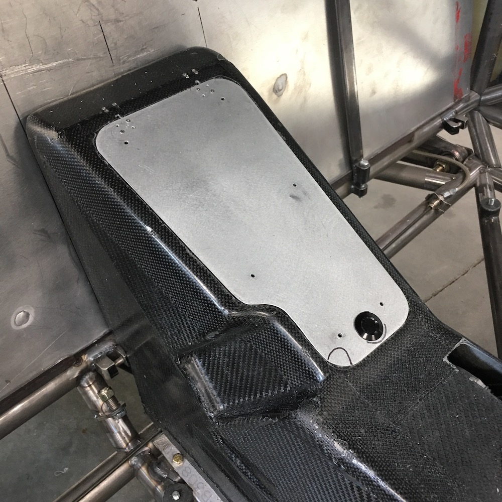
This is panel number two.
First one was coming along just fine until the mill opened up the last hole. I'd already cut all the button holes but the smaller ones were a few thou too small so I went back through and reprogrammed them. It walked through all of them, skimming off just enough that the buttons dropped right in and then it got to the last hole and stuck the bit off out in nowhere land, outside of the hole. Turns out that when you miss the 3 in .375 for the radius you end up with a hole that's suddenly twice as large as it's supposed to be. Off to the scrap bin that piece went.
Second panel hole cutting went perfectly. Then I did the mounting bolt holes and of course the LAST hole ends up being off to the right by .200" - fortunately it's just a small flaw and darned near covered by the button head cap screw.
I did the Mini-Raptor engraving, thought the panel was just fine and took it to the bead blaster. Hey, where'd the Mini-Raptor logo go?
Back in the mill, get things all set up, hit go and WTF? Why did it engrave deeper? Obviously I didn't get the panel fully seated in the vice. Crap. I see panel #3 in my future - fortunately I've saved the correctly dimensioned program and it's actually quite easy to whip this piece out.
Still need some trimming of the slot where the e-brake fits through the console. It needs to be opened up and Glock mentioned doing some sort of trim around the hole - I have just the right stuff for it too.
The hole where the shifter comes through is a bit of an eye sore - it need to be as wide (front to rear as you see in the pic) as it is to the lever has enough room to swing but my highly calculated thumb measurement must not have been calibrated correctly and the hole ended up being about half an inch too far towards the e-brake lever so I've a large, ugly hole in the middle of a piece that has waaaaaayyyyyy too much time invested in it - and it still needs clean up. I'll wing it and figure out some cosmetic fix.
More to come. Company that's been here for the past week went back to Hell, er, Ohio, this morning so I have more free time in the shop. I plan on hermeting myself there the remainder of the week.
Thinking the next part on the Mini-Raptor that's going to get attention is mounting the intercooler and redoing the plenum box. Once that's plumbed in it's wire harness time. Starting this beastie is getting closer.
May 31, 2020
Okay, where was I in updating this thread - only trying to keep three of them going (here, FB & IG)
The center console is done with the exception of an ejection spring for the glove box latch and then a few coats of clear polyurethane. There will probably be some sort of fasteners done between the flat top of the console and the dash (they'll fit together, I hope).
I got the coolant tubing tunnel insulated and installed - twice... First time I used an incorrect hole while riveting it in place. Made the front of the console sit up proud about .250". The tunnel fits perfectly over the coolant lines. I'm pleased with the results.
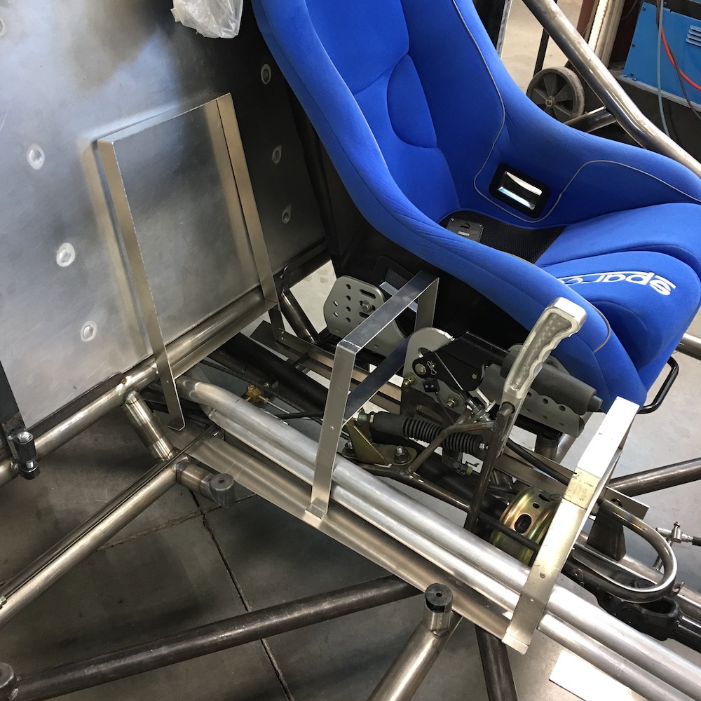
After getting the console in and set it was time to see if the seats fit and yes, yes they do! Woo hoo! All the crap and such I went through on the passenger's side, for clearance, worked perfectly. The seat moves fore/aft w/o touching the console. Yippee!!!
I also got the steering column installed - it goes right through the side of the console. I was off by about .125 so no complaints considering I had to tie two points together through a black plane that's not parallel or perpendicular to anything. I also now have an idea of what the dash is gonna look like. I'll get back to that after the next step, below.
Time to get the intake system plumbed and working. The intercooler is an air to air setup and will have a puller fan underneath it that will be on a pressure switch. Anytime there's boost the fan will come on.
I need to mod the plenum box. The inlet tube needs to be moved from it's present place on the bottom to the top and the blow off valve needs to get relocated - it already was, as it hit the back of the cab.
I have to make a cradle for the intercooler that is attached to the engine as the power plant's all rubber mounted so mounting it to the chassis wouldn't be a good thing.
June 5, 2020
Intake system is finished other than a few small plumbing lines and an air filtration system. I'm thinking that I'll do something similar to what I did on the Dez II and use a paper automotive filter (like an E-450). Readily available at your local Vato Zone or Meth Boys, inexpensive and works well. I'll have to make a box and do a bit of tubing to get to the supercharger but that shouldn't be an issue. It'll look like some of the cold intake systems you see on the rice burner cars.
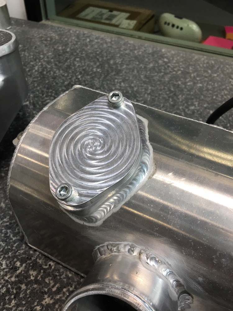
Finished plenum box. Had to close off the original intake tube that's on the bottom of the box, move it to the top, relocate the blow off valve and block off the original boss where the blow off valve used to live.
Not unhappy with my welding. The intake tube isn't all that pretty but it's good and leak free.

Managed to, at least partially, channel TALON and my blow off valve relocation welding is definitely looking better than some of the other stuff I've melted together (block off plate on bottom, that I'm not gonna show to anyone, would be a prime example. Thank goodness for grinders!!!)
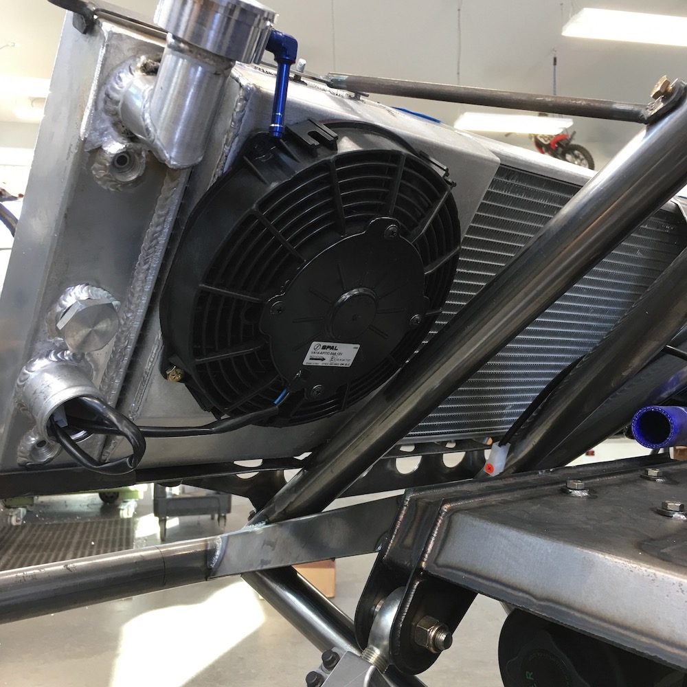
My welds may not be pretty but my block off plate is! It's gonna look even better after anodizing. My God there's gonna be a massive amount of anodizing happening.
Spal fan in place. Ended up going with the 7.5" diameter fan and let it hang over the edges just a tad (intercooler is 7.25" wide). The Spal I chose is rated at 500 cfm. They also make, in the same 7.5", a 437 cfm but why go with less flow? I bumped up from the idea of using a 6.5" fan that fit "better" because it only pulled 325 cfm. I want as much air flow over the cooling section as possible.
Like the gnarly single tube in the front of the pic? I don't have a bender for that size tubing so it got placed in a vice and yanked on ever half inch or so. It's hidden from sight unless you're looking for it and a bit of powder coating will make it even less noticeable.
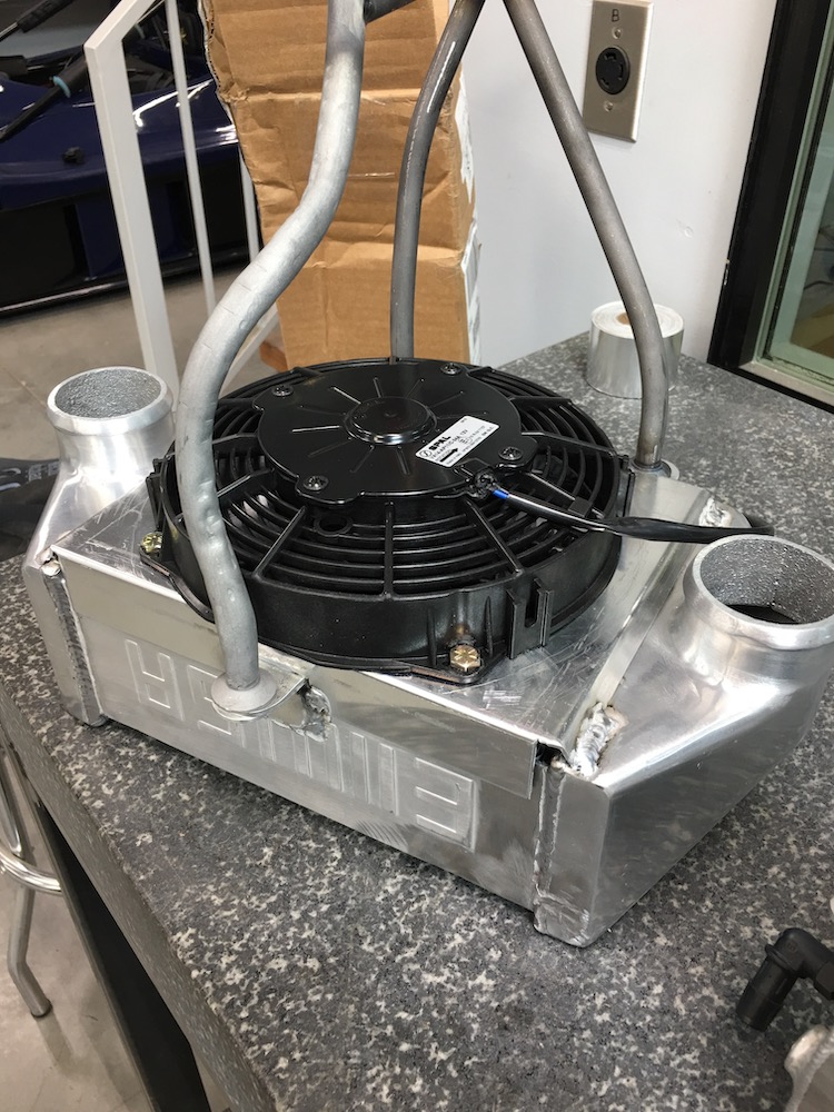
System in place. I'm impressed with how well supported the intercooler ended up being once I got the plumbing attached. The three legged contraption that holds it to the engine does a great job of not letting it move fore/aft but it's not so good left/right. Fortunately, with the aluminum intake tube and the really short coupling between the intercooler and the intake plenum, the whole system stiffened up really nicely.

And now that I've finished this update it's time to head down to the shop and start making electron paths. (wiring). There's a really good chance this thing will fire up next week. The chassis is nowhere near ready to drive but I can check and see that all systems are working.
Jun 6, 2020
Wiring has begun. Spent a couple of hours with a sharpie, wire schematic and figuring out where all the connectors on the harness went/what they did and marking them. Once I got that all dialed in I laid the harness on top of the engine, plugged everything in and other than one temporary twisted pair of wires coming apart and giving me a code, when I turned the key for the first time, no smoke was let out. WOO HOO!!!!
Now it's time to pull this harness apart and start routing lots and lots of little wires.
I see a running power plant by the end of next week.
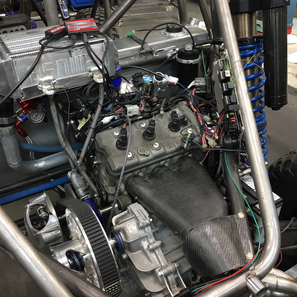
One Yamaha Nytro nervous system, partially peeled and getting prepped for service.
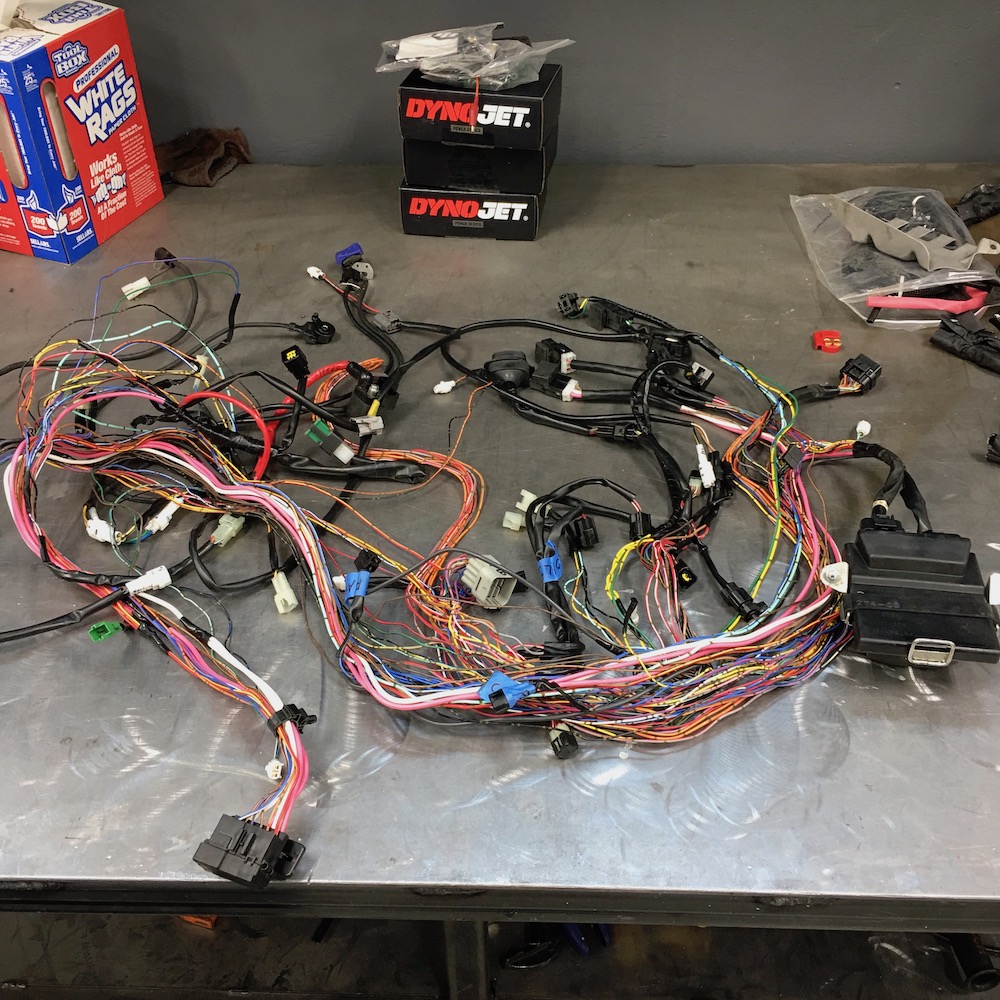
Weight savings! Begone extra wires, begone!
Stripped and ready to drop back in.
I've isolated each sensor, set each circuit off and tried to get the harness a bit more cleaned up as far as wire routing - lots of stuff was wrapped among other wires and pulling on one end would make stuff else where and the likes. Now it's all individually set aside.
I'll hook everything back up, probably toss in the starting circuit this time too and see if the engine turns over. No fire, just spins. If that works and I have no codes thrown I'll start making the harness fit.
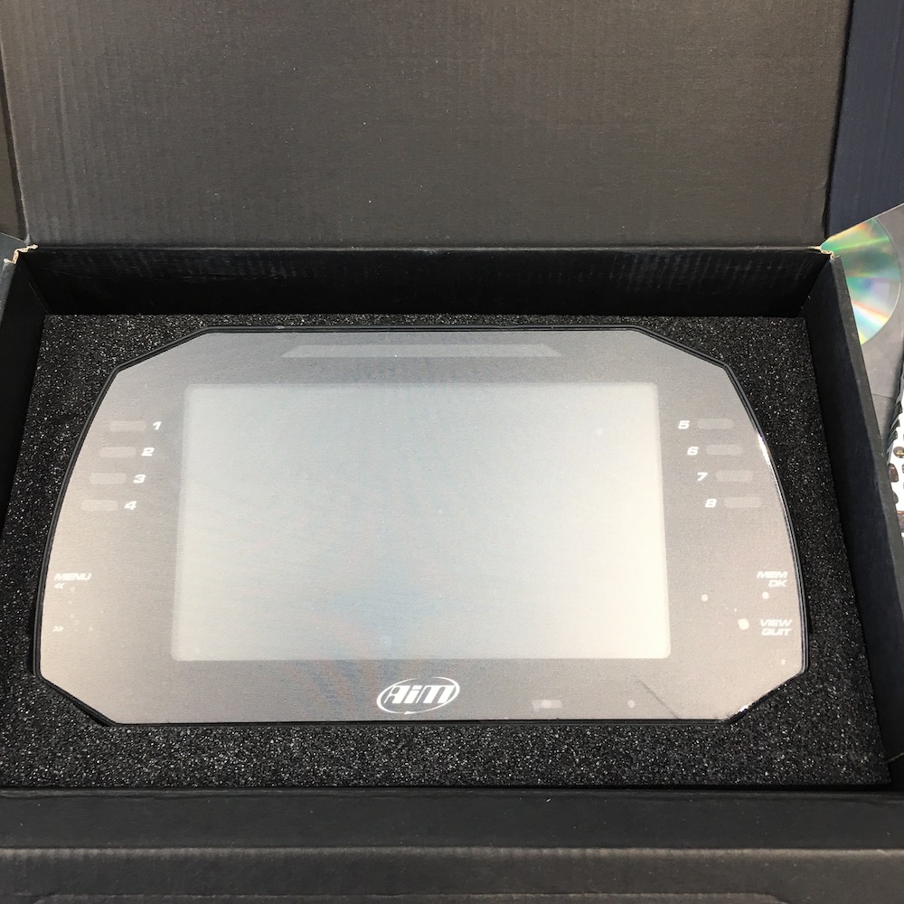
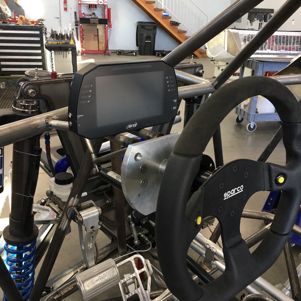
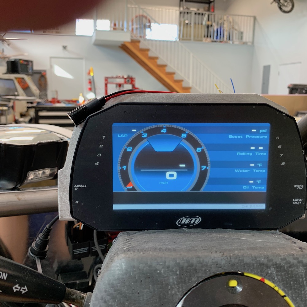
I'm thinking that the OEM dash and the DynoJet tuning stuff is going to end up in it's own little box on the back of the chassis so I can do all my tuning right there instead of having to go back and forth from the cab to the back of the Mini-Raptor. I have an AiM dash that's gonna piggyback on the Yamaha system and give me all my pertinent info.
June 14, 2020
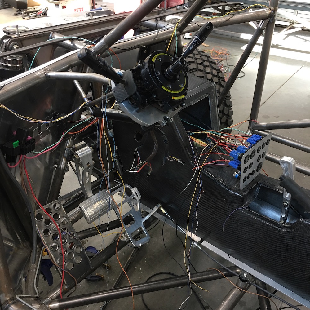
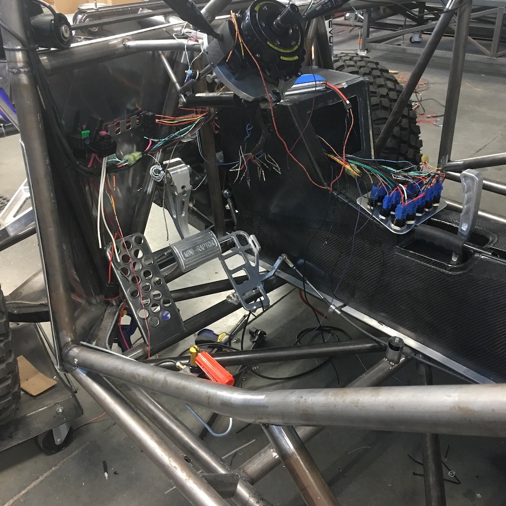
Wiring time!
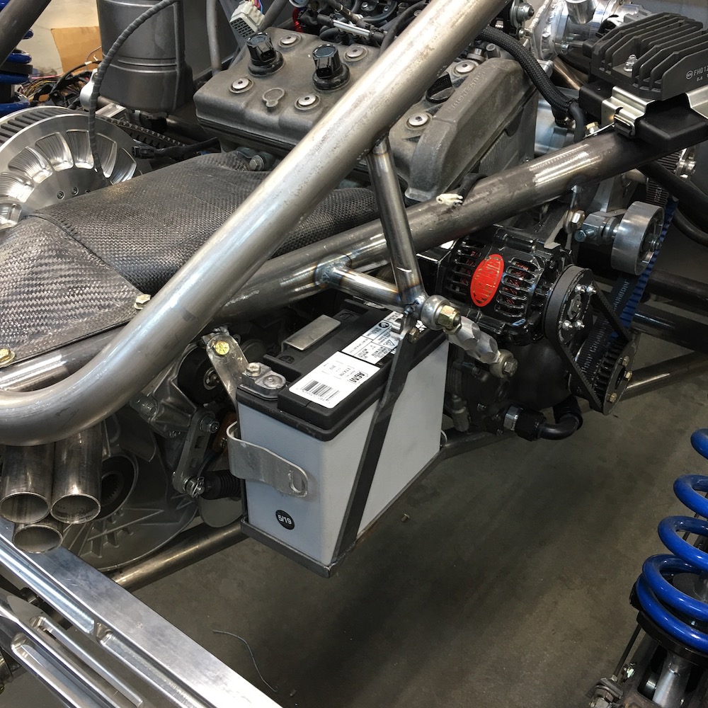
Had to get naked to work on her:
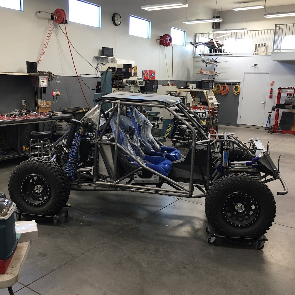
Then it was time to mount the battery. It's tucked away in a safe place, away from most heat sources (exhaust is covered but fairly close):
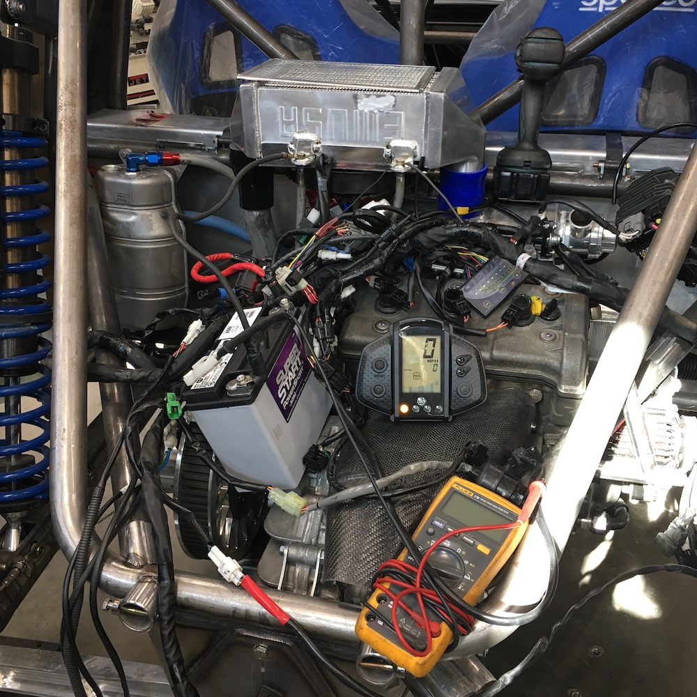
Once the battery was located it was time to take the pile of wire off the work bench and throw it on top of the engine and see what can be done with it.
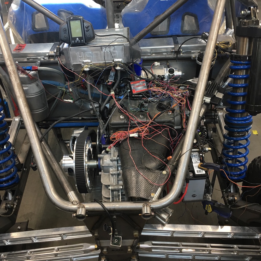
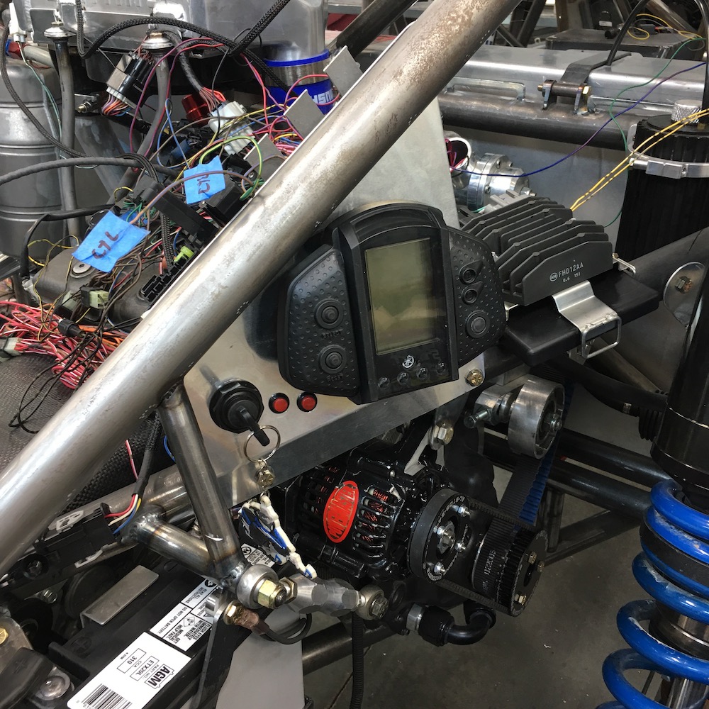
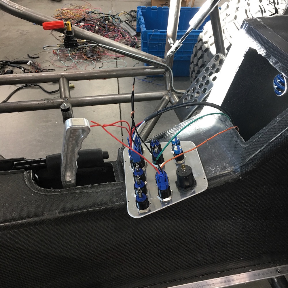
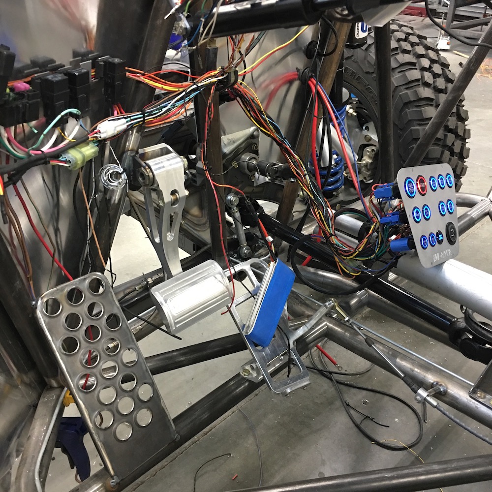
I decided to mount all the sled electronics back with the engine. It'll make it easier to control (especially during this build process), give me easy access to anything that's related to the engine's electronics and it keeps all the engine wiring short and local. The two red buttons are the heat control for the grips and throttle lever and more importantly they double as code clearing and trouble shooting peripherals. I put the ignition switch there too - convenience for now and it'll totally screw with anyone that tries mess with the Mini-Raptor.
The dash will have an AiM MXG controlling and monitoring everything (piggybacked onto the OEM Yamaha) and the center console has ignition and starter buttons in it too.
Once I got the wires laid down and hooked up I flipped the key to on and got a reaction that was pleasing - no smoke was let out of any wires and there was one code (a temporary twisted wire pair on the water temp sensor came undone). Quick fix of the wire and Tada! No codes. I gave the starter a bump just to see if it actually did anything and I got a turn over of the engine.
So after cleaning things up a tad 'more, I added oil to the system and cranked the engine over a couple dozen times to get everything lubed up and ready for life. Once the oil system was primed I added a gallon or so of fuel, turned the key back on and ended up with 45 psi worth of fuel pressure. All good thus far. It was time to see if she still had life in her.
I turned the key to on, no codes, all good. I hit the starter and she turned over a few times and then there was one of those magic little coughs of life. Sounded kinda muffled, but it definitely tried to fire up. I turned the engine off, let it sit for a moment to reset/recycle the electronics.
Why am I smelling what seems to be burnt paper?
Quick scan of the engine and wiring and I see nothing that looks (anymore than already) out of place. So I turned the key and tried again.
Two little muffled pops and suddenly she comes to life. Sort of. It's not running on all three cylinders and it has a funky sound. As I look over towards the display, wondering if there are any codes being thrown, I catch movement peripherally. WTF? There on the floor are two paper shop towels with burnt edges that have just made a grand entrance (or should I say exit?)
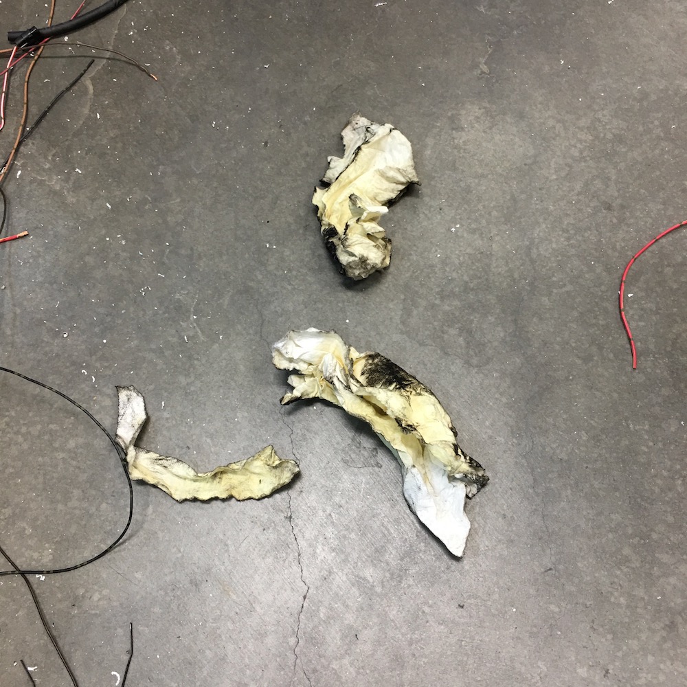
AHA!!!! You IDIOT! There were towels in the exhaust ports. They've been there for the past four years and they've been stuffed fairly deeply in the ports. There's been no need to remove them, even whilst building the exhaust system. I'd had the pipes on and off so many times that I'd not paid any attention to them during the last time I assembled.
Yes, I have a history of leaving paper towels in things... Air intake boots in MX bikes (yeah, we've all done this at least once), in a shock a few years back, in exhaust ports. Paper towel plugs happen!
So being that there are only two towels on the ground, and not three, lead me to start looking down header tubes. Yup, there's number three, firmly stuffed into the header.
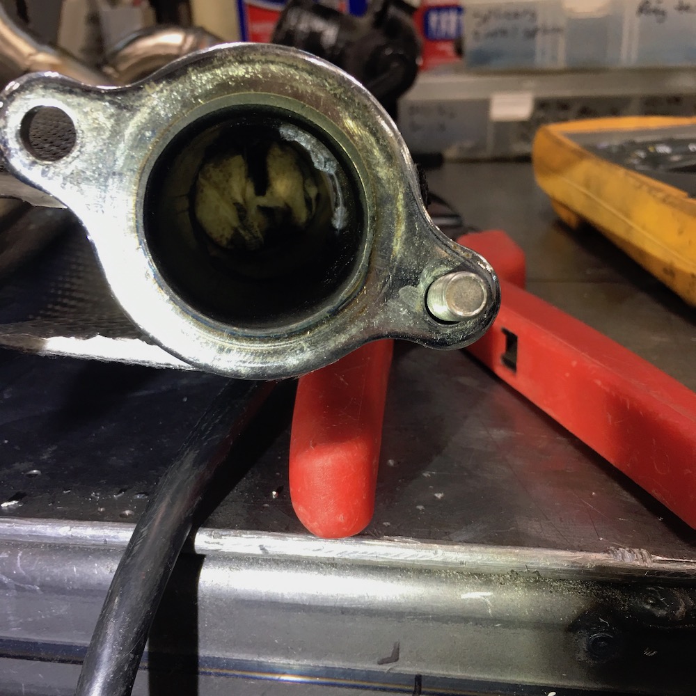
Outpatient surgery was performed (headers removed, towel removed), everything was reassembled and it was time to try again:
SHE RUNS!!!
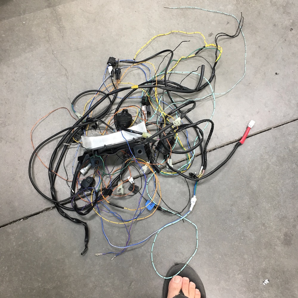
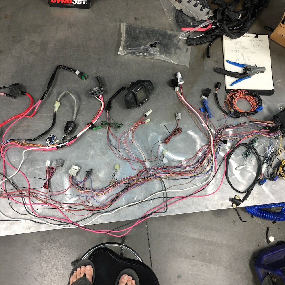
I've spent the past couple of days clipping, cleaning and tidying up the loom around the engine. It went from the pile of wires as seen above to yesterday's stopping point of this:
The pile in the middle is what was removed from the Nytro's wire harness. The pile of wire sitting back and to the right is an R1 harness that Glock sent me a while back for scavenging wire and connectors from and the pile in front of the Nytro's harness is what's left over from the three Phazer into Briggs installation.
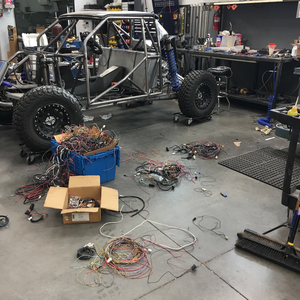
I'm waiting on OEM style connectors so I can finish it all up. While I wait on them I'll start working on the chassis' wire harnesses. The rear bumper, with the tail lights and license plate will have one large plug (makes it convenient to remove) and the hood's going to have a fairly complicated wire harness that controls the lighting that will also have one plug for convenience.
Things are moving along nicely.
Jul 7, 2020
Ever work on a vehicle and think "If I just had a tube to run wires through, that would make life so much easier."? Well, I have and now I have a tube to run wires through.
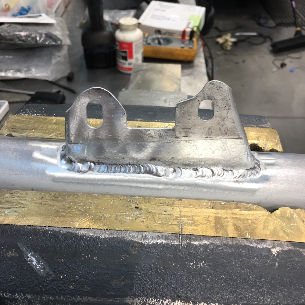
What was one of the best brackets I'd made thus far - too bad it was too short. So I had to make another, better one.
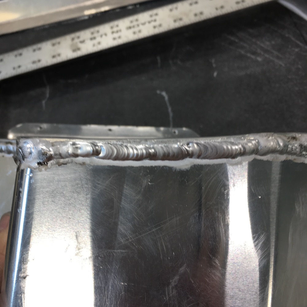
Discovered that there's a bad spot in my welding (and grinding off of the horrid bird shit weld I'd done.) Crap.
New bracket that fits perfectly and has one of the nicest aluminum beads I've manage to lay down.
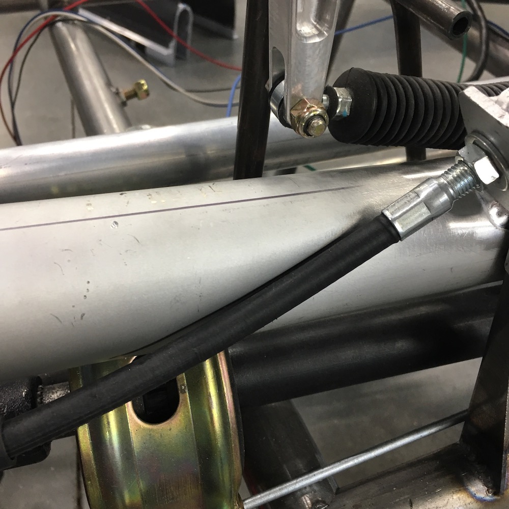
Finished tube in place. Flared the ends so there's no chaffing.
Amazing what one can do with a piece of 1.5" tubing and a bunch of beating the crap outta the aluminum tubing with it.
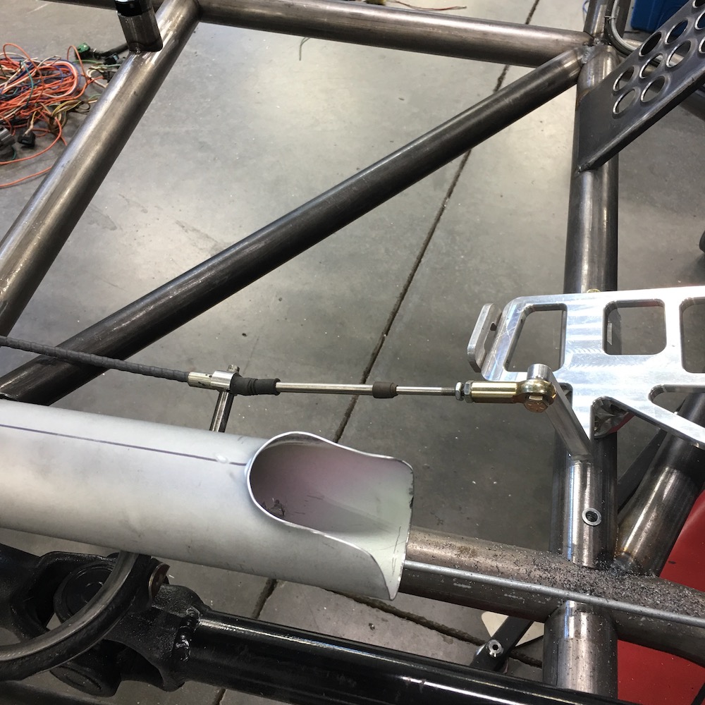
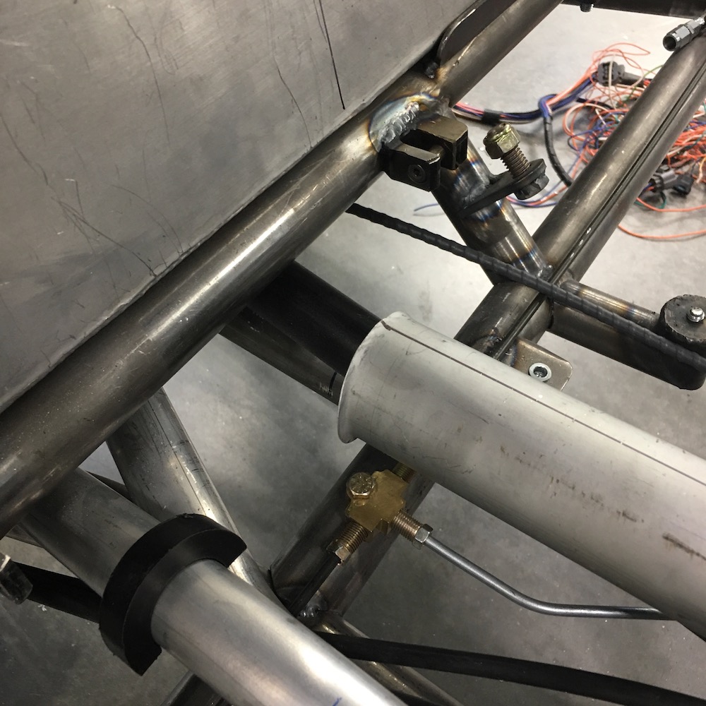
Even had to clearance the parking brake cable.
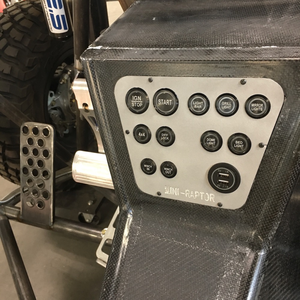
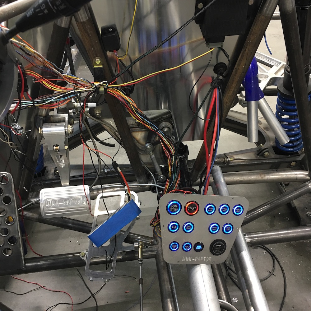
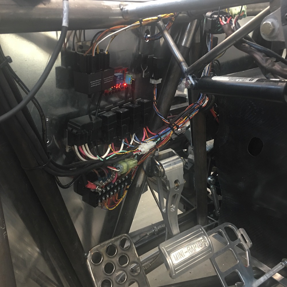
Billet Buttons getting wired in.
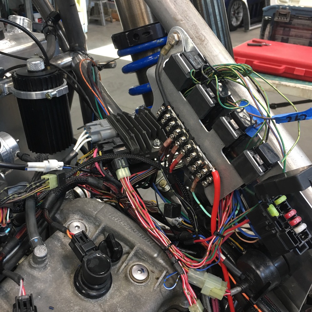
Finished engine side of the harness along with a power supply/ground strip. Still need to wrap everything but that happens last, once the entire harness is done.
Rear bumper/tail section comes down to this - six wires. Nice, neat, simple. And now I realize that I'll have to add another, at least, four wires... More to come on that this week.

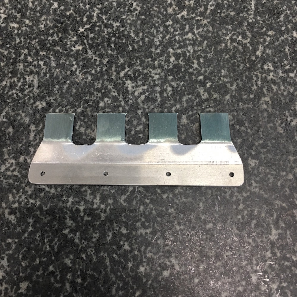
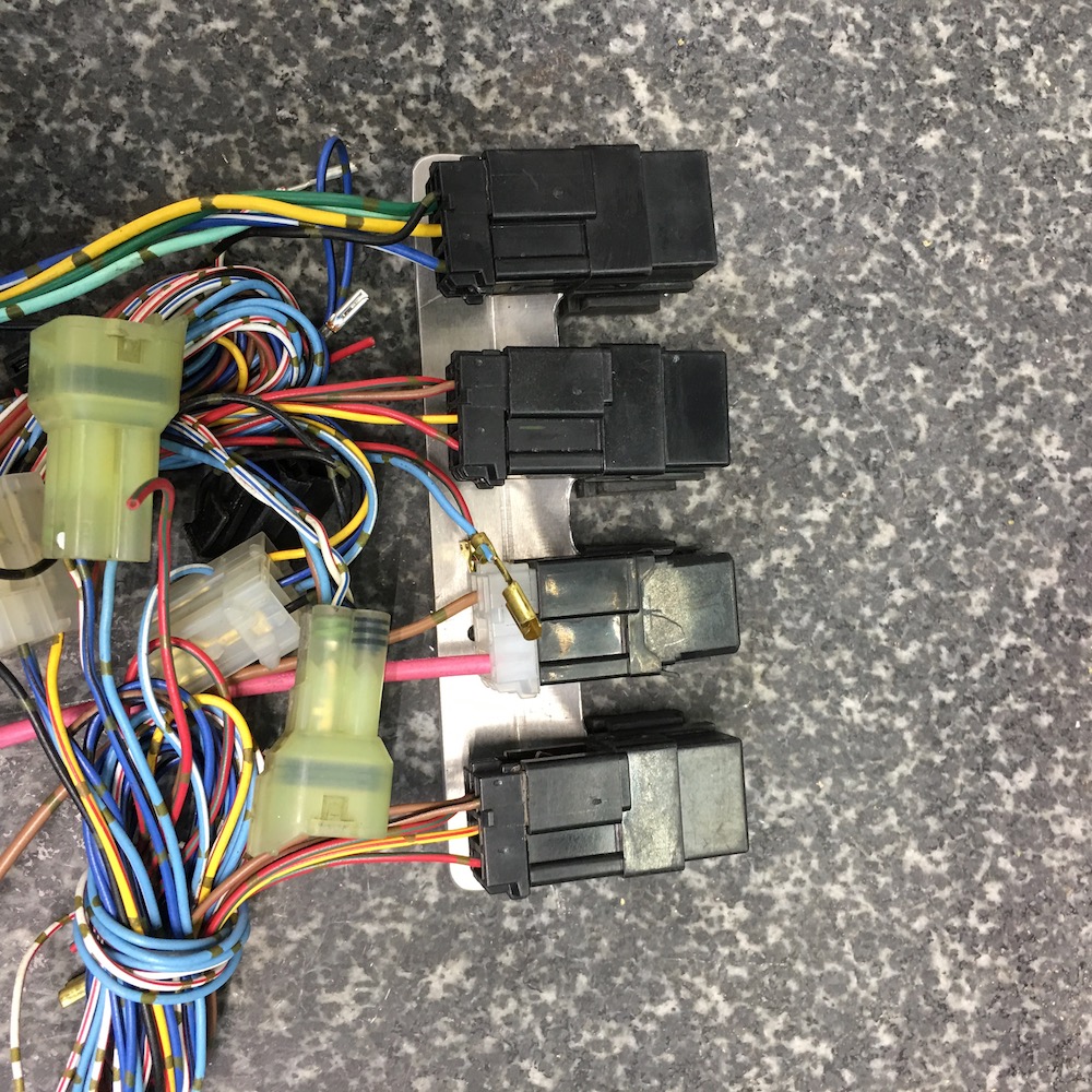
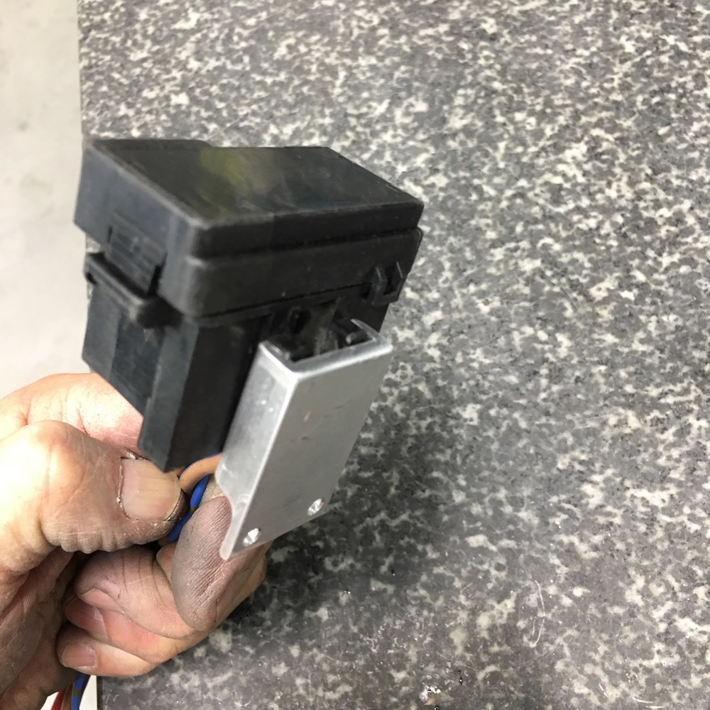
Keeping in theme of OEM Yamaha harness, made a relay mounting panel:
And a fuse box holder:

Stuff mounted on the front firewall:
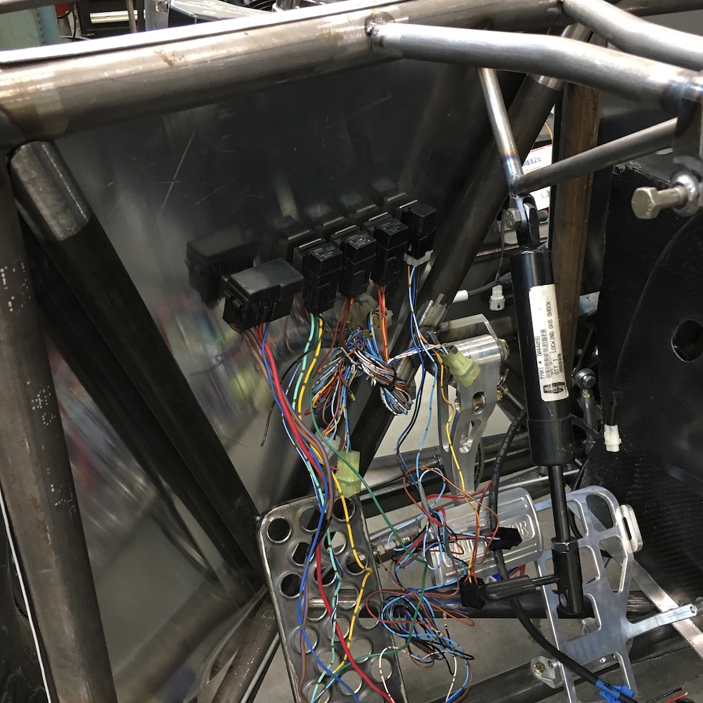
Believe it or not, I actually know what's going on here - and it gets a lot more added.
Running lights:
More wires:

Local friend who wasn't invited to help:
Oooohhhh Pretty lights!
Reverse lights:
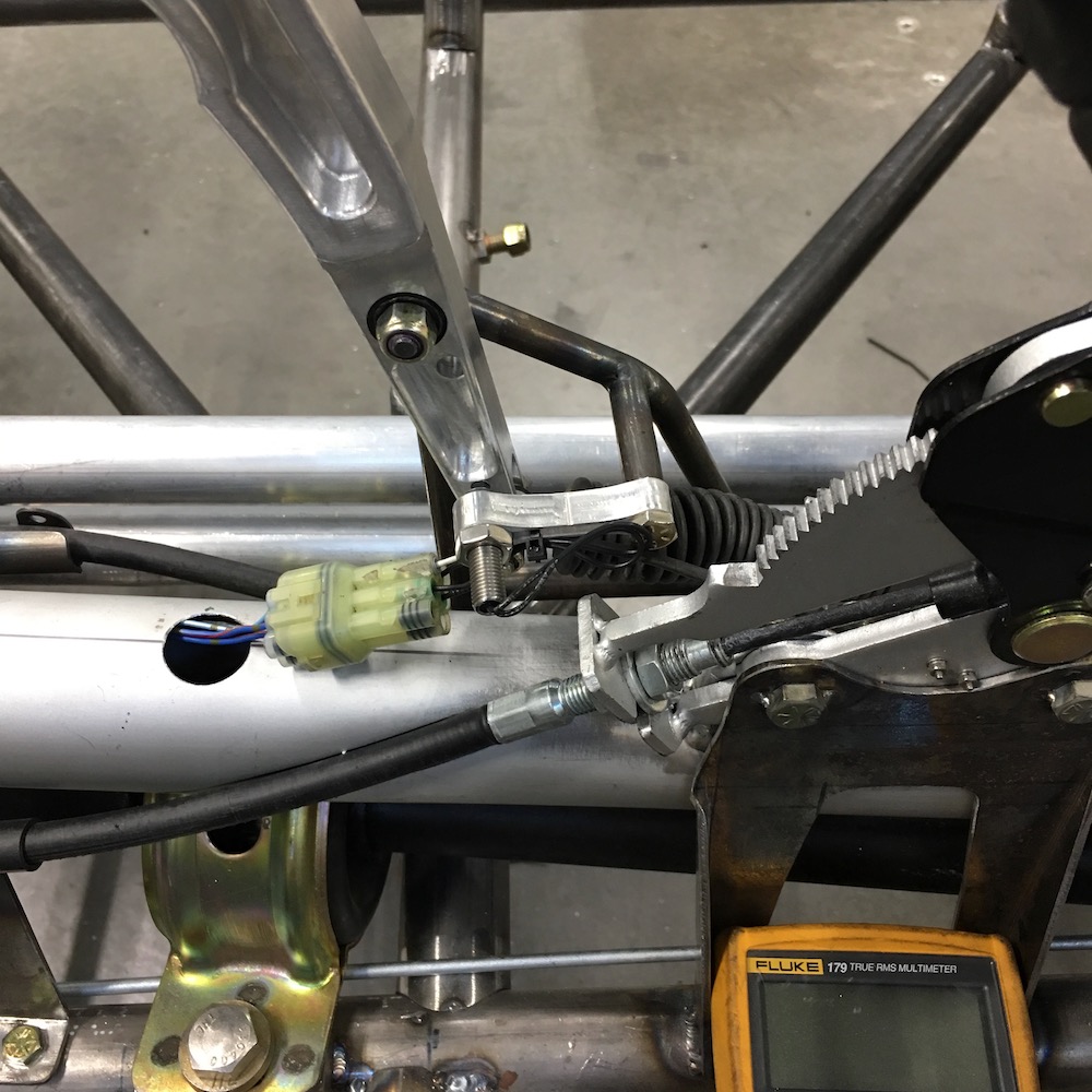
Parking brake indicator:
Reverse and parking brake indicator switches/harness:
Jul 8, 2020
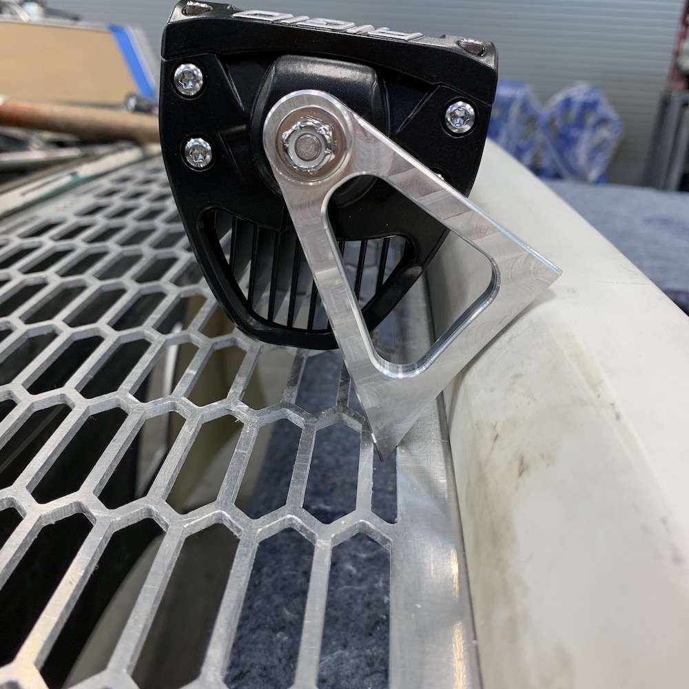
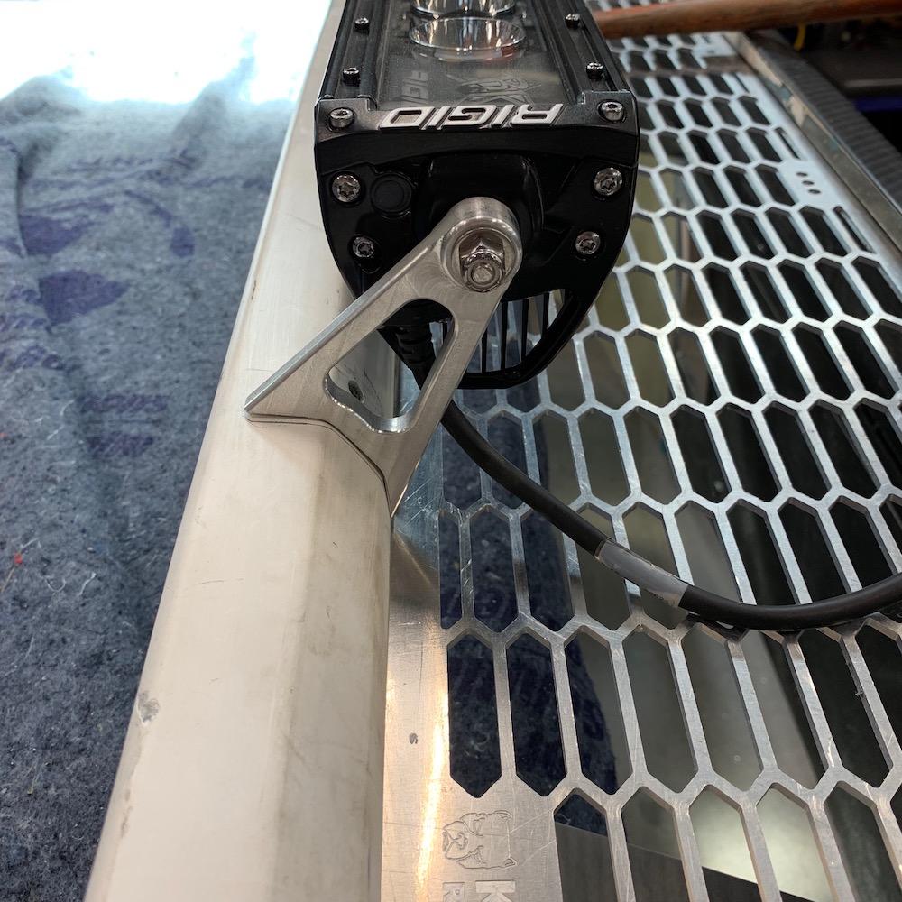
Night Vision is installed.
Baja Designs OnX that I got on sale a few years back when they introduced the next generation of lighting. It's 44" of bad ass, even if it is four years old. (:
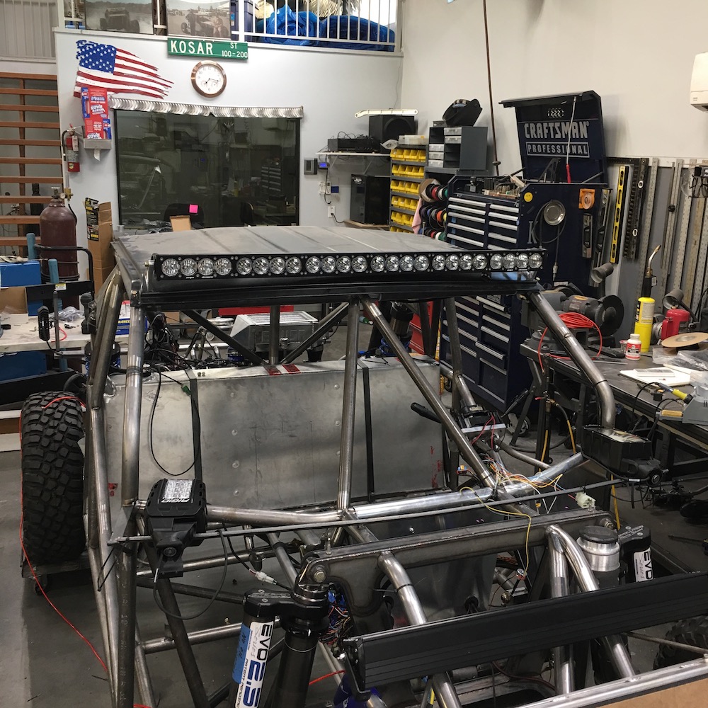
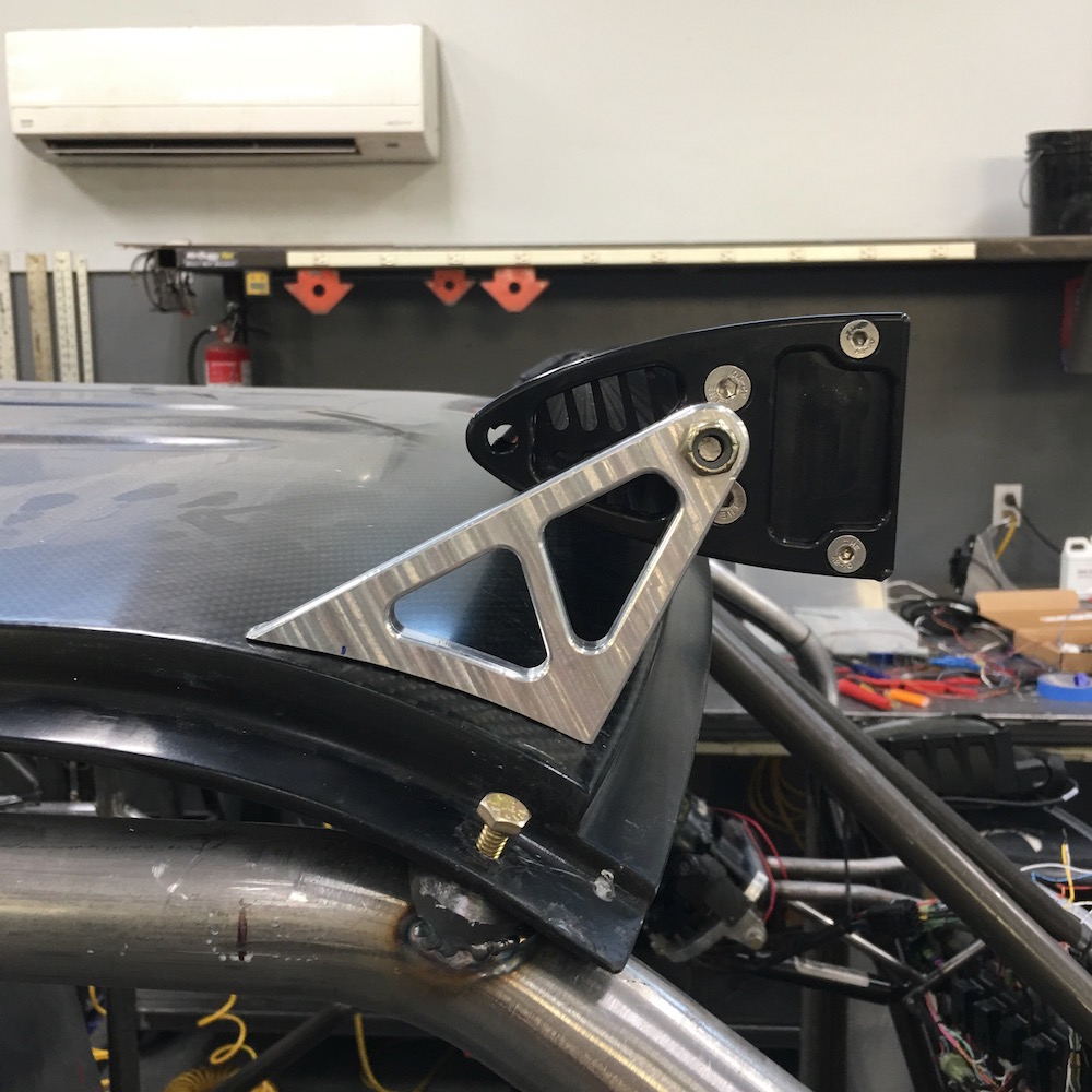
As usual, I had to do it twice. I needed at least three more hands today so my first, so thought generous clearance given, mount was about a half inch short. I had issues holding the bar in the correct place and taking measurements of any value. Best measurements ended up being from the first set of mounts - they showed me that I needed just "that much more" and they'd have been good. So I made a set with just that much more and then added the triangulation (swoop, style, billet!) for grins.
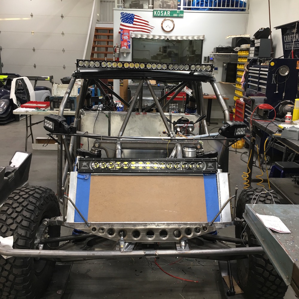
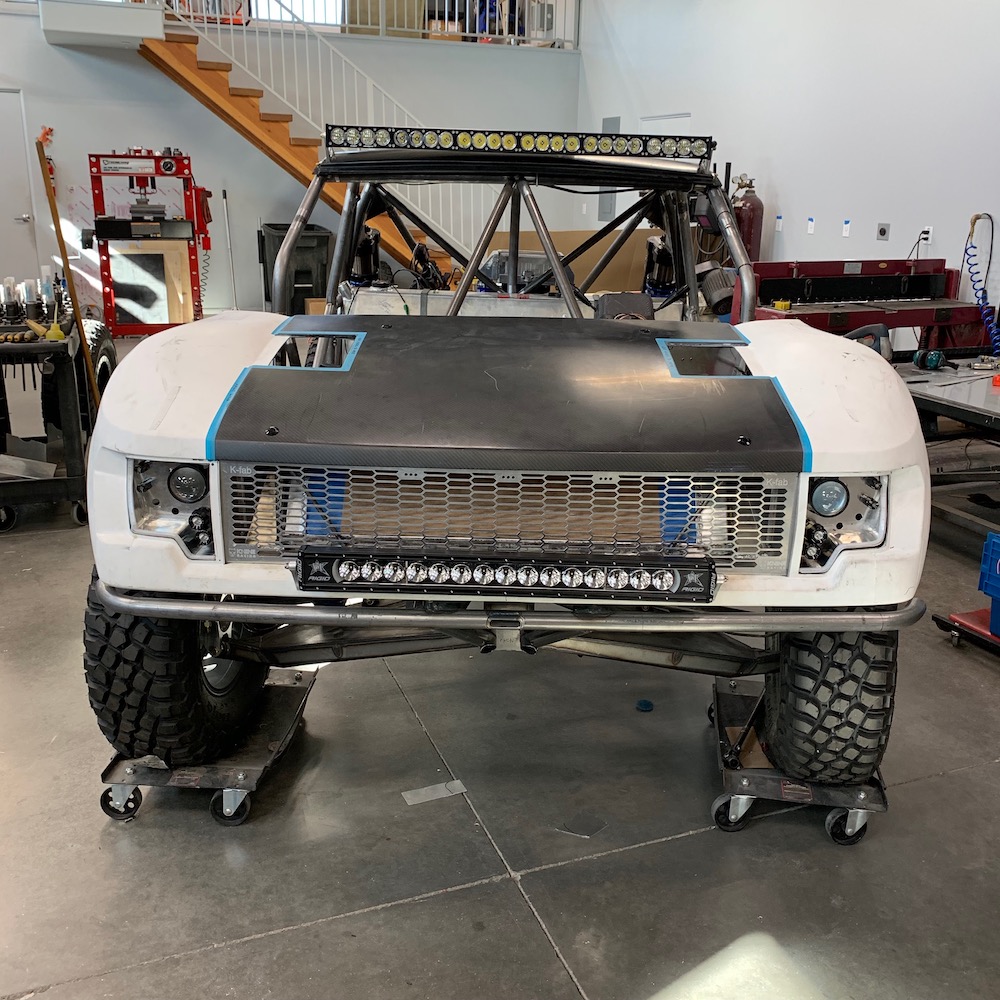
So with the BajaDesigns bar on top, the Rigid Racing bar on the grill (it's just sitting on top of the radiator, doesn't live there) and the Rigid mirror lights (great side lighting) I should be covered for just about anywhere including the dunes.
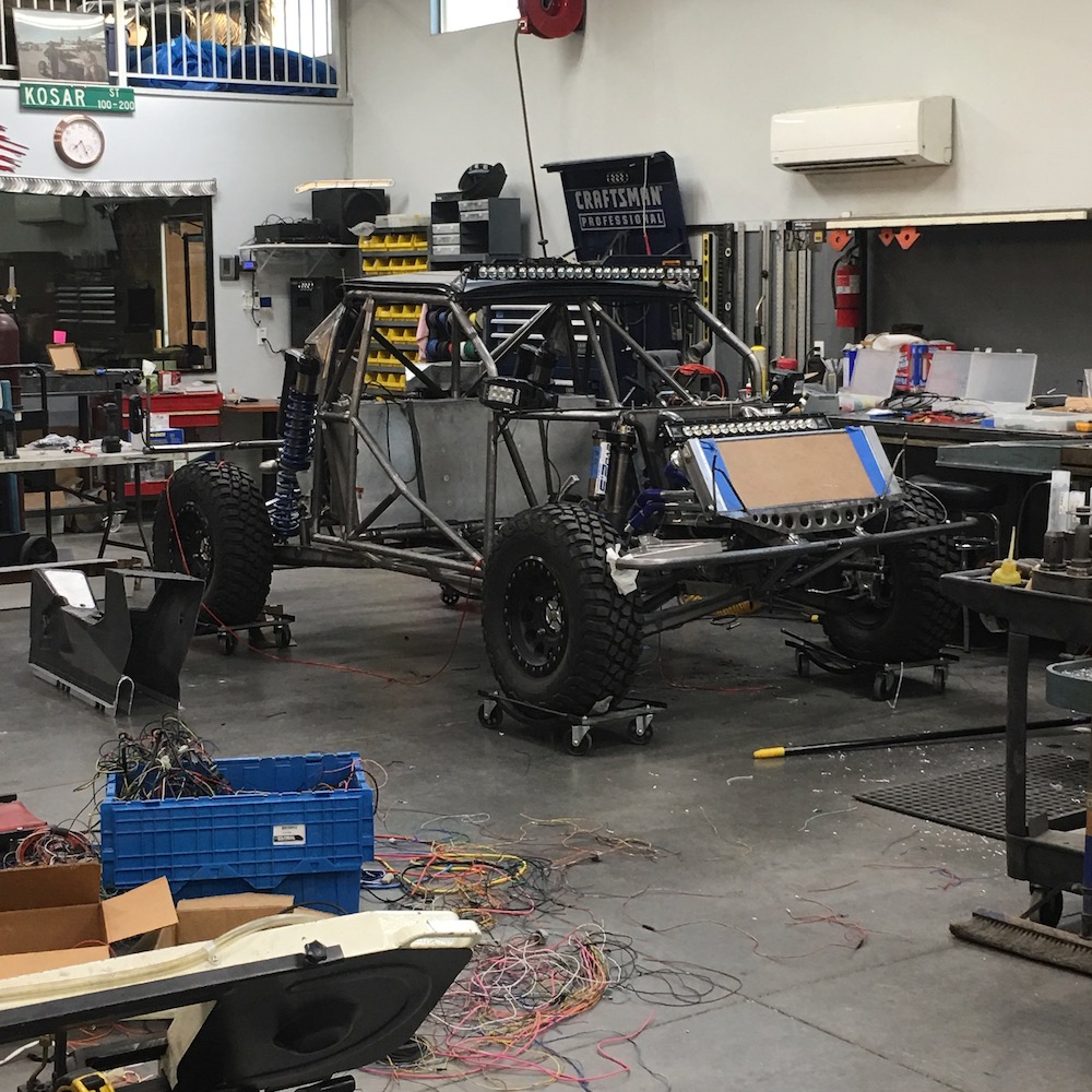
It looks like it's ready to pounce.
More wiring tomorrow. Getting closer.
Jul 15, 2020
Main wire loom is done(ish) for now and I've moved on to installing the lighting and wire harness in the hood.
I still have a couple sets of wires that need to run down the insides of the rear fenders that will control the running/signal lights among other things. Gotta get the radio and GPS gear wired in also - will happen when the dash rises from the drawing board, as will all the sensor lines and crap that go with the AiM dash.
Amazing what you can find for cheap on Amazon; the little circuit above the relays (]) flashes the high mount brake light for (a programmable) .8 seconds and then the light goes into brake light mode. Been seeing this on newer vehicles and like it. Anything I can do to keep people from hitting me I'm all about.
The two flasher boxes are for LED circuits and are also time adjustable. Made it easy to sync with the strobe timing in the rear lights.
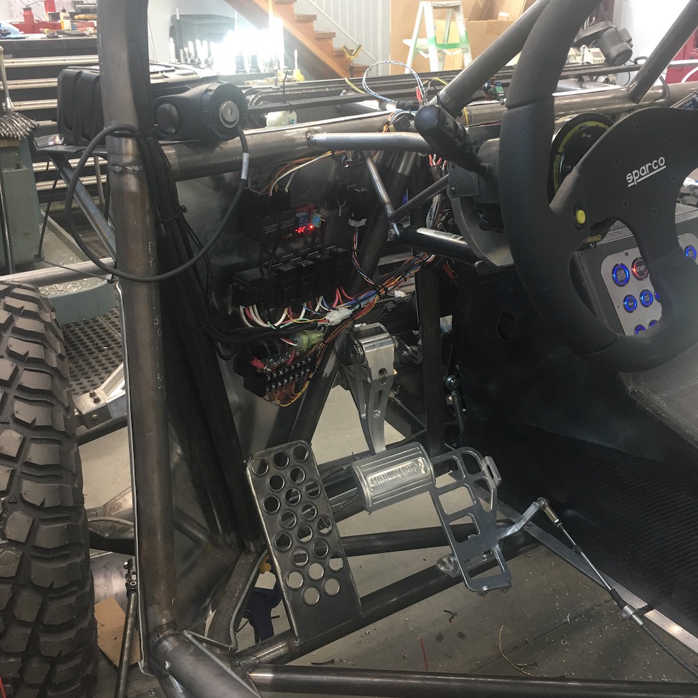
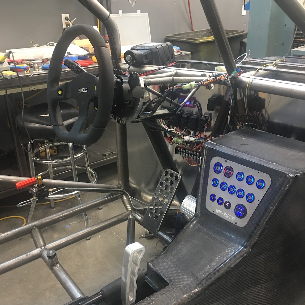
Center console back in place with the button panel installed. I like!
Glad I can dim these things. Once again, cheap Amazon product: 12v PCM dimmer
Teaser - she starts. Fuel pressure is really low so it starves out after starting. Just one of the MANY things I'll have to adjust.
Guess I shouldn't have been trying to steady my arm against the center console when it started.
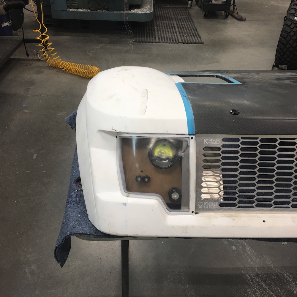
Starting to screw around with headlight placement. There's some grill trimming needed here.
And the next great Amazon purchase: Dual color sequenced amber running/signal lights
note to self: turn the phone sideways you idiot... You know better!
Prototype aluminum box to hold the headlights.
Now that I have the back and top section figured out I'll bend a piece to follow the contour of the outer and bottom edges of the cut out and then weld it to the flat back/top piece.
There's a lot of open area around/behind the lights that I'm not too excited about - but I have an idea that might make it more interesting - gotta make a press mold and see if what I see in my mind will transfer.
Another idea is to anodize the background and then run some RGB LED lighting in the top so it backlights. Dunno - all sorts of options/ideas/thoughts floating through my pea brain. Who knows, maybe even accent with a bit of carbon, like the Wizard mentioned. It definitely won't stay aluminum in color.

Jul 16, 2020
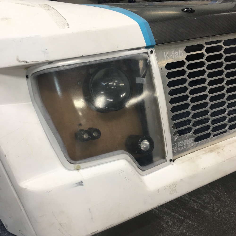
Prototype and the box that the prototype lead to:
Fits like a glove!
There's a small gap that will get massaged away - or I may end up putting the marker lighting between the aluminum box and the opening for the lights. I'll figure it out today.
And suddenly it clicked. Ever work on learning something and all of a sudden it all comes together and clicks?
Right here on the side of the box is that moment. I can TIG aluminum!
Now I just have to start working on consistency - which will come with all the TIG welding I have in my future.
Been a good Critter of The Day day.
Got all excited this morning as I raised the shades. There's a medium small blonde tarantula on the porch! WOO HOO!!!
I go outside to check it out and darned it, someone's taken its front left leg and it's life had leaked out.
It'll still make a nice addition to my collection of creepy crawlies. Kinda ironic the piece of paper I found to put it on, eh?

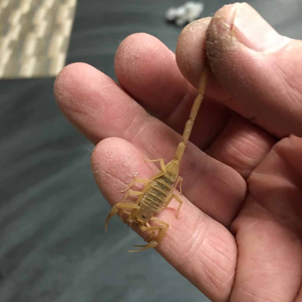
And, because it's so very dry right now, the spiders and scorpions come into the house seeking water. Robyn had a scorpion in her bath towel yesterday morning (you'd think after being stung once and having a very bad day she'd shake the towel religiously - I sure do. Shoes too...) and this guy, a fairly large Arizona Bark Scorpion (the bad dude), was under the recycle bin.
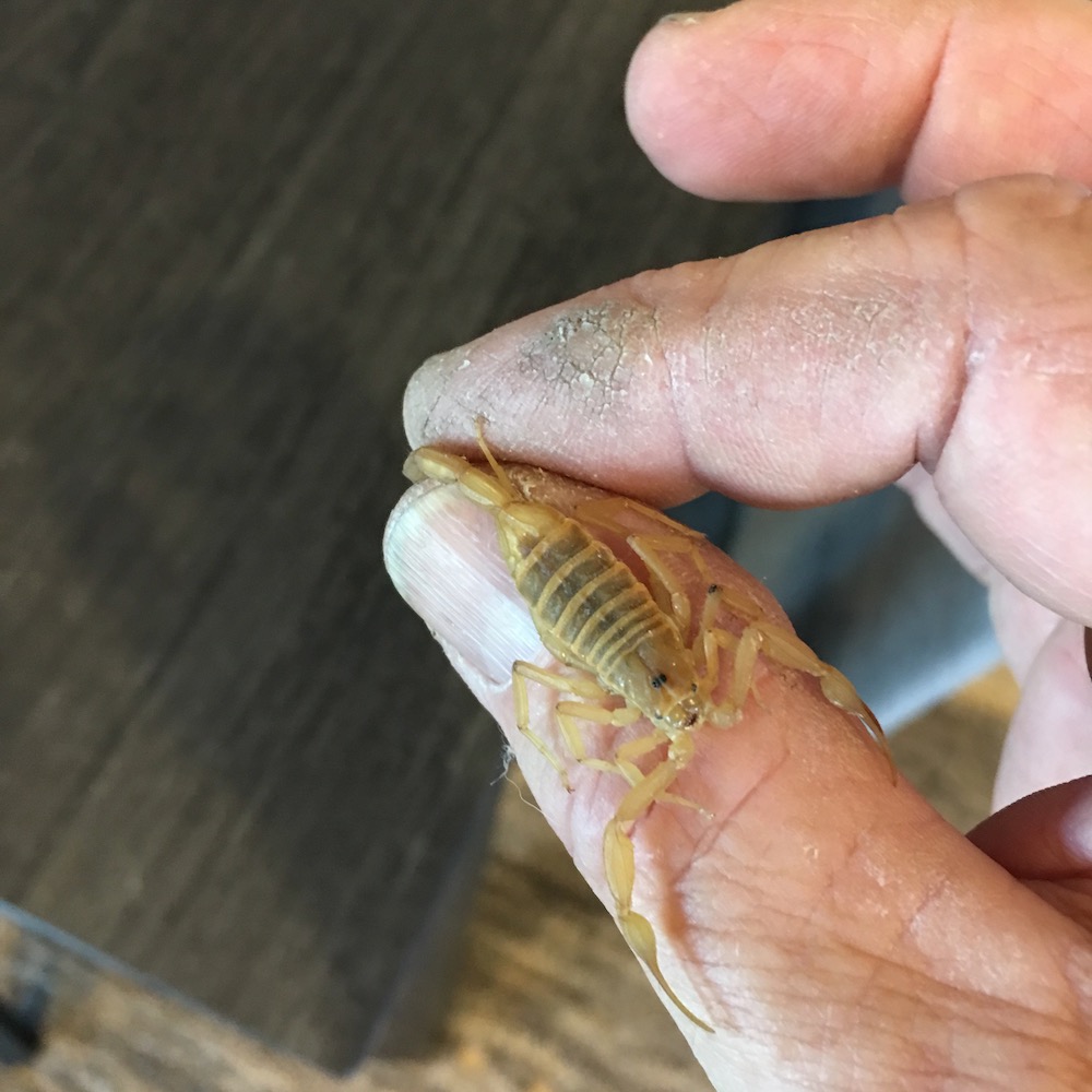
Usually they just go limp and hang by their tail. This one was not happy and put up a fight. I'm impressed with the strength it showed trying to pull its tail loose. It also was aggressive with the pincers and was grabbing and pinching where ever it could - I think both for traction and to see if it could cause any damage. It's not enough to hurt even a tiny bit but you can definitely feel it grab and bear down.
Power to weight we'd not stand a chance against one of these things. We're soft, weak and squishy comparatively.
Jul 29, 2020
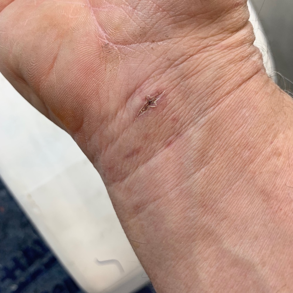
Been down since July 19th. Had carpal tunnel surgery on my right hand so I've had to take it easy and not play. Planned this for a while - it's hot and not riding season here presently.
They went through my wrist this time. When I had my left hand done about seven years ago they went through my palm and it was tender for a long time. This is already better.
So besides being BORED and watching a lot of TV I've been at the computer playing around and designing/drawing stuff.
My original roof light bar mounts ended up being the correct height for the grill bar but they weren't the correct shape:
Yesterday I was finally able to get back in the shop and play. Knocked out better fitting mounts:
I've also been playing with the 3D printer again. Originally (waaaay back in this thread) I did eight louvers that were round - kind of classic shape, if you will. Decided I didn't like that so I knocked out a couple testers that will be four louvers across the hole.
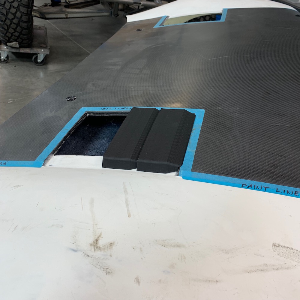
Got pretty close - need to widen them a bit and blend into the corner where the white fender and carbon hood meet.
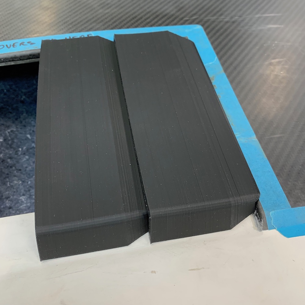
Anyone wanna take a guess? This is the top side of them. Making 100 of them.
Jul 31, 2020
Almost done. Still have to finish later today:

Aug 9, 2020
Left side headlight cut out.
Took all of fifteen minutes to do this, including the fine detail/blending/shaping work which you don't see in this pic. Wish everything went this easily and quickly.
Fitting of the second back plate (cut first one too small - not enough edge room to work with) on the third framing strip. This stuff is a pain in the arse - especially trying to mirror the other side (hence the three frame pieces).
Since the headlight boxes bolt in and use part of the radiator shrouds I had to make billet pieces for the 2.5mm bolts to thread into. The .065 aluminum sheeting just doesn't have enough surface area to not end up stripping out.
Headlight box welded up and in place. That thin stuff is tricky - I'm getting better but I'm not gonna show any close ups.
Still massaging to get it all fit. The front hasn't been trimmed yet in this pic.
I'm not really sure how much I need to seal up the headlights (probably best I can - gonna get silicone messy, oh the joy) so I knocked out a couple fillets that blend the grill to the hood. You can see the billet mounting bar (shown above) behind the grill.
Hood harness happening:
Hood in place. Honestly, I'm not sure how much I like the headlight layout yet. Fortunately it's an easy thing to mess with. I can make an insert that covers the entire back of the box with a different pattern/placement of the components. I noticed a couple of days ago on the full sized Raptor that the main headlights are outwardly placed and more in the nook on the side. Dunno... something to think about.
The back of the boxes still need attention. I'm thinking either some sort of ornate billet piece or maybe an insert that has accent holes - have the plate one color and the accent holes will let the, what will be flat black, back show through. This is one of those "happens later down the line" things when I get closer to finishing and am doing attention to detail shit.
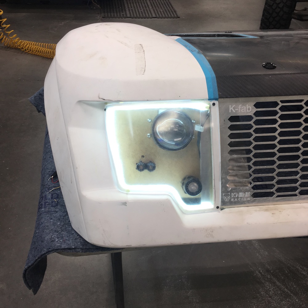
Lighting in action. Still waiting on five of the little Morimoto light pods (didn't order enough originally, then ended up getting four that were wrong and I screwed one up).
Now that the hood is, for the most part, finished it's time to head back into the cab and start working on the dash.
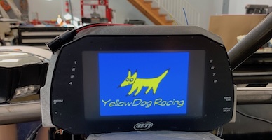
AiM MXG 1.2 Strada dash/data logger firing up.
The stuff this thing is capable of is incredible. It'll monitor just about anything you can think of that's automotive related; voltage, temps, pressures, exhaust gas AFR, infrared temp (using this on the clutches & belt) suspension and steering movement just to name a few. I don't have any sensors for motion of anything, though.
Wanna measure and store something? AiM has a component that will do it and report back to this dash. It'll also control things like cooling fans and information lights (low fuel, high beams).
It's fully programmable and you can add as many pages as needed to convey all the info it's reading.


Aug 11, 2020
Bitching session time...
While the Morimoto lights are pretty cool, the instructions and documentation that (doesn’t) come with them SUCKS! They have everything, yet nothing useful, on a website that’s more into being flashy that helpful. Your web site SUCKS, Morimoto.
The little motopod minis have wires that are exceptionally delicate - like two of them pulled out of the component delicate just stripping the wire (and yes, I have proper tools and know how to do it - been screwing with electronics for 45+yrs).
The headlights give you absolutely NO indication of top/bottom orientation other than an M cut into a plate behind the lens. One would figure that the M, for Morimoto (or in this case Moron) would be oriented so it’s an M, not a W. WRONG! I’ve discovered that even after trying to be careful and get them installed correctly they are upside down. Just an arrow or “this side up” would be helpful.
Had them shining on the wall, showing off my work to me better half and noticed when I activated the high beams (opens a shutter) the bottom of the projected lighting would show more. No, no, no... It’s the top of the projected light that’s supposed to open up. Shit.
That redo of the back plate may happen sooner than I was planning.
Busy right now trying to get all the AiM components installed. All the pressure and temp sensors are in place and I’ll work on running harness wires and such for them next. Gotta figure out the lengths of the connection cables and get them on order.
Aug 16, 2020
Requested pics. There's 200 lbs of crap shoved into a 50 lb capable space in this thing. Not exactly sure what pics were wanted, not easy to get any shots that really show much either - especially concerning layout.

Aug 21, 2020
Had to step away from the front end (lights) and move my focus to something else. Part of the beauty of this project is when I get frustrated or tired of one aspect there's a bunch of other things to tackle.
Quick side story (that many of us can relate to): Purchased a set of 430cc injectors last year on the advise of two sled performance shops (Ulmer Racing and MPI, who makes the supercharger setup) since I'm closer to sea level and have different temps than sleds play in. Got them when I got all the DynoJet stuff - auto tune, tuning box, etc..
The injectors have been sitting on the bench in the corner and a couple of months or so ago (when I started getting into the wiring) I decided they were in a place that was dirty and not the best. So I stuck them into one of the DynoJet boxes and put it....
Yeah, I'd like to know where I put it.
I have a very bad feeling that it got tossed with a bunch of other small black boxes. I have two of them left, three gone and injectors nowhere to be found. For the past two weeks I've searched with no luck. There's a Snap-On 1/4" drive floppy wrench missing also - maybe they hooked up and ran off, dunno.
Yesterday I call Ulmer Racing. "Hi, my name's Richard and I have a problem." Told the guy what was up and he says "Yes, here you go, you got them last October." He laughed at a couple of his own "I'll put this in a safe place" experiences and said that when/if I find the missing set, just send them back and he'll fully refund me. Says it's a common piece and they sell them all the time. Man I hope they show up!
-------
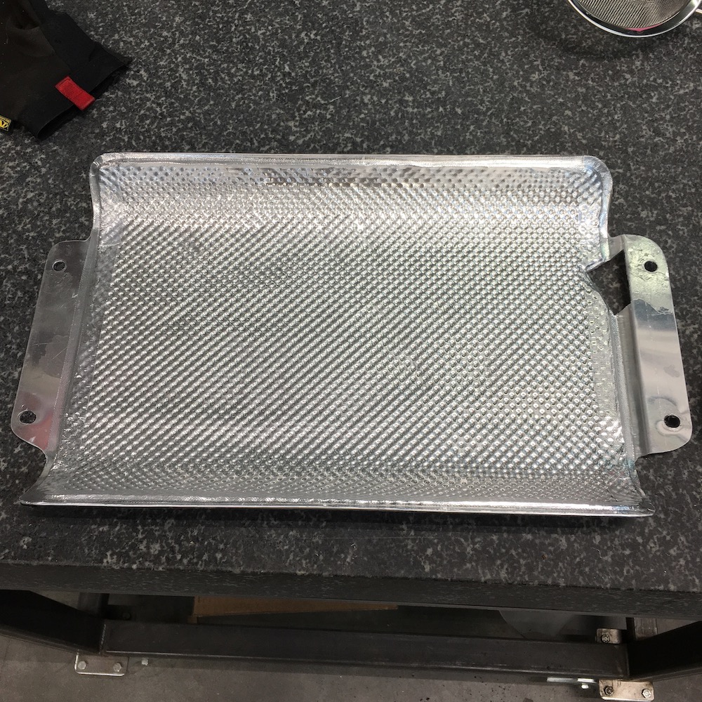
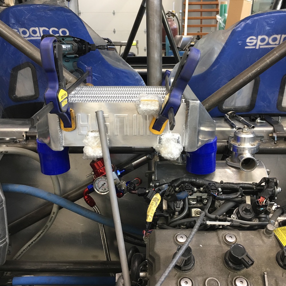
I had to strip the induction system off to do a bit of sensor installation.
While the intercooler was off I went ahead and made a, flat this time around, new screen to keep things from damaging the fins. Even with the first test screen taped to the cooler the fins got dinged. Too darned tender...

Intake plenum.
Left to right: Boost pressure, boost temp and atmospheric temp, which may get moved. I'm afraid it's going to read the heat soaking that will happen on the plenum.
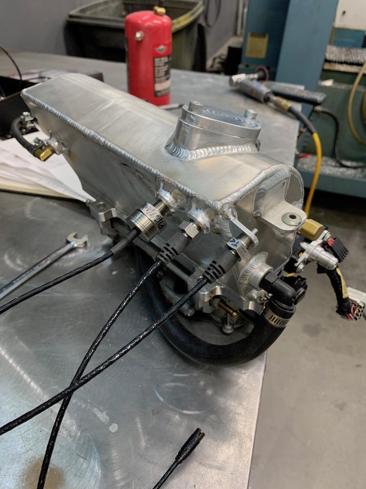
Whole bunch of stuff going on here. The manifold has the water/oil heat exchanger line (black hose), the main water line out (blue hose on bottom) the OEM temperature sensor and the AiM temp sensor.
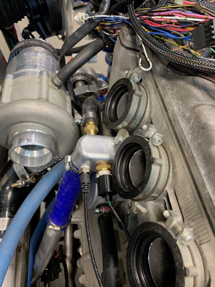
Oil temp sensor. Have been informed by the Wizard that I should be measuring the temp going into the engine (bottom of the sump res) instead of what's coming out (where I put it). I really wonder how much the temp changes between the top and bottom of the system once everything's up to operating temp.
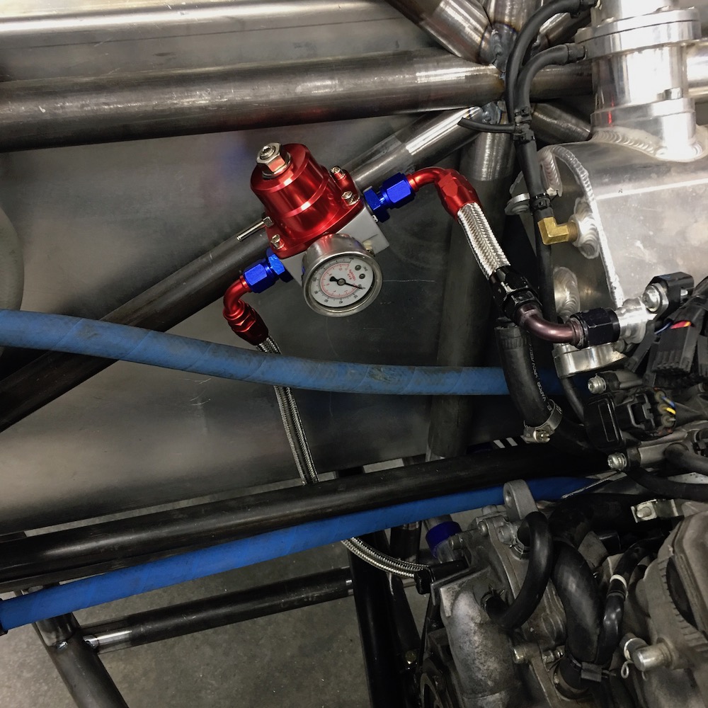
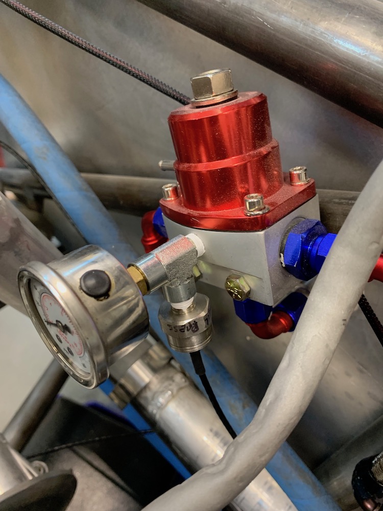
Fuel pressure sensor - and once again I've been informed that I need to put a hose off the exposed barb and run it to the manifold to make regulation better. Fortunately there's a bung in the perfect spot on the plenum box that just needs to be plumbed to. 5 minute job (and now that I've said that it'll become an hour).
The AiM system is extremely expandable. There's a data port with four channels. You can plug in another data port and now you have seven (one is used) and you can keep adding to your heart's content. Each data port can take four channel expansions so one data port can talk to up to sixteen components.
I'm reading twelve "live" channels with the AiM system.
Speed sensor - going to put on rear and also have GPS so I can see how much wheel spin I have.
Oil, plenum (boost) and fuel pressures (have a brake pressure sensor that may get stuck in for grins if there's a spare channel)Oil, water, plenum (boost) and atmospheric temperatures
Lambda for air/fuel ratio:
Three infrared sensors for CVT system temps.
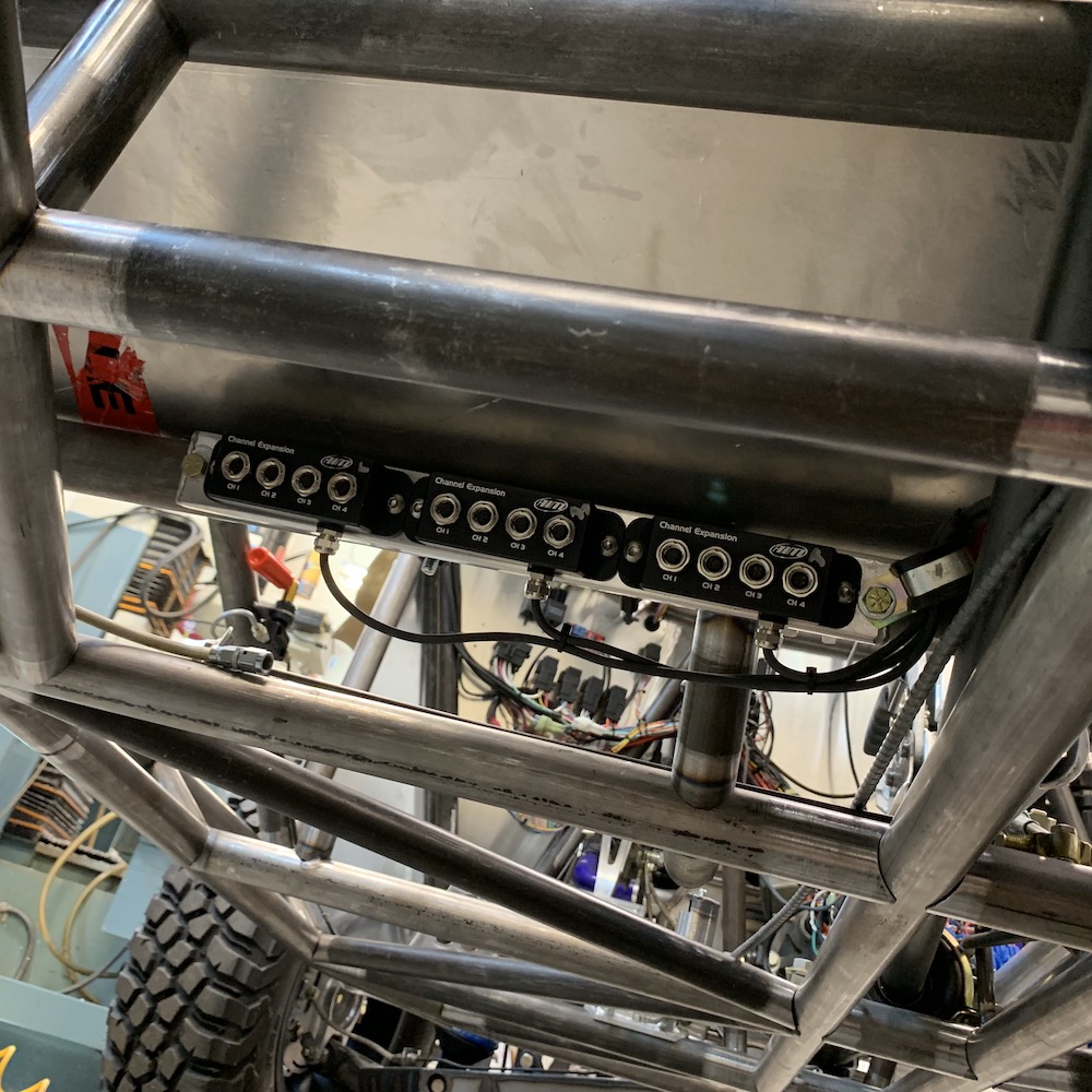
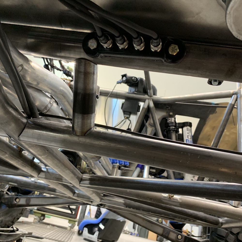
These are the channel expansions:
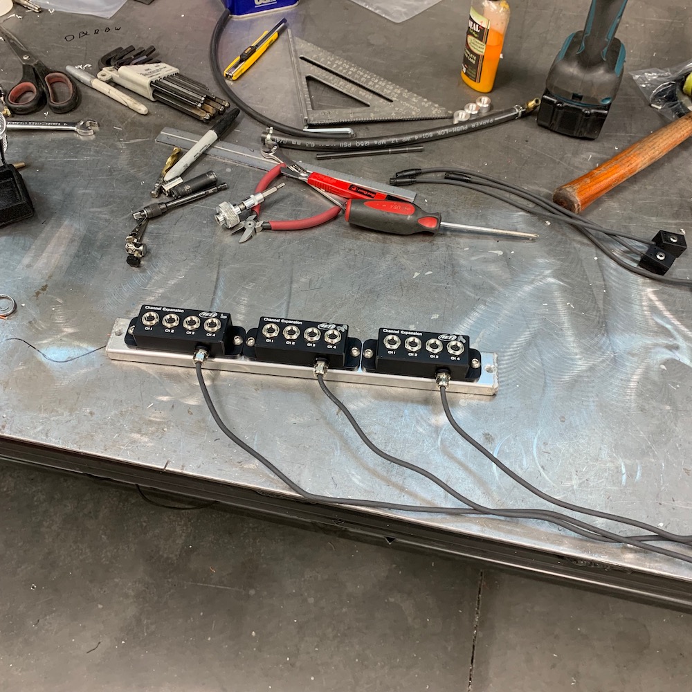
Tucked nicely up under the fuel tank in an area that will be fairly well sealed from the outside world. The stuff's all waterproof anyhow.
The three channel expansions and the Lambda sensor report back here to this hub:
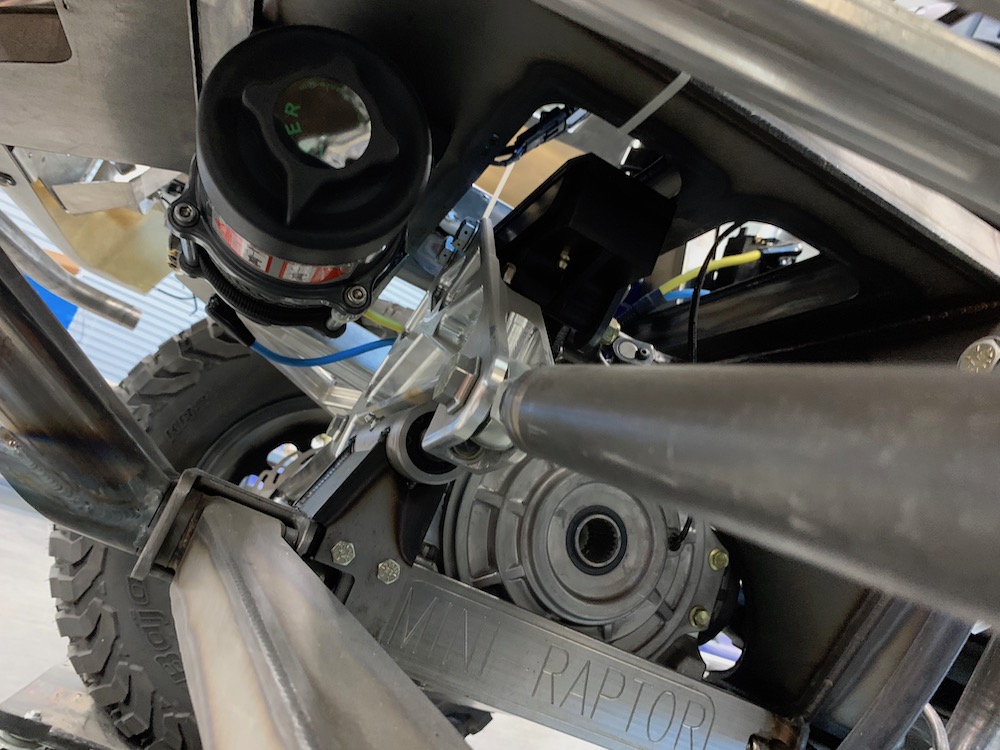
This little gem is the CVT temperature monitoring system. I've taken a set of infrared tire temperature sensors and pointed them at the CVT components. Each sensor has a 35 degree field of vision.
This is a preliminary/test setup - already thinking that I need to point them more directly at the components they'll measure.
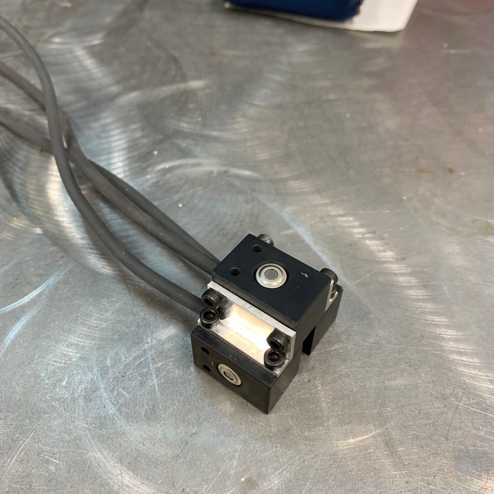
It's going to get placed here in the middle of the CVT drive train. It's probably the safest place, as when the belts let go they tend to go away, not inward. That said, if I have one fray it can get caught up and whip the shit out of anything around it.
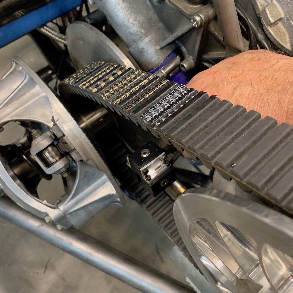
I'm already thinking that the way they're pointing isn't going to do a lot as far as giving me quality temp info. I need to point the two horizontal sensors at the stationary sides of the clutches and getting a belt temp reading from the inside is sort of a moot measurement - really need to get the side of the belt on the contact surface.
With the 35 degree field of vision, if I put the belt sensor half way between the clutches and in line with the belt, say up against the engine, pointing outward, I could read the side of the belt fairly accurately. The distance between the top and bottom of the belt doesn't change much as the clutches do their thing.
Being that I'm not going to enclose the CVT system, just make a scatter shield, I should have a few options on where to place the IR sensors. Other than the RZRs, none of my CVT drive trains have been enclosed. I'm not in a wet environment (Hell, we NEED RAIN!) and I never had problems because stuff was exposed to the elements. Maybe a bit more wear on some of the sliding pieces but nothing that makes it necessary to enclose in my eyes.
LOL - just got off the phone with my friend who makes guitars for the stars and was my tenant in my shop in Ohio.
He always gave me shit about the timeline on the Mini-Raptor. He called it "2020" saying that's the year it would be done.
As we were chatting about it's progress I had a light bulb go on regarding the license plate. I've been trying to figure out what to put on it - has to be a vanity plate. MINIRP, MINTOR, MINRAP. Nothing that worked, though. And then it hit me: MR2020 Works perfectly, is a great inside joke and will be what I hope is available when it comes time to get it plated.
Aug 23, 2019
4.5 hours from concept to finished product.
The IR sensors have a 35 degree field of view so I started seeing what they'd see and where to put them.
Front cutch is where I started:
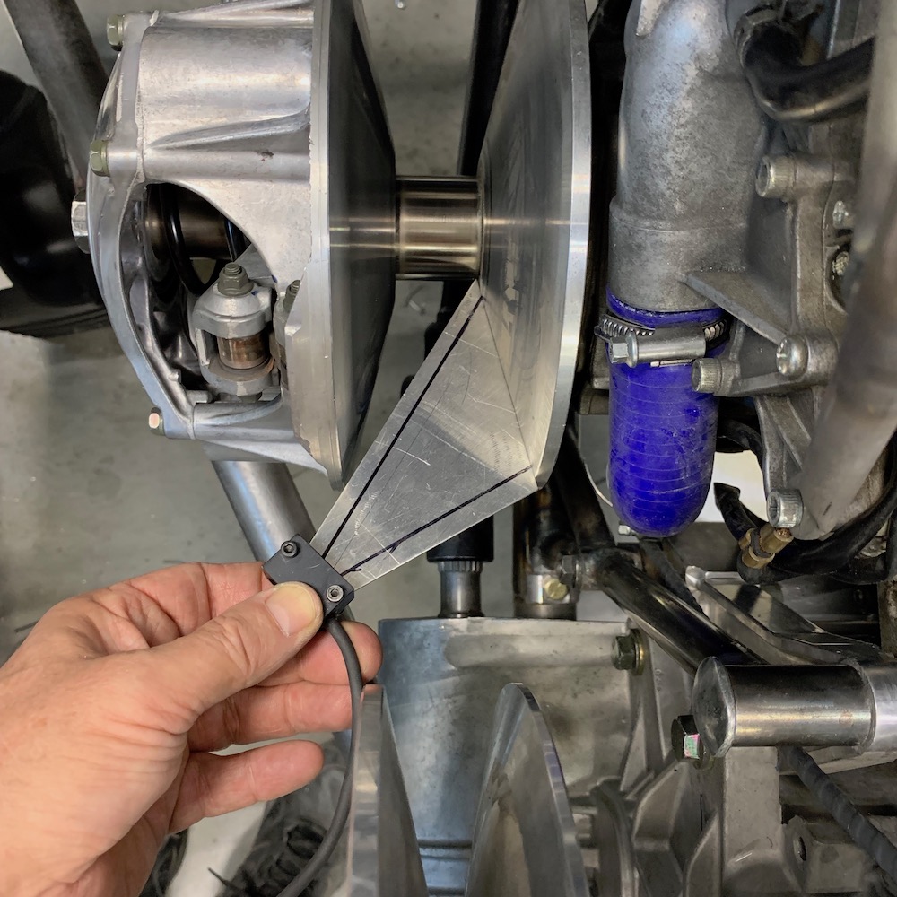
Then worked the back sensor in place:
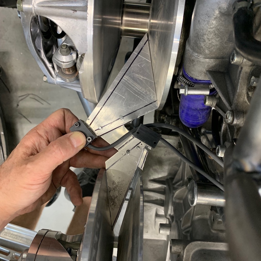
Once I got the field of vision dialed in I made a template arm:
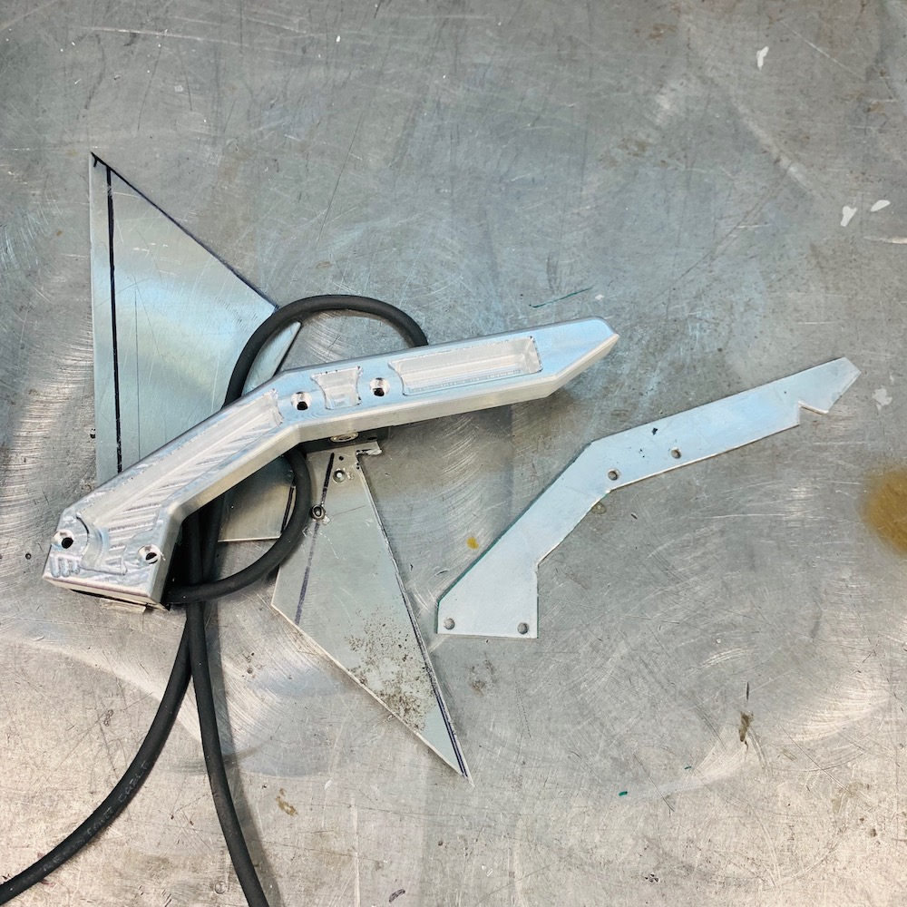
Ended up with this:
And it goes here:
Aug 26, 2019
All three CVT sensors mounted and ready to play:
Used the field of view template to figure out where the belt temp reader needed to sit - worked out perfectly to mount it on the intercooler support.
Still wonder what happens when a belt decides it doesn't wanna be part of the system anymore. Hopefully I'll not find out...
Sep 6, 2019
AiM system in and running.
Another box checked.
I'll finish the hood harness next and wiring is done! (except for rear turn signal strips)
Finding all leaks in the cooling system next - will use air, as my dumb ass used oil to find all those leaks and I iz smarter now.
Just one of a bunch of cables I got to shorten while getting the AiM system wired and hooked up. Of course my first round of soldering was backwards so I got to do them twice - it wouldn't be part of this project if I didn't do some aspect of each step twice...

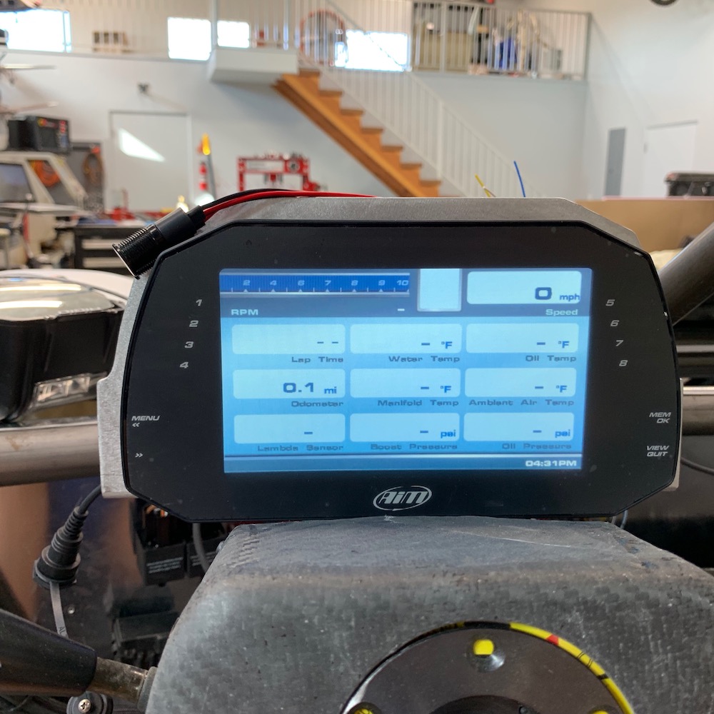
Dash in action:
Lights 1 and 2 will light up as temp indicators. 2 at 205F, 1 at 210F.
Light 3 is low oil temp indicator, hence it being on.
Lights 4 and 8 are set up as turn signals and there are arrows that pop up too (haven't figured out how to make them flash yet).
Lights 7, 6 and 5 will light up with boost pressure like a tach does rpm.
The tach lights go across the top and turn on in the power band range.
Run through the screens:
First is what I'd call "Car Mode". Has icons and layout like you'd see in a car. Oil low pressure is indicated until I hit start.
The temp next I thought was supposed to be dark until temps are high - need to check that.
I run thru some; 4x4, rear diff lock, signals.
Next screen is all the temps and three of of four pressures.
The big 1 is gear. Still have to figure this one out.
Third is another "Driver" display.
Missing the full sensor display (not sure why it didn't pop up. think I double bumped the view button)
Thank you Matt at Trailtech.net for the help!
Oct 8, 2019
Frame's been stripped down to the bare bones and is getting ready for welding. I went to Harbor Freight Sunday and picked up two 1000 lb. engine stands (they don't make the 750 anymore, crap) so I can make a welding rotisserie later today. After I help Robyn hit the grocery store I'm locking myself in my shop and working, damnit.
Let the strip show commence!
[IMG]http://yellowdogracing.com/Raptor/IMG_0254.jpeg"> [IMG]http://yellowdogracing.com/Raptor/IMG_0255.jpeg">All this crap (and more!) fits inside that cage.
[IMG]http://yellowdogracing.com/Raptor/IMG_0256.jpeg">Fifteen pounds of wire harness - it just barely comes out. Will be the second thing back in on reassembly - brake lines are the first.
[IMG]http://yellowdogracing.com/Raptor/IMG_0280.jpg">Out with the power plant.
[IMG]http://yellowdogracing.com/Raptor/IMG_0290.jpeg"> [IMG]http://yellowdogracing.com/Raptor/IMG_0310.jpeg">Seven bolts holds this whole thing in:
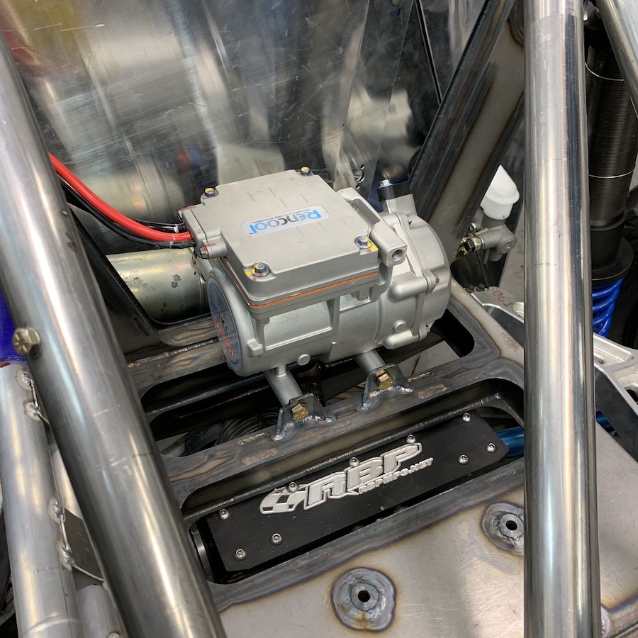
[IMG]http://yellowdogracing.com/Raptor/IMG_0309.jpeg">Was directed to a company in Australia that makes DC air conditioning systems for industrial equipment and now I have a 12V DC compressor! WOO HOO!!!! Pulls 15 to 68 amps depending on speed (three available)
[IMG]http://yellowdogracing.com/Raptor/IMG_0311.jpeg"> [IMG]http://yellowdogracing.com/Raptor/IMG_0312.jpeg">Bare frame, ready to be mounted up on the welding stand:
[IMG]http://yellowdogracing.com/Raptor/IMG_0313.jpeg">There will be work this week!!!!
Oct 9, 2019
Three steps forward, now just one back.
After all the work and crap, A little more time is no biggie. Back together raw, take out beat it up, pull apart, paint.
She's on the BBQ rack now - makes getting to everything SO much easier.
[IMG]http://yellowdogracing.com/Raptor/IMG_0324.jpeg">Oct 20, 2019
About 75% welded. Laid it on one side, will get what I can reach, put it in turtle mode (on back), weld, other side, weld. Should be done then.
I'm getting better with each bead. Can work around tubing fairly competently now.
[IMG]http://yellowdogracing.com/Raptor/IMG_0337.jpeg">Oct 25, 2019
Guess I need to break out the platform flip-flops.
Thongs for you guys in OZ - and I will NOT be wearing thongs in the States!
Well... unless I get a bunch of dollars tossed at me but it's gotta be a bunch of them.
UPDATE: I have sunburned my legs from the k-neees down to my ankles. Don't weld in shorts. Welding continues.
Don't know if I'll get anything done this weekend.
Prepping the car (BMW M2 Competition - and I USE MY TURN SIGNALS!) for it's first play day at the track tomorrow (brake pads, brake fluid flush and sticky sneakers) - will be teaching all day and getting runs in when I can, then my better half (celebrated 8 years together yesterday) is throwing a Halloween party tomorrow night and I'm going dirt bike riding on Sunday.
Man, life is such a bitch living out here in Arizona!
I wish it on everyone that I like.
Oct 31, 2019
I'm tired of welding!
Some of my "progressively improving" TIG welding:
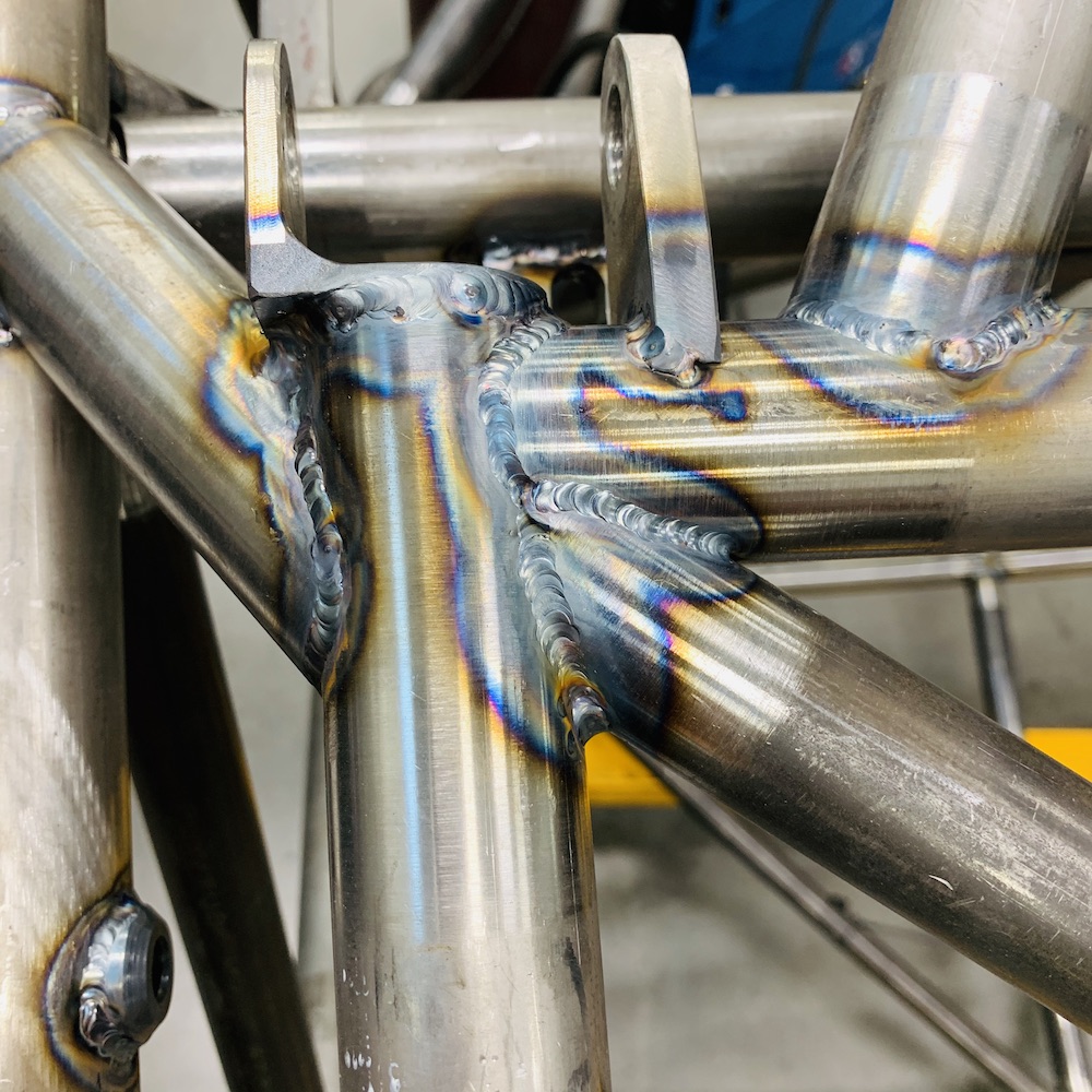
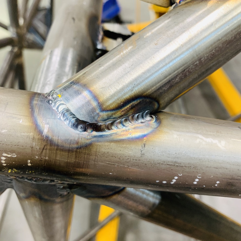
One TIG welded Mini-Raptor chassis:
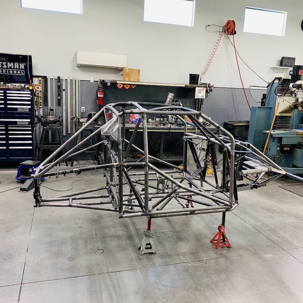
Time to start the sheeting process so I can seal the cabin and get a skid plate made.
One of the UTV parts mfgs in the Phx area on IG or FB offered to help make one and now I can't find the correspondence so if you happen to read this, hit me up as now's the perfect time.
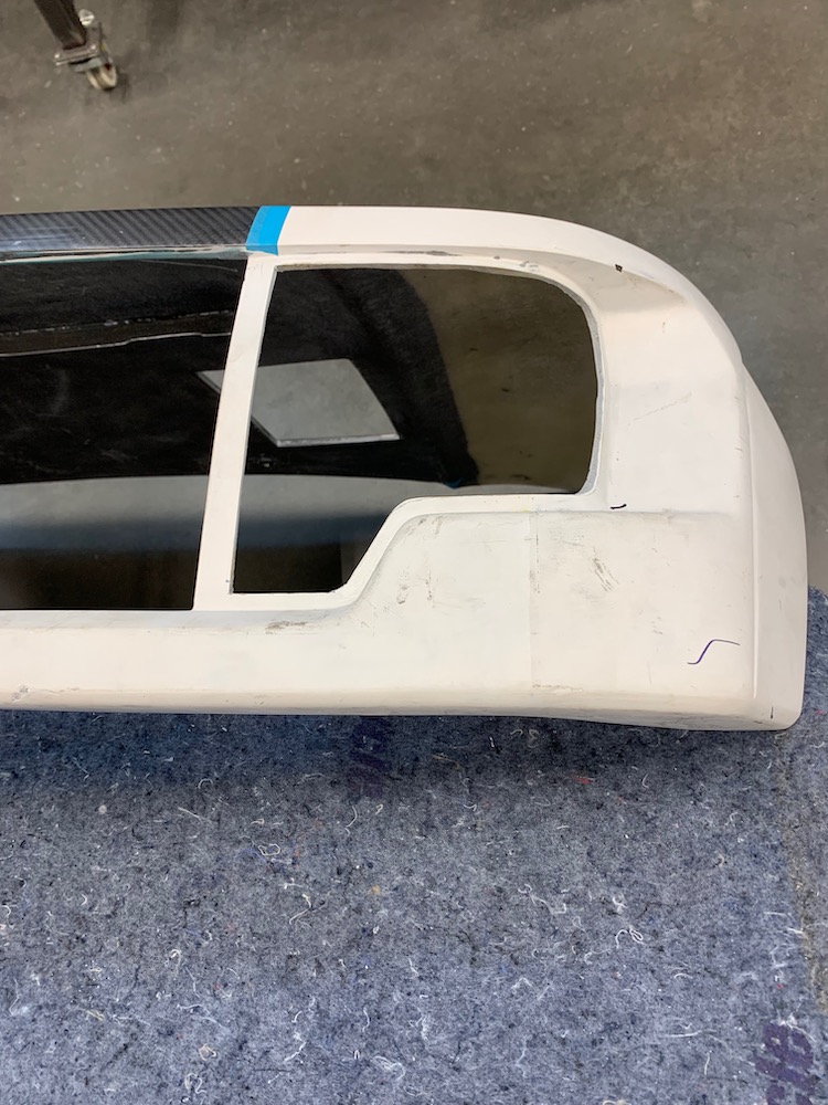
Body Panel work begins.
I've had those self contained, spring loaded Dzus buttons in a box for twenty years (used them when I was stadium racing). Guess it's time to put them to use. They'll get rid of the "Where'd those buttons go?" issue - to which I've asked myself a couple times today "Where'd I put those?" - oh, they're in the panel. Duh...

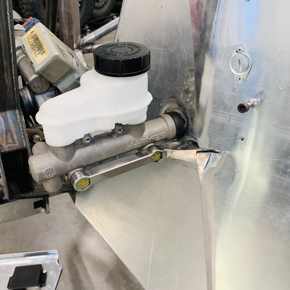
Had to make the driver's side two separate pieces because of the master cylinder and its mount.
Right side will be a single piece.
Nov 5, 2019
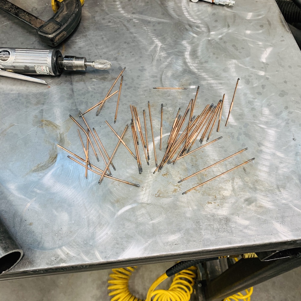
Had someone on the FB page ask how many sticks of filler rod were used in welding up the chassis. Thus far 43.
Dimple clearance in the panel for the sealing cap on the master cylinder's input shaft. The side in the first pic looks distorted because of the plastic stuff on the aluminum sheeting that's pulled loose during the dimple pressing.
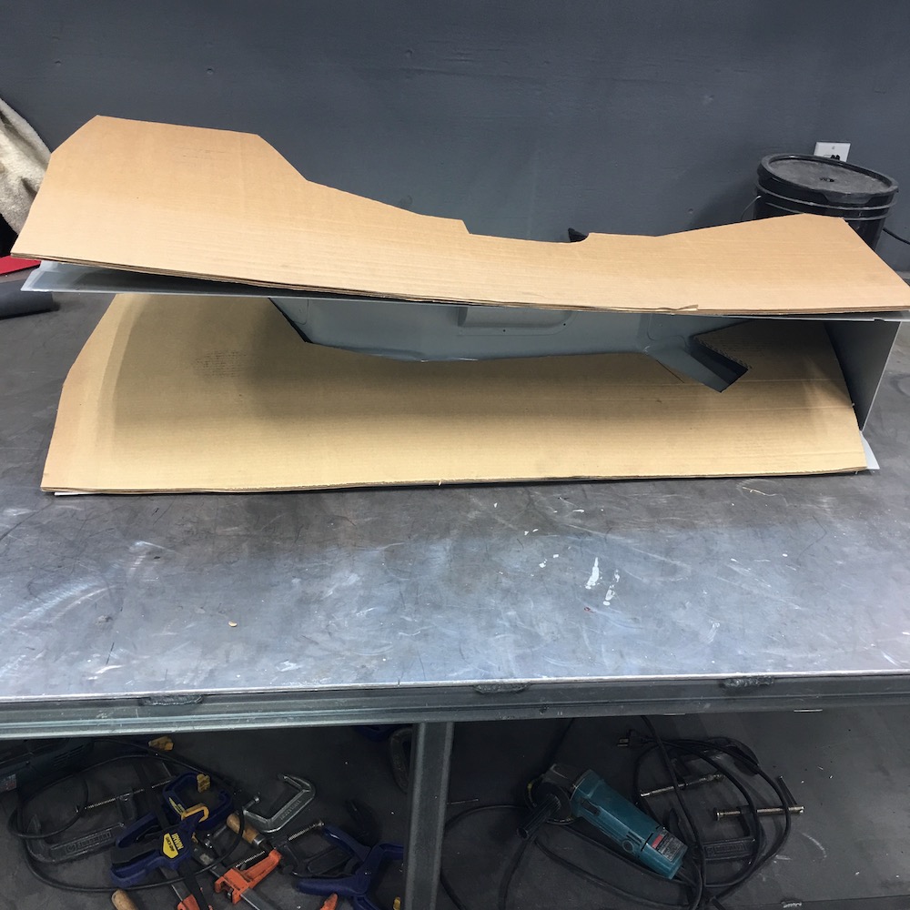
Old school CAD - Cardboard Aided Design.

The panel is now about 75% finished in aluminum.
Nov 11, 2019
Panel darn near snaps in place. The center piece is still the original that's getting changed out.
Here's another shot with the new center in place (see the Dzus tabs?)
Decided to move all the electronics off of the fire wall so I can remove them if need be w/o dealing with wires. Made a little sub panel that now does the job.
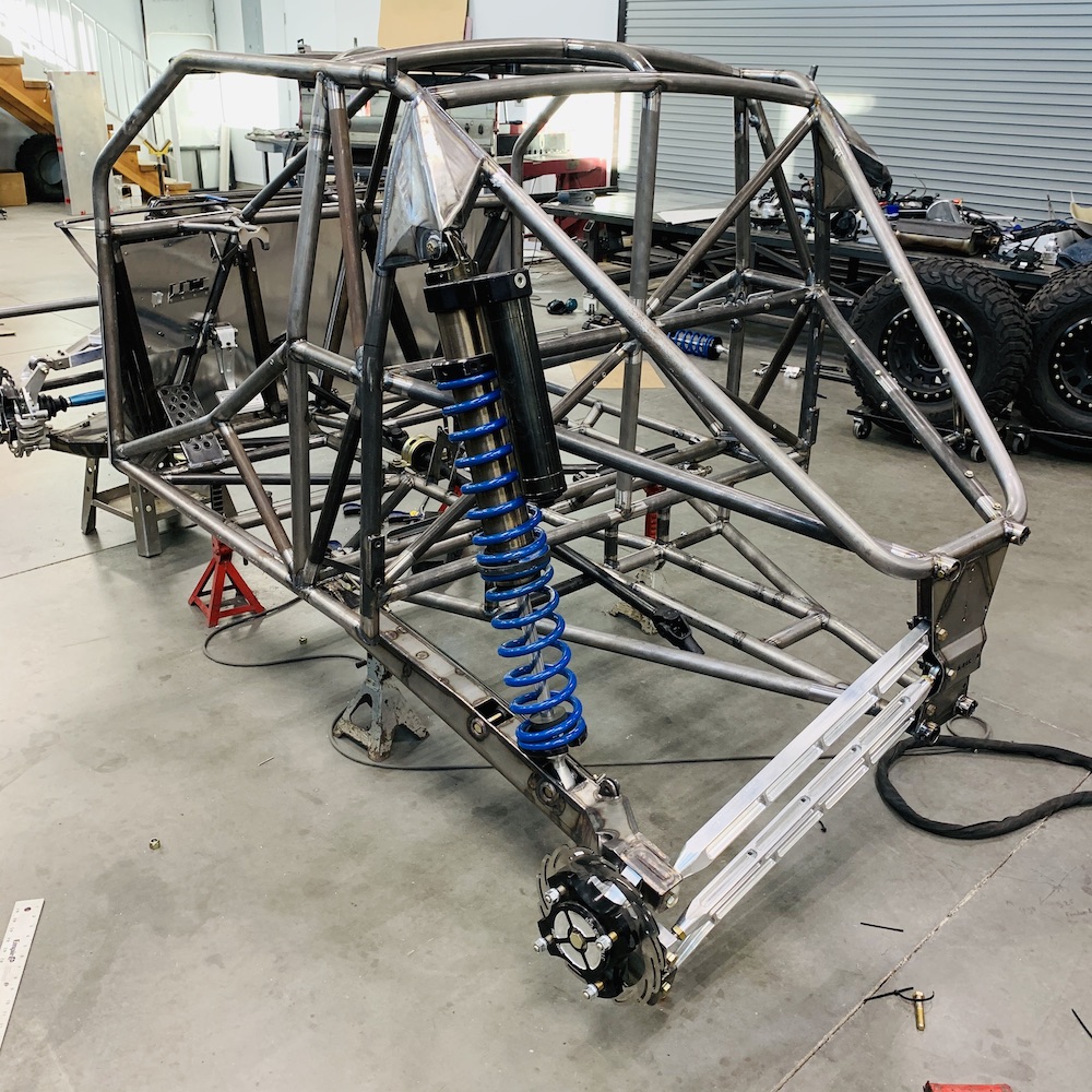
Inside cabin shot:
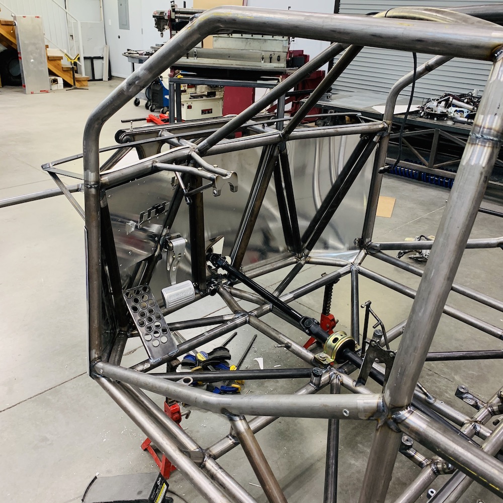
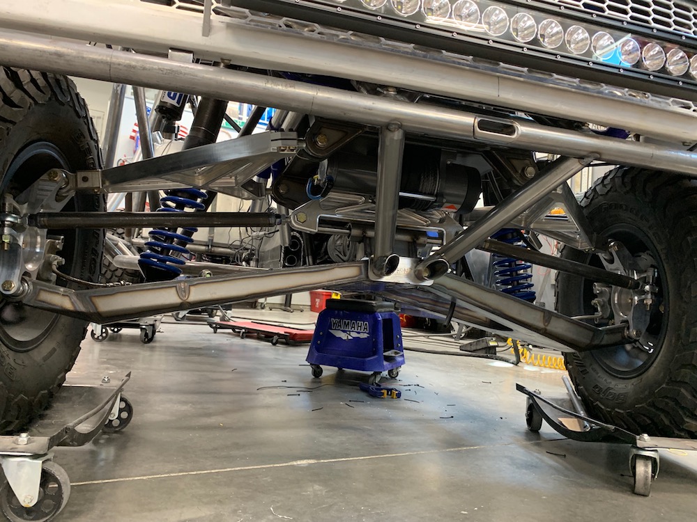
First time test fitting the Knine Racing axle up in front. It fits PERFECTLY. Put the suspension on to start getting an idea of where my limit straps will be located. Originally I was going to mount them to the upper frame tube that runs through the top of the fire wall. Of course this won't work - master cylinder is right in the middle of the line between the two points. Crap. So I'll make a mount that uses the back, upper a-arm mounting bolts.
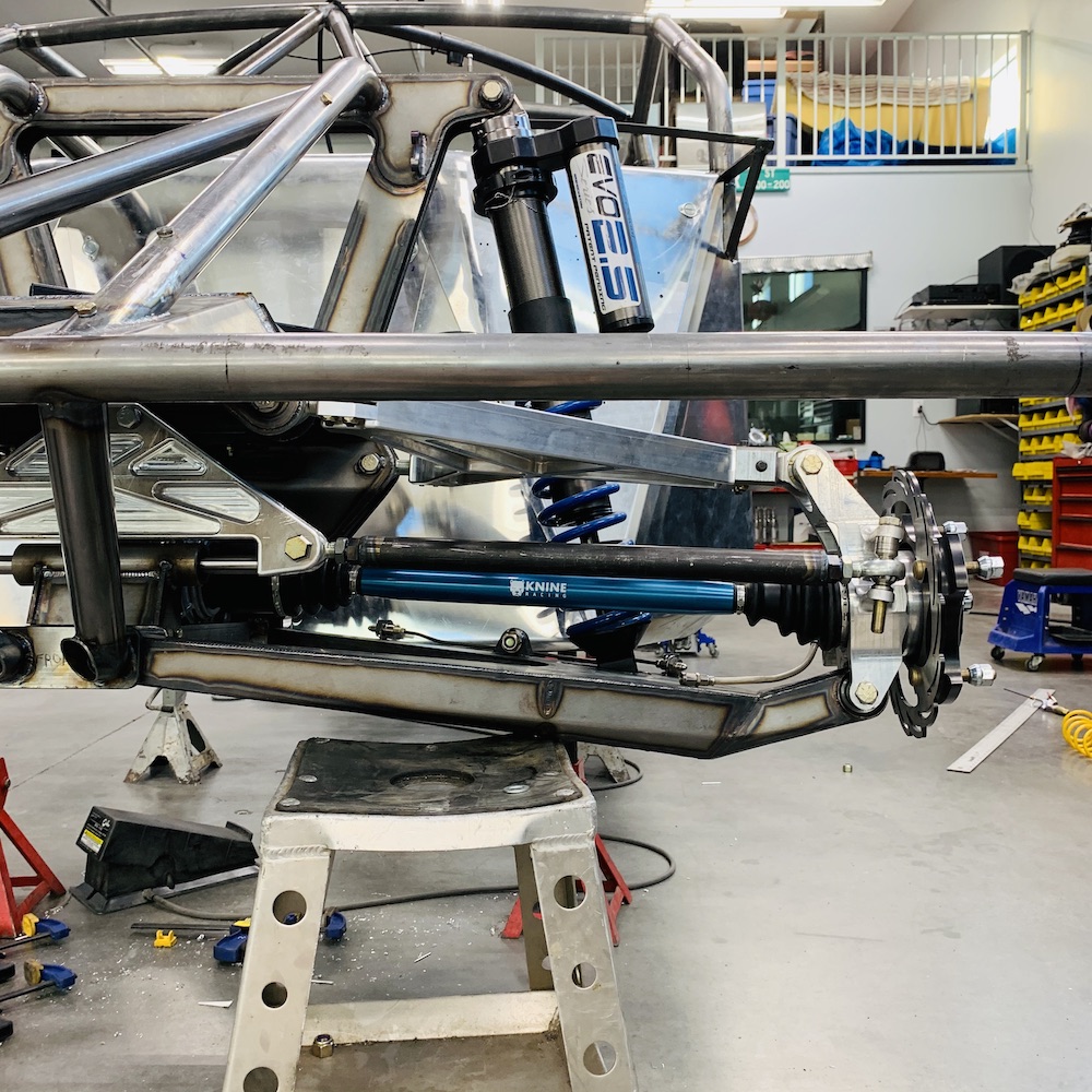
Drooped to full shock extension (actually outside design parameters) the spindle toes out a bunch and the camber goes way up.
Move it up about an inch to the designed full droop and the toe and camber go right back to where they're supposed to be.
Because of my mid build design change (last year?) on the rear links there are binding issues. Everything was originally designed around using heims on the ends of the transverse links. No clearance issues what so ever. I had to go and get all fancy and machine out billet transverse links instead and caused all sorts of headaches.
So I sat there with a grinder and started cycling and grinding. I'm pleased to say that the suspension droops fully out to full shock extension and I'll be using limit straps to pull out about an inch or so of final droop. No binding, no issues (I hope) now.
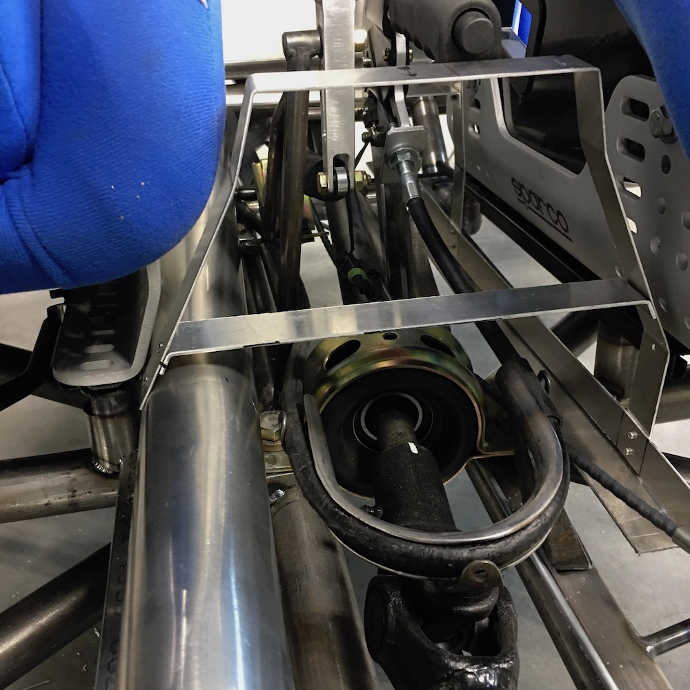
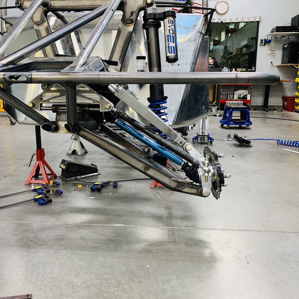
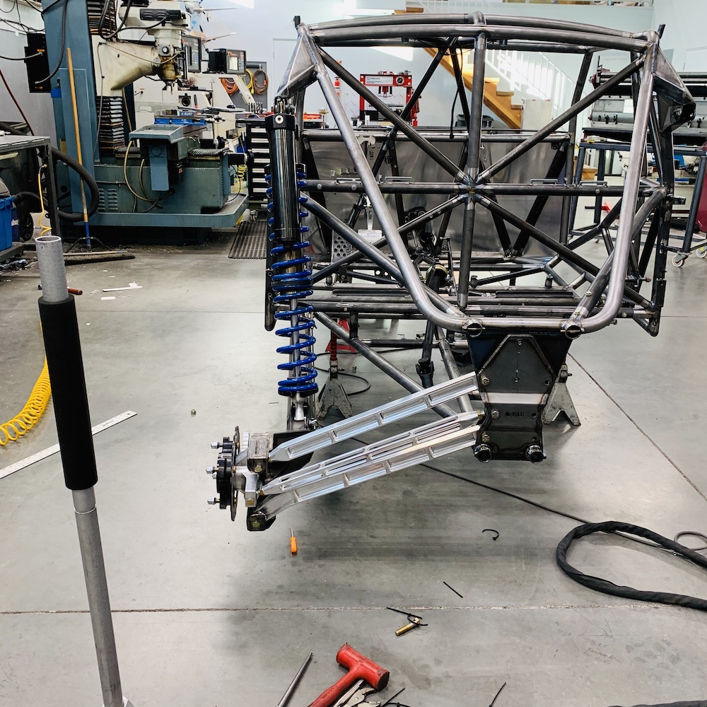
Rear quarter view of the suspension in bound droop. Doesn't give a very good point of view as to how far off the ground the rear carrier is hanging.
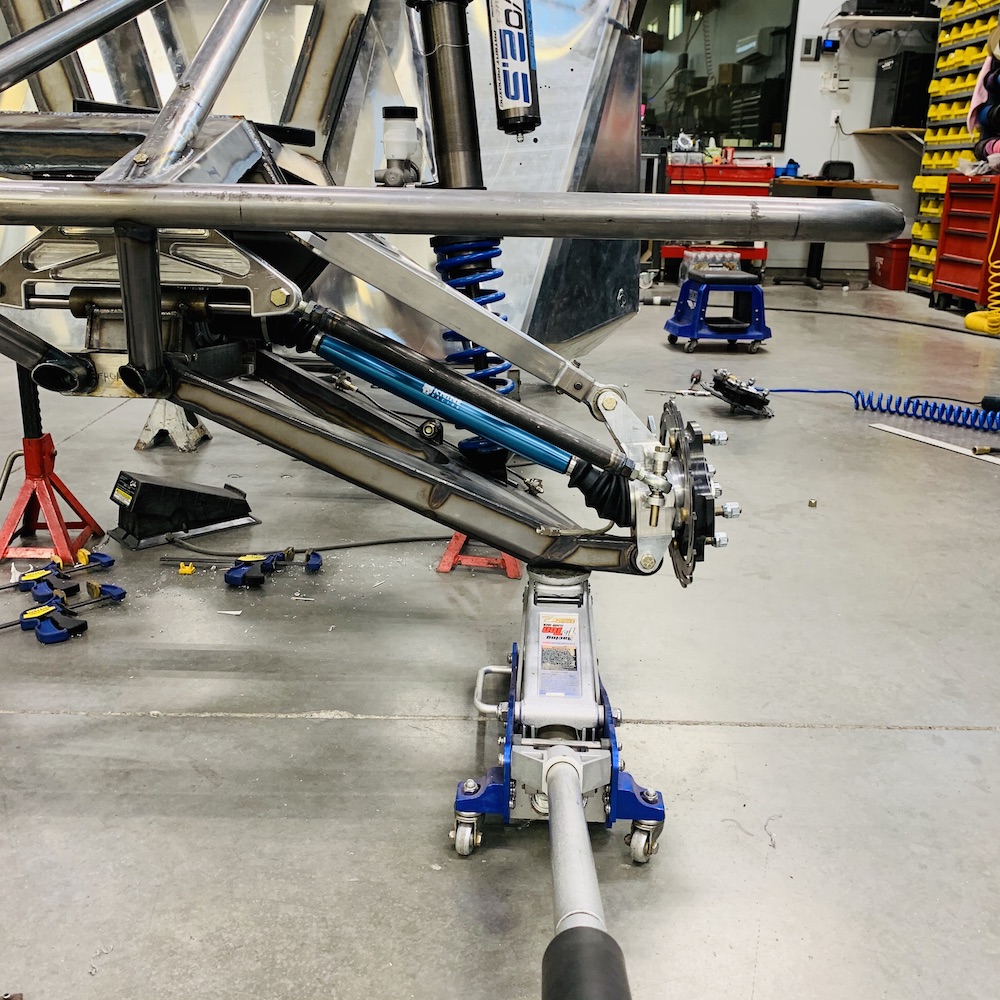
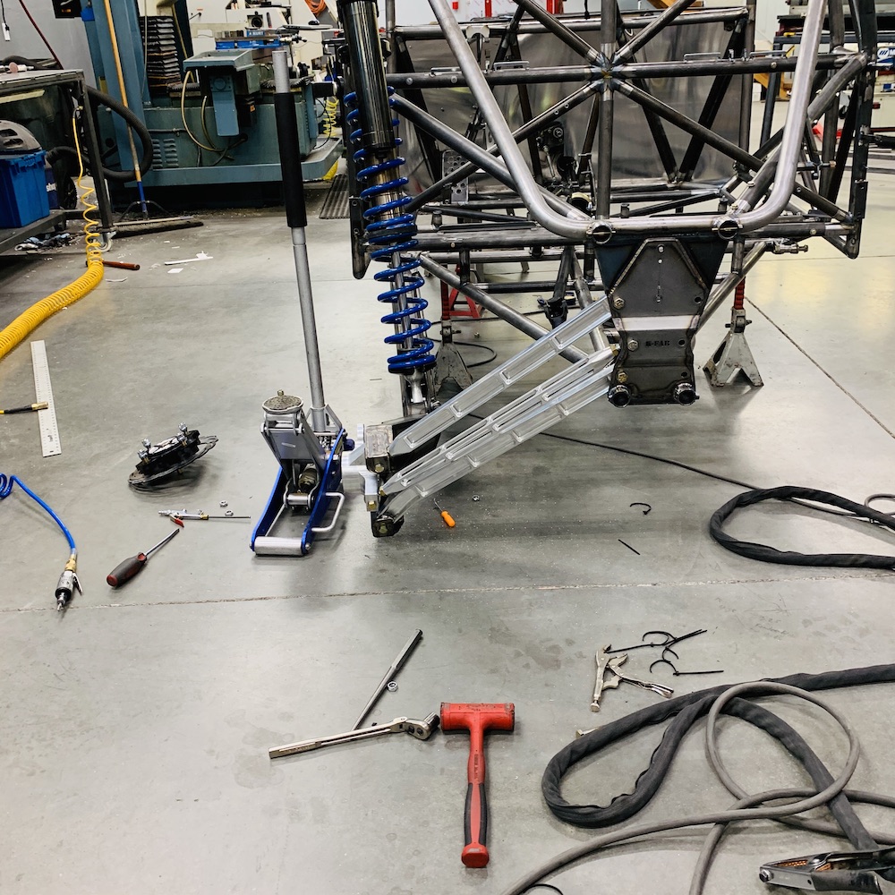
Here you can see that there's about five or so inches between the floor and the rear of the trailing arm. The shock has about three inches of preload in it.
Final product - all the links can move freely and the shock is fully extended. There's an inch of clearance between the floor and arm now. Gonna have to do the same to the other side (it's already been massaged a bit but I'm pretty sure there's more to be had.)
Nov 16, 2019
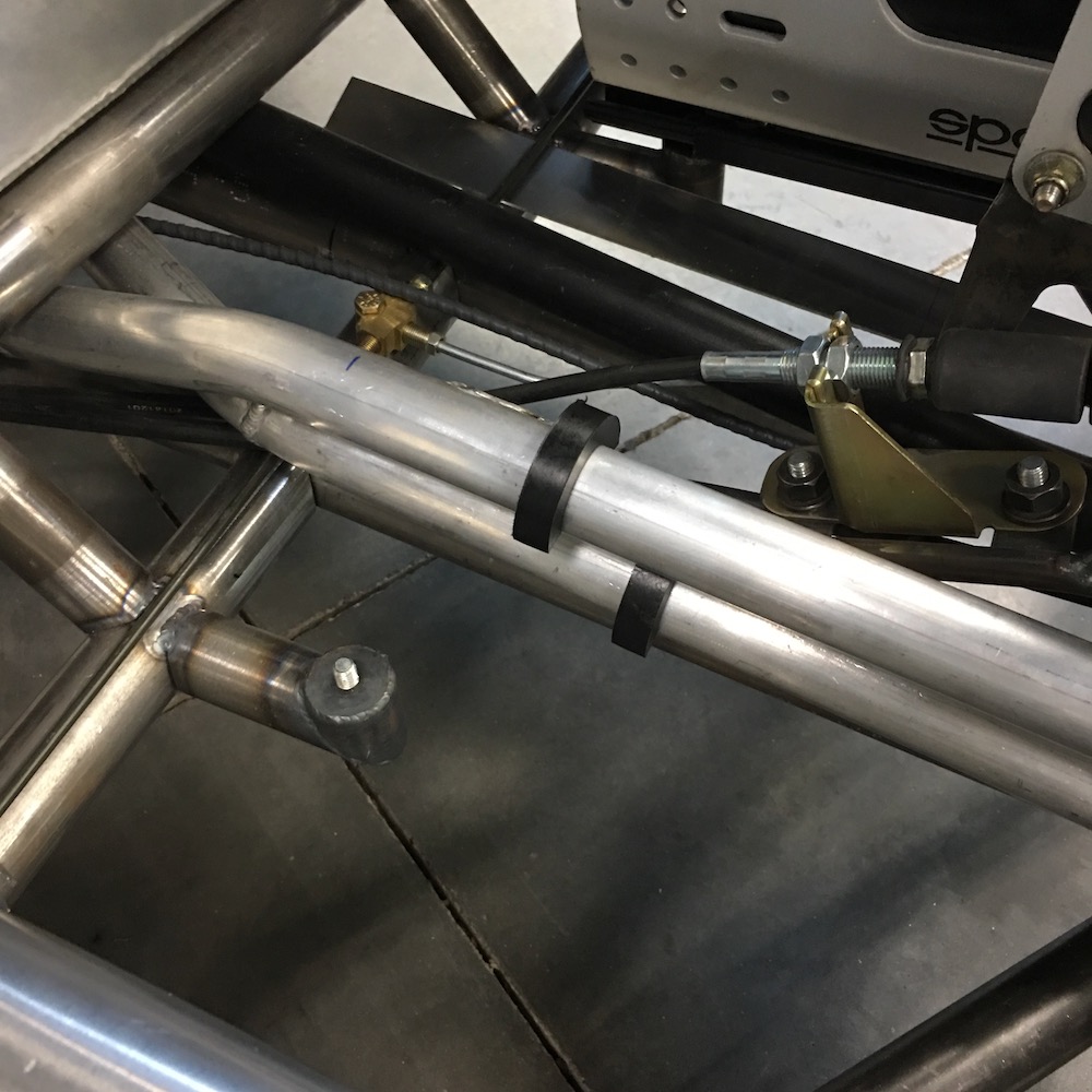
Rear firewall installed.
I keep going between the front and rear now that I'm running all the plumbing and drive line stuff.
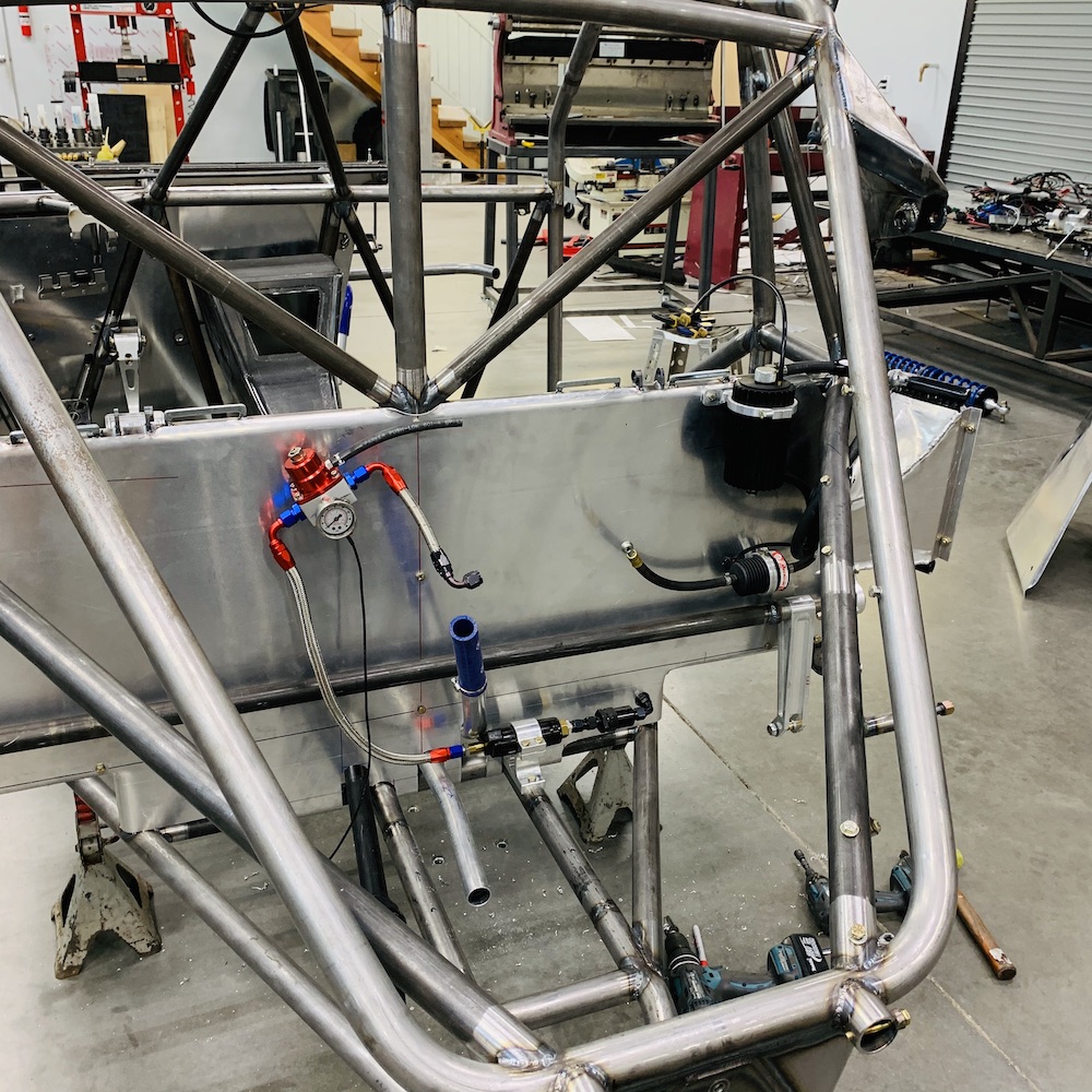
So I get to the front where the coolant lines run through the firewall and start doing the plumbing there. All is good, all is fitting, all is there, uh...

Okay, everything came off the MR and was put on the table in order, where are the lower two 45 degree tubes???? These are the same tubes that were lost in Customs last year (egad, it's been that long!) WHERE ARE MY F&*#$$# TUBES???See - everything in an orderly pile!

And come to think about it, where is my 1/4" drive floppy wrench? It appears that the injectors, my tubes, wrench and appendix are on the lam.
First thing I did was look for my 10 mm sockets - all accounted for, no wrench. Damn

So I started back tracking and looking and hunting and realized I'd tossed the tubes into spare tube box that I'd put away. Bingo, two tubes, sitting there staring at me in it. Like the injectors, I grabbed them and immediately started putting them in place.
Also, after opening and closing the drawer that has the crescent wrenches in it half a dozen times I actually look in it and there's my floppy drive hanging out with a lowly 8mm socket - guess it didn't want the rest of the wrenches knowing what it was up to.
Injectors and appendix are still missing.
Anyhow...This reassembly will lead up to the test runs. Everything gets put in place, made sure it's working and hopefully I'll have a running (but not finished) Mini-Raptor by the end of the year.
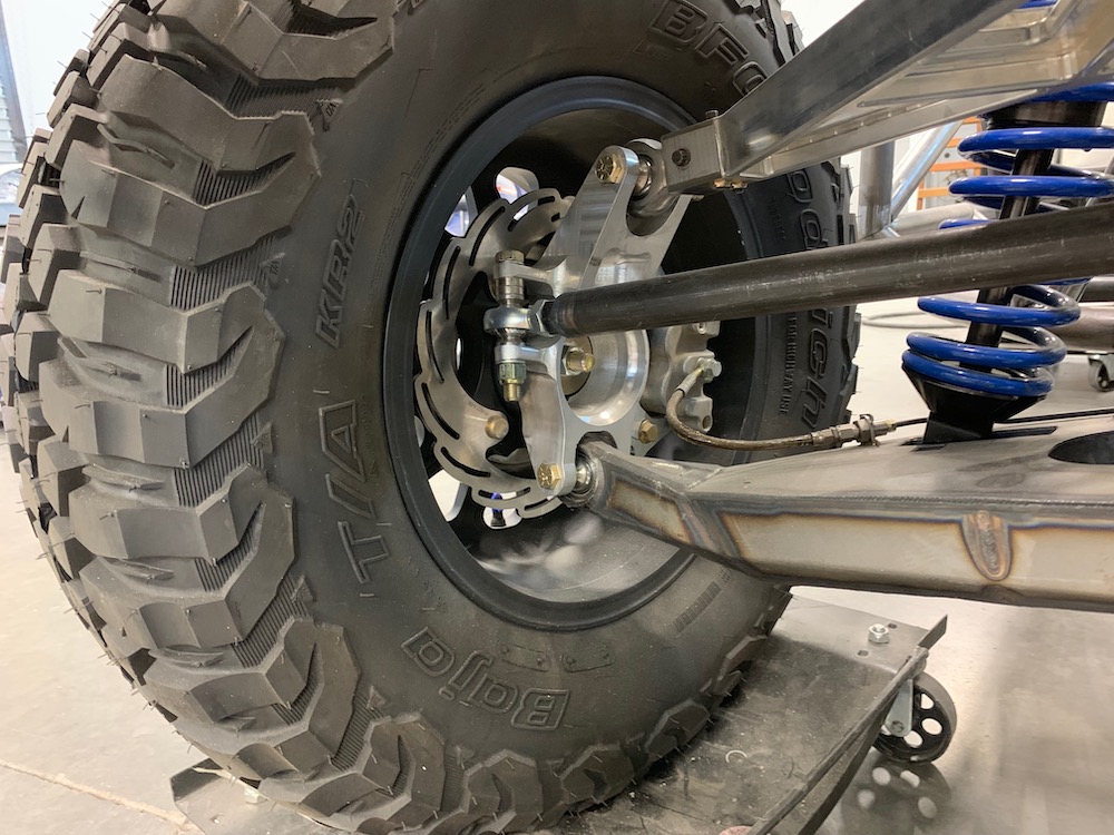
Knine Racing custom 300M XP 1000 axles going in place:
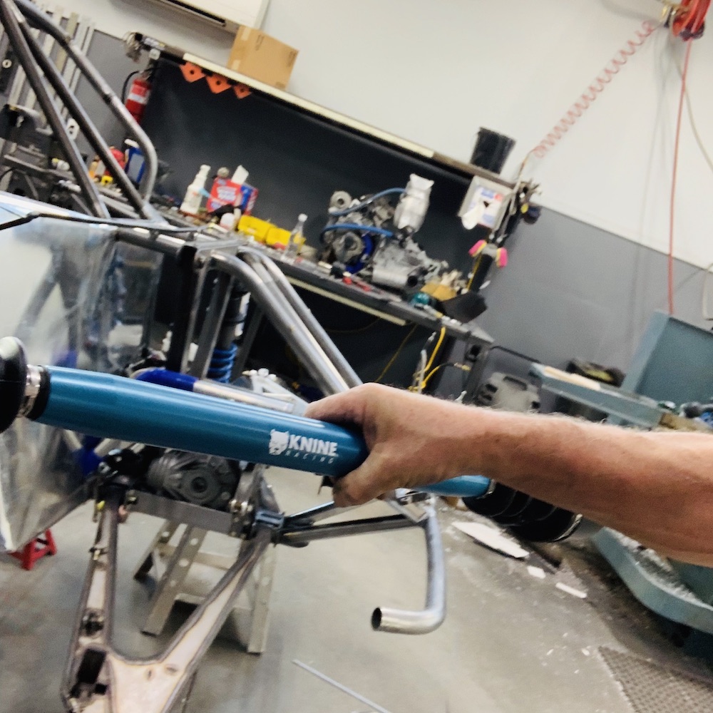
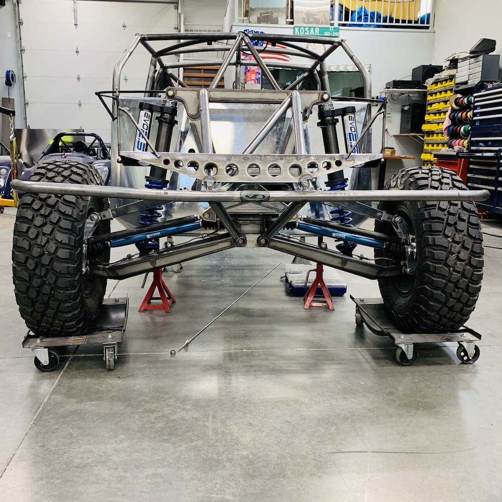
Fully assembled front end.
Had a discussion with Ben from Knine today. He's coming to Phoenix in January to do some custom X3 Mini-Raptor work for a client. We decided we'd get together and I'm gonna take him out in the desert and show him some of the local beauty. Timing should be just about right - looks like Ben gets to go on the maiden voyage if all works out. Pretty cool if it does.">
Dec 12, 2019
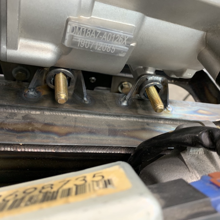
Back from Thanksgiving vacation and then having to be responsible. I get to play again. Yay!Got the 12v AC compressor mounted today. It will be getting a shroud and possibly ducting from the ac to keep it cool. It's behind the radiators and it's not supposed to like being above 70C (158F) so I'll make sure it's happy.
Nuuuuuuuut Pockets.
Dec 17, 2019
As I reassemble for first run I'm testing everything, making sure all is good, etc..
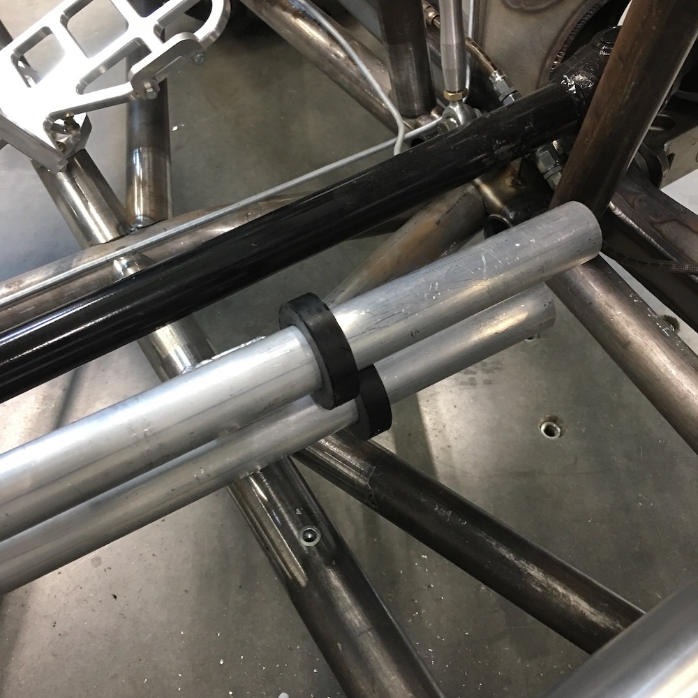
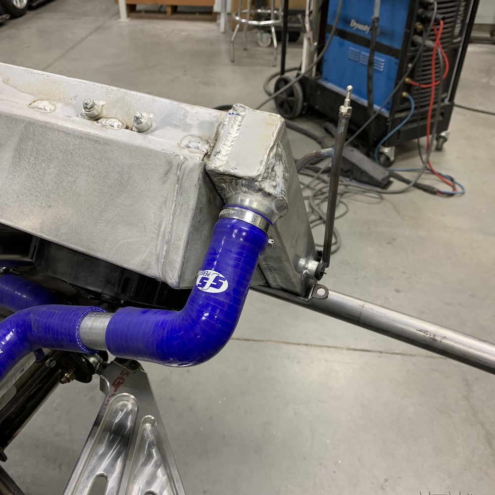
Presently working on getting the cooling system installed.
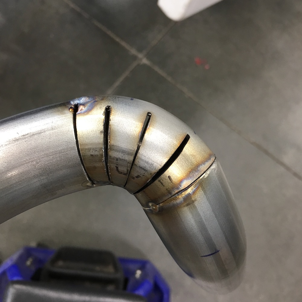
I've put rolled in beads on the end of each tube, checked all my welds and have found pin holes here and there. All tubes are now sound.
Check.
So...
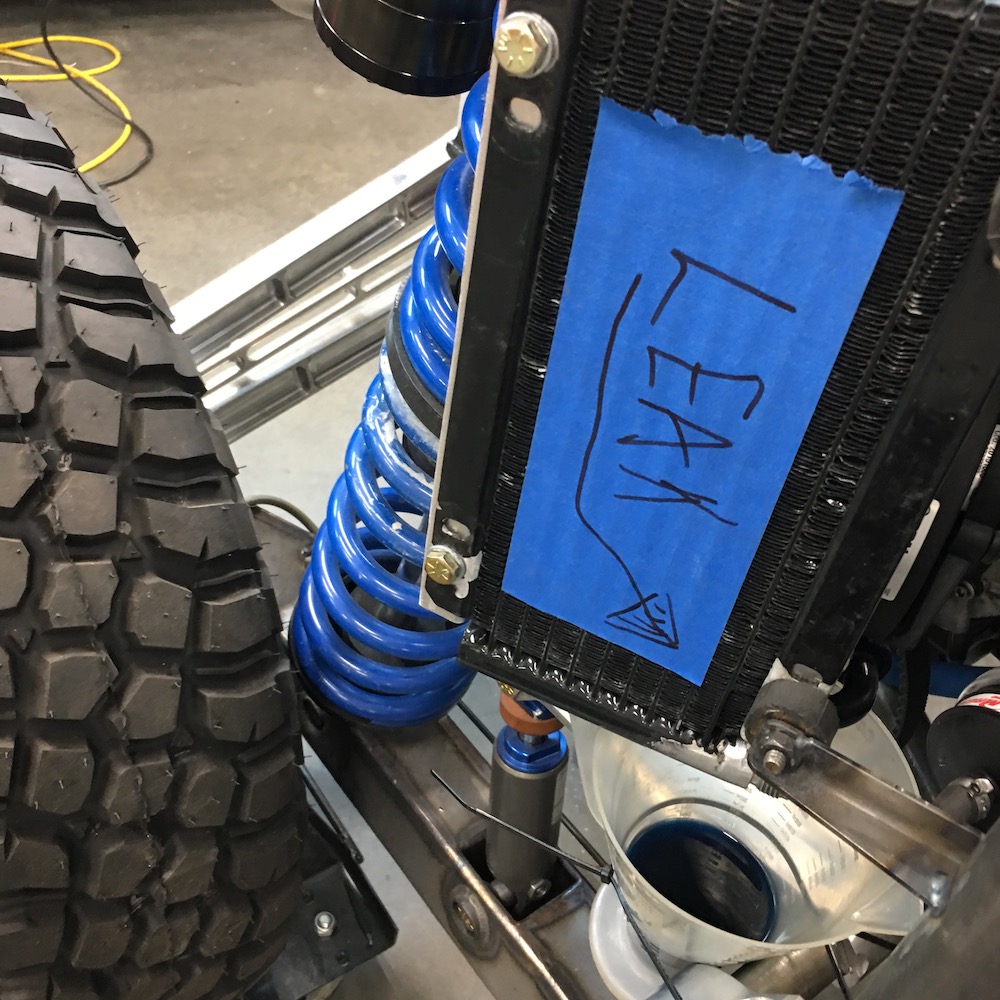
Off to radiator land. I've had issues welding on the radiator. My TIG skills have come up and so I decide it's time to tackle the leaks.
Yup, quite a few little pin holes here and there and of course the two largest are at the remote thermostat housing that everyone picked on me for placement (from someone's suggestion...).
There they are: Between the housing and the shroud. Perfect placement if you don't want to be able to weld on them. Crap.
The thermostat housing is a two piece screw together unit. Nice fine threads. (and some of you probably know this road before I tell the tale)
I start melting stuff together, puddle here, puddle there, pin hole removed, pin hole found, removed. I'd cool off the neck of the radiator housing with the blow gun, trying to be patient and not get it cool too quickly. Once cool I'd screw it together and pressurize the system to look for more leaks.
Repeat, repeat, repeat and then that one time not get it quite cool enough before assembly. Goes together just fine. Pressure test, fix next hole, unscre... uh, unscr... Oh shit. The thing seized.
I now have a nice bung that's well sealed on a well sealed radiator so you guys that didn't like my thermostat housing can quit bitching. LOL
Yes, it is MELTED in place. It doesn't leak and nobody will ever see it. [smilie=moon.gif]
The new OEM thermostat is on the way. I'm going to make a remote in line thermostat housing that sits just off of the engine at the pump output. Basically where Yamaha puts the stocker but I'm not doing the bypass circuit.
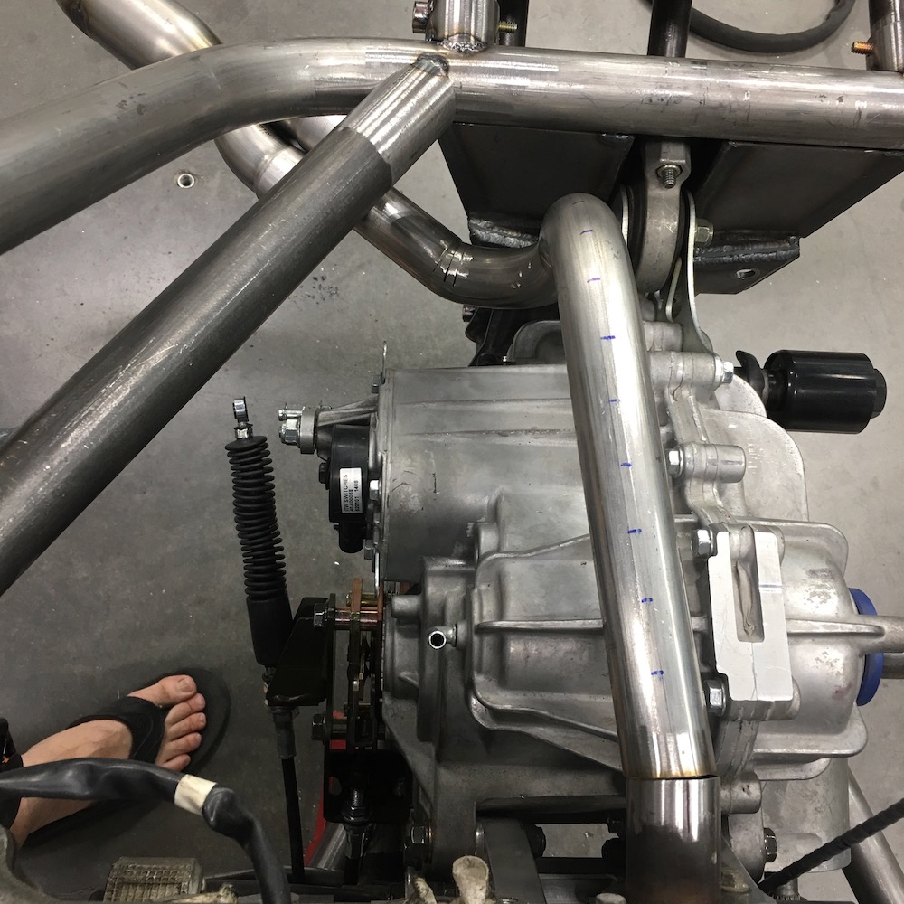
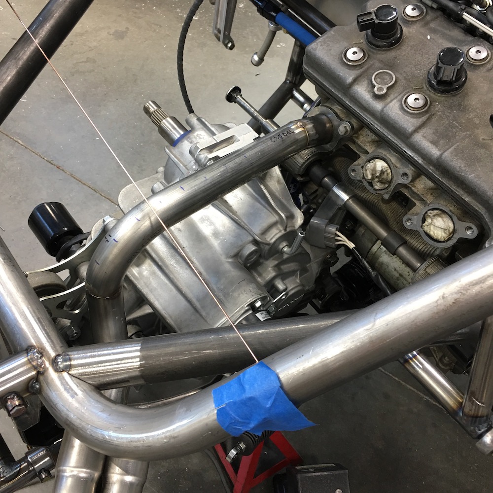
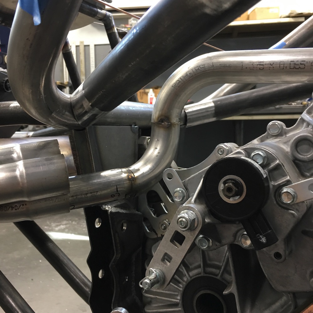
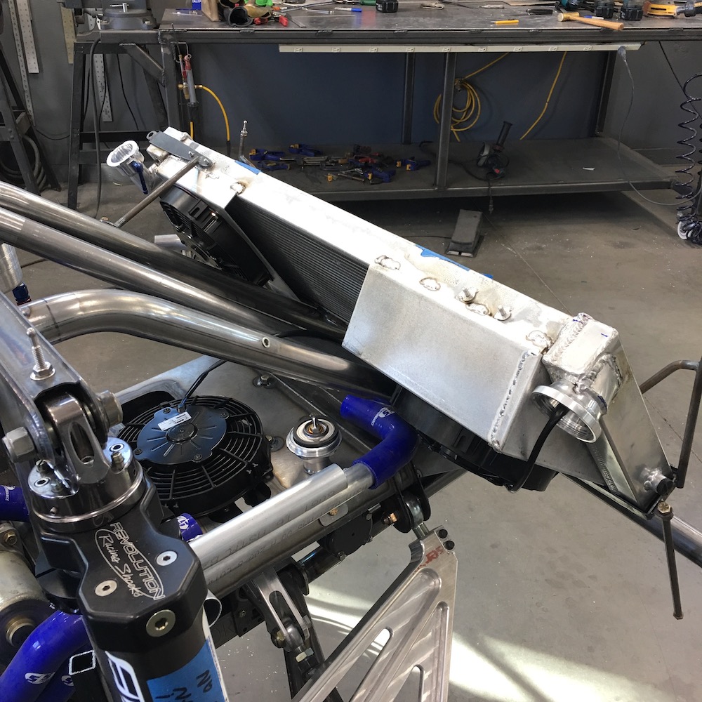
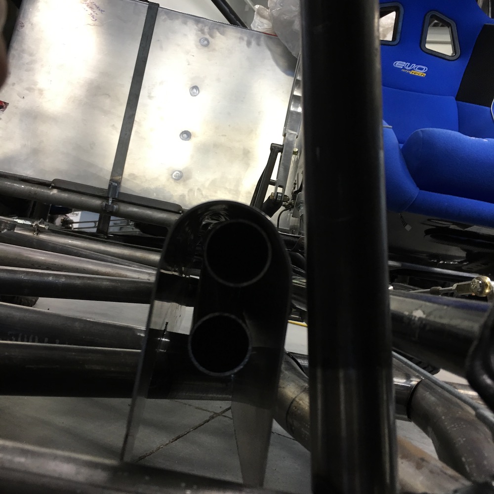
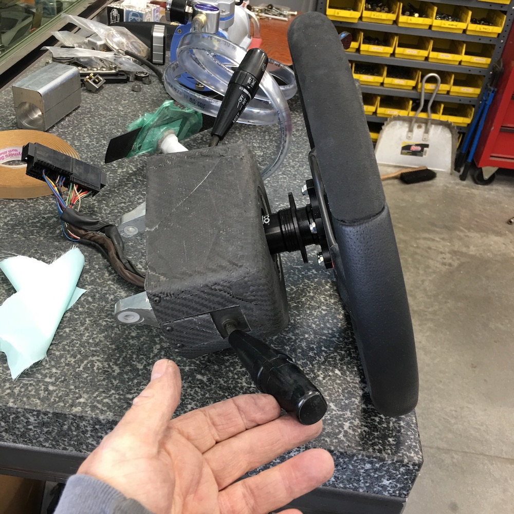
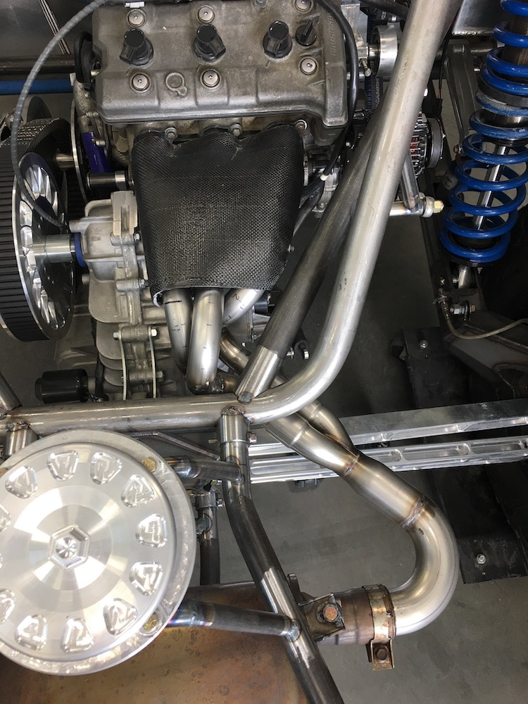
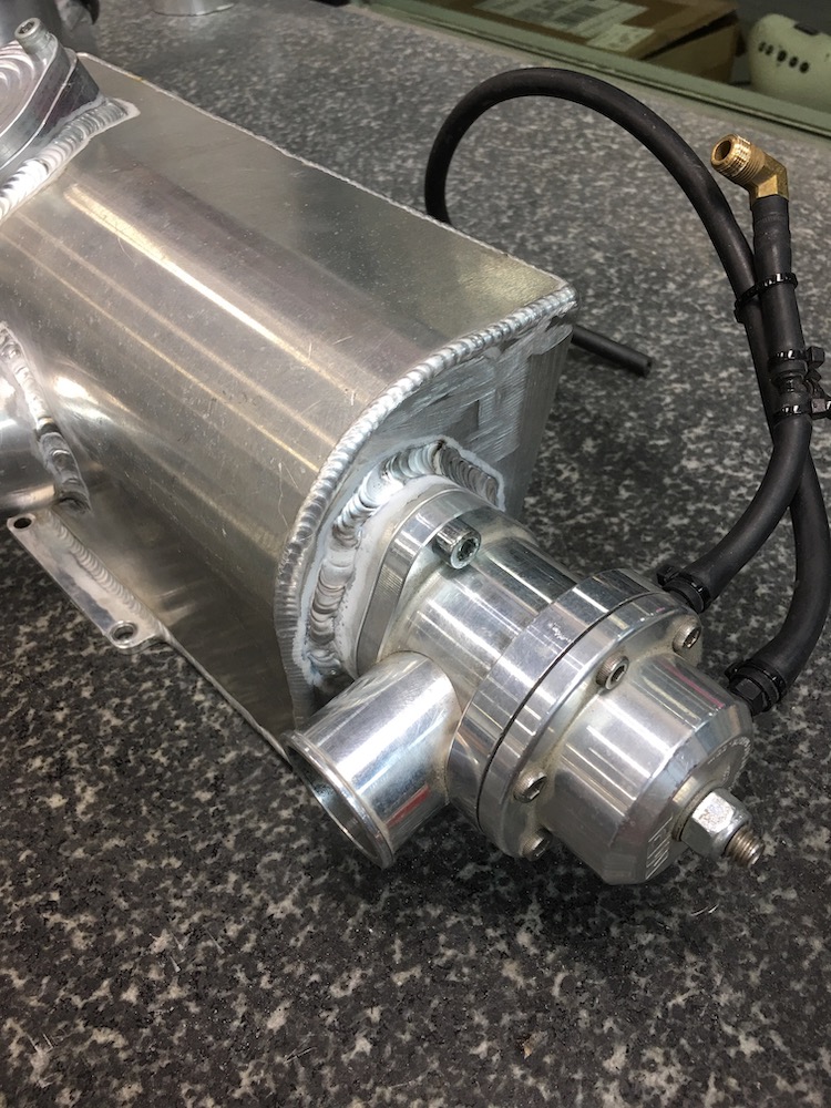
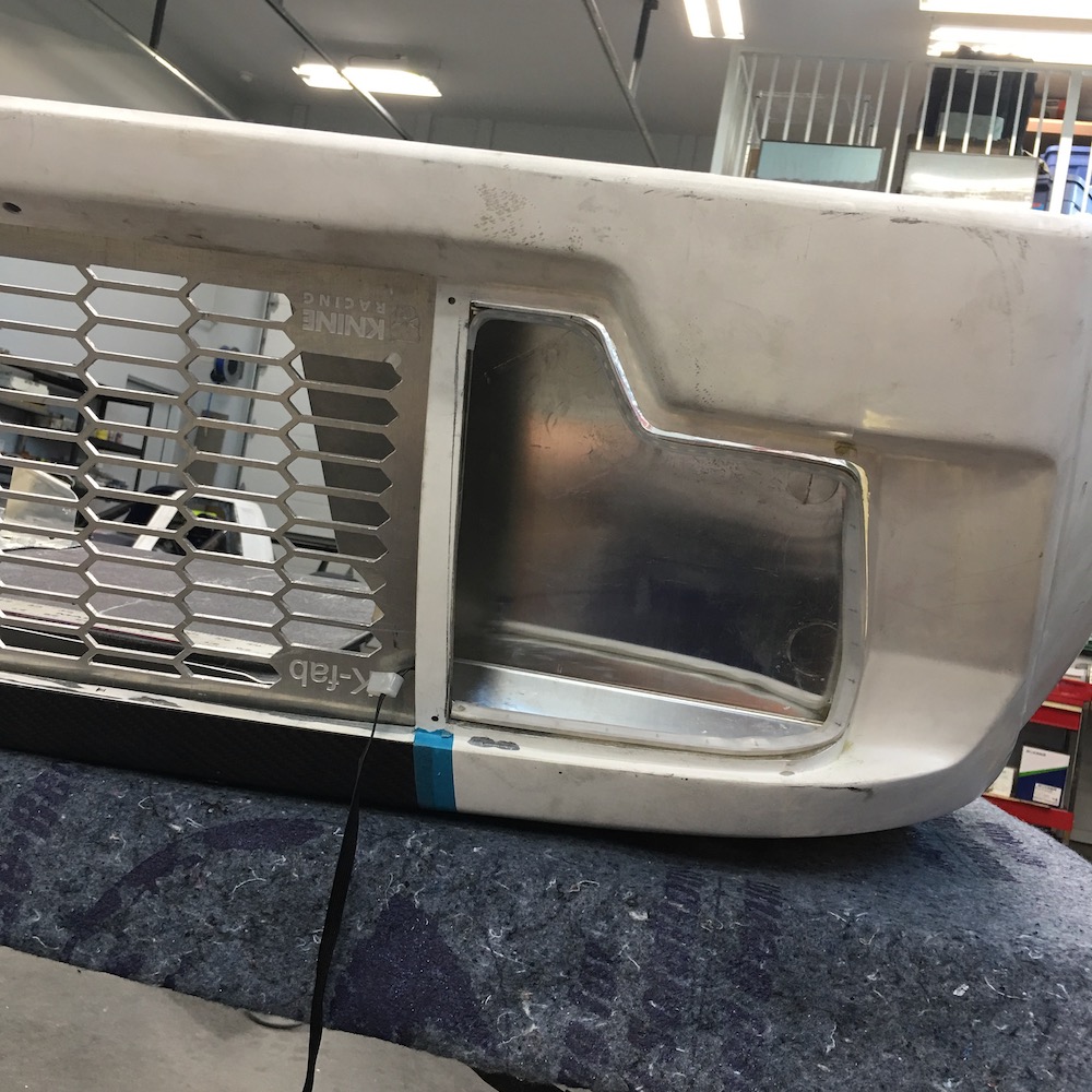
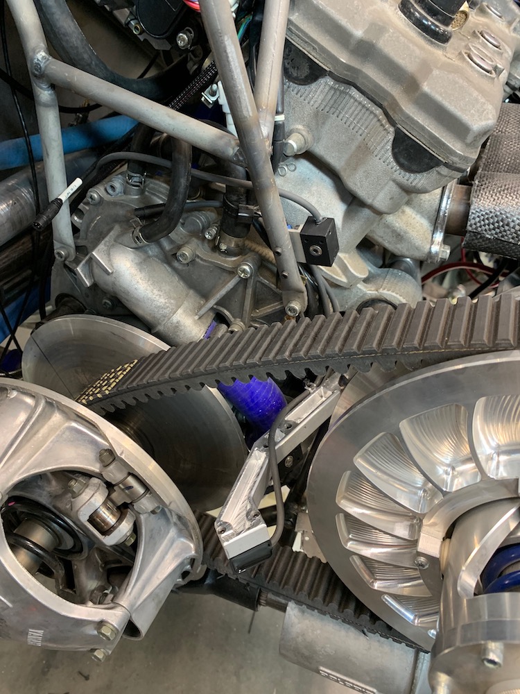
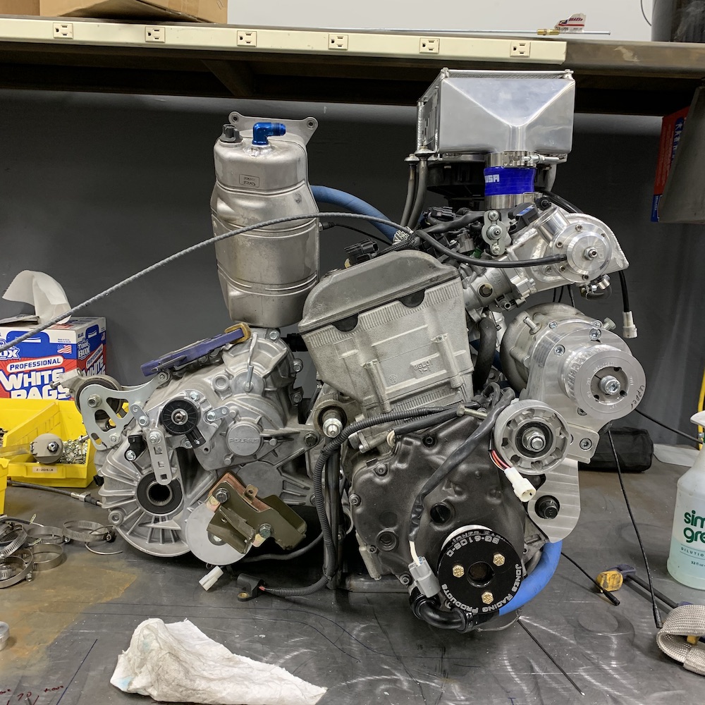
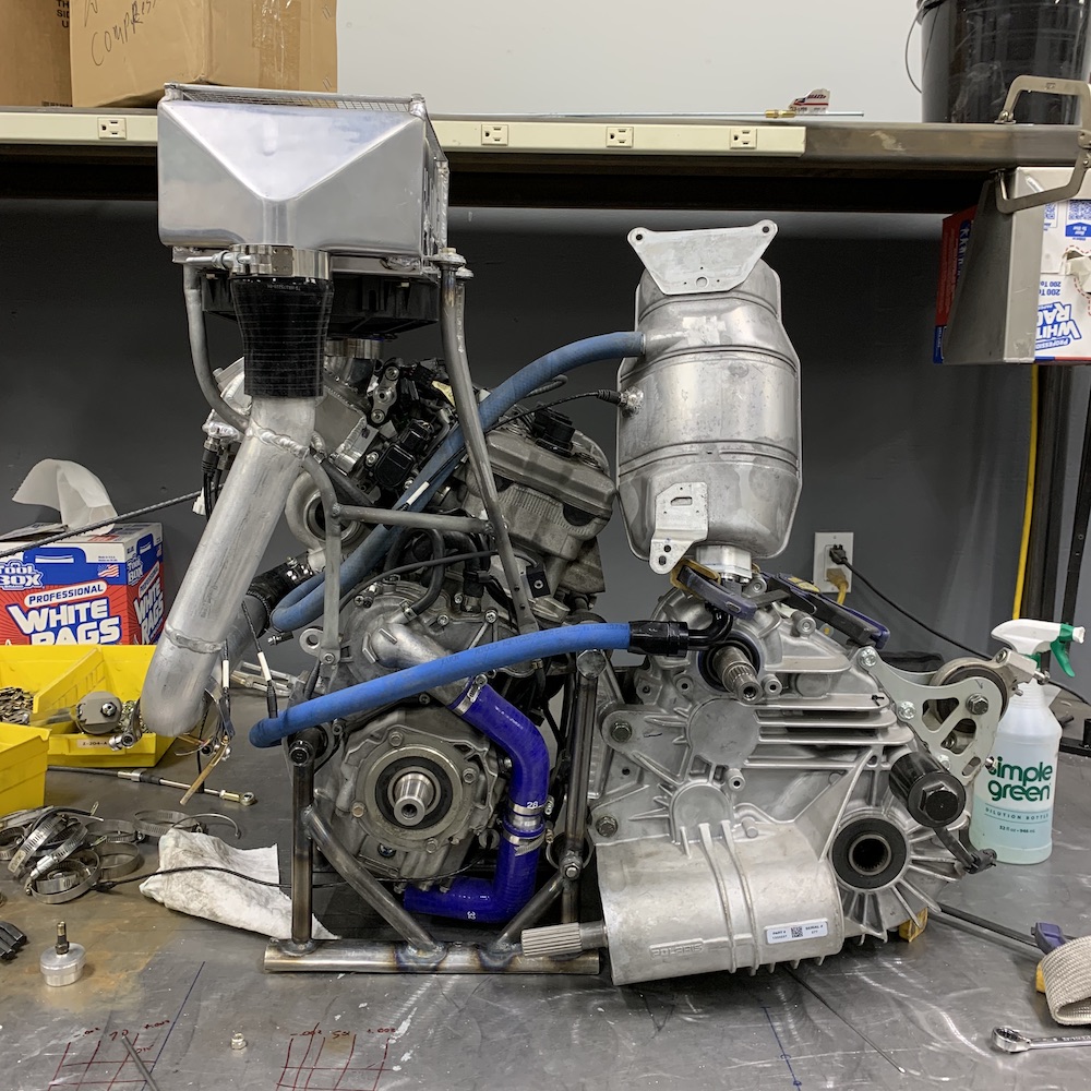
While I'm playing with toooobing I decided to assemble the intake system with the powerplant on the bench. It's quite tight in the chassis and I've been wanting to check a couple of clearance areas.
I need to figure out a support for the tube that goes between the supercharger's output and the input of the intercooler. Intercooler needs to sit flatter too. Now that I have the main pieces in place I can massage the ugly frame that holds the intercooler in place.
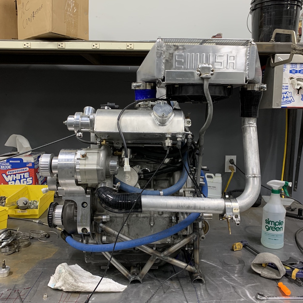
Couple of side shots for grins. The oil tank is just hanging around - it gets mounted to the firewall.
Dec 21, 2019
I've gathered all the info above, printed it and stuck it to the side of the welder. Thank you!!!
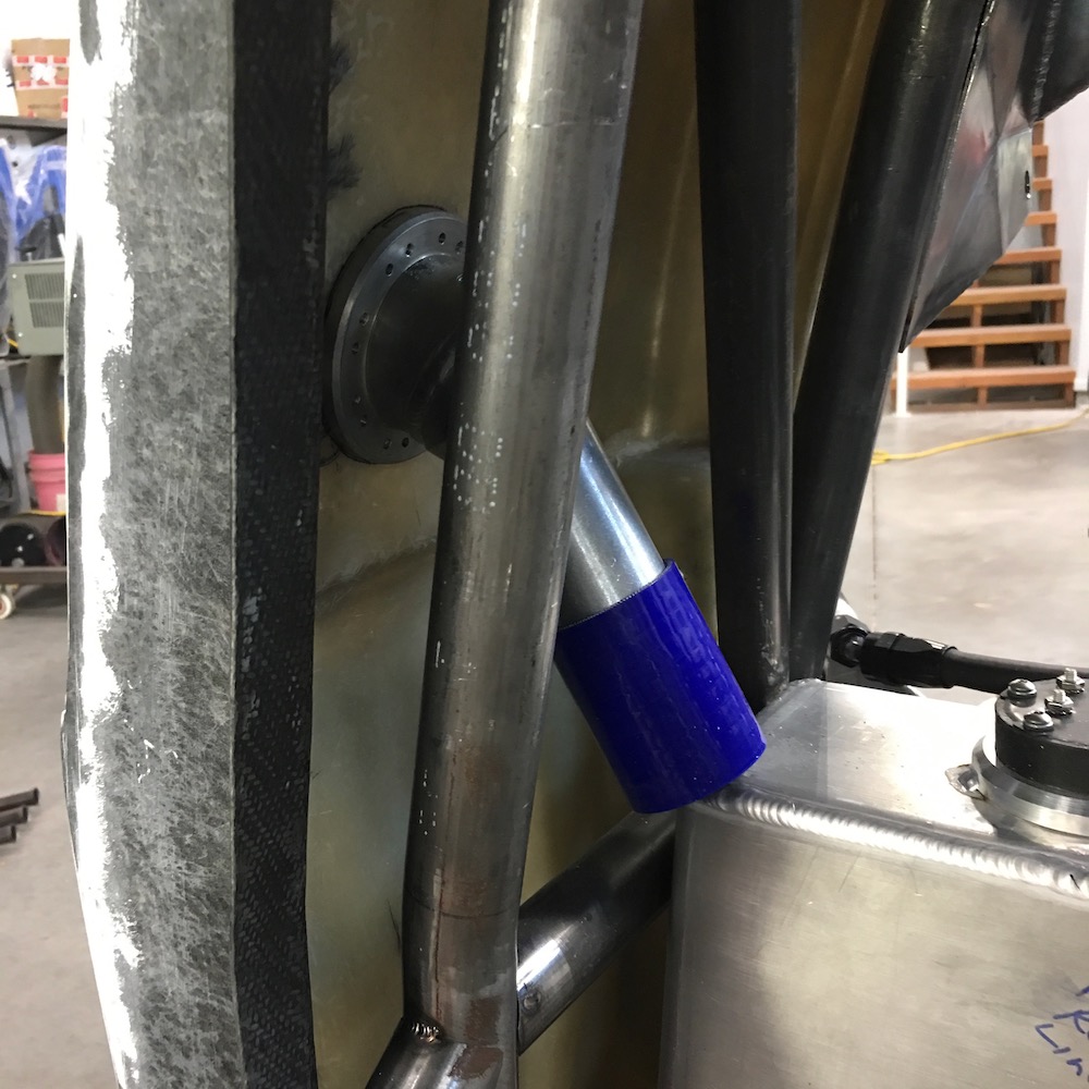
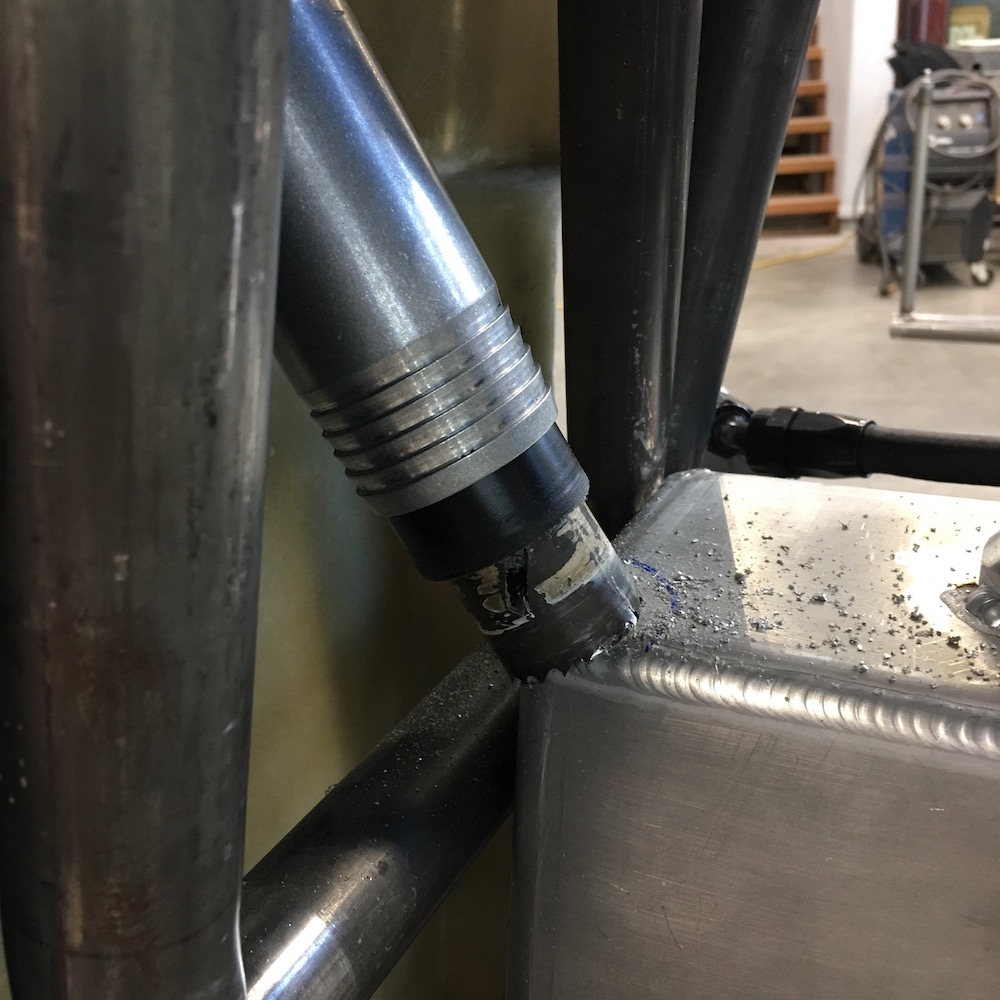
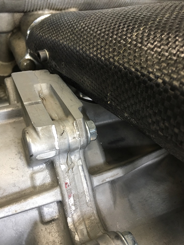
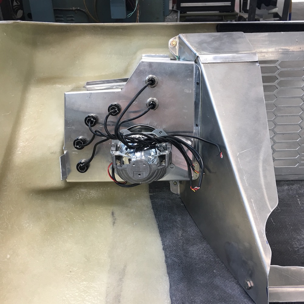
So the setup on the sled has the plenum box held against the engine with a pair of big ass springs that go to the chassis. The normally aspirated engine doesn't have issues with the throttle bodies getting blown off - they're under vacuum. Put 8 pounds of boost through them and the stock mounts can let go and blow the intake system off. I don't have a sled chassis or can I find the springs so I decided that I'd get fancy. Why not, right? Whole MR is billet accessories.
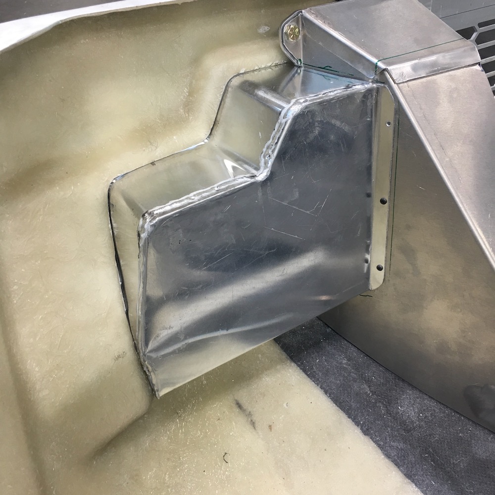
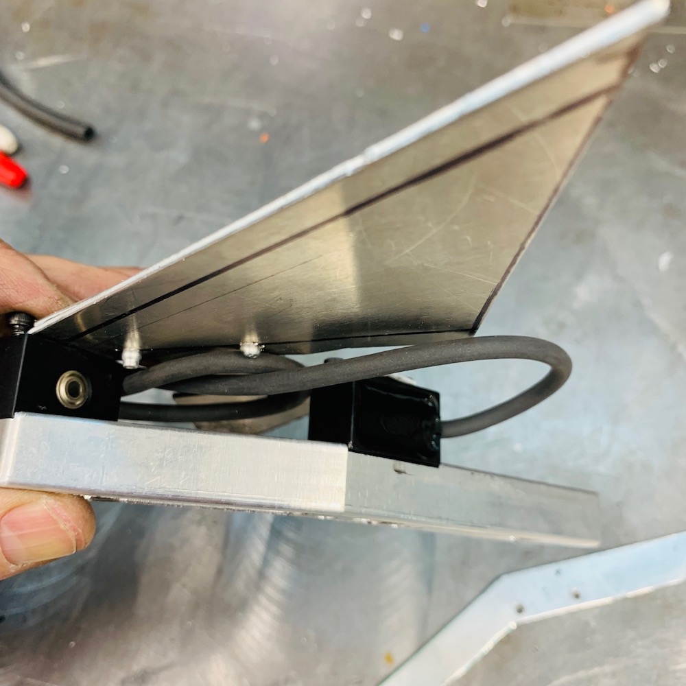
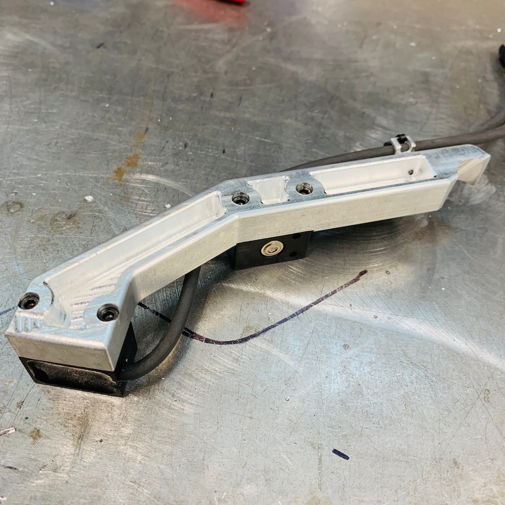
Time to make a couple of supports that hold the box to the engine instead of the chassis. Problem is where to attach to the engine?
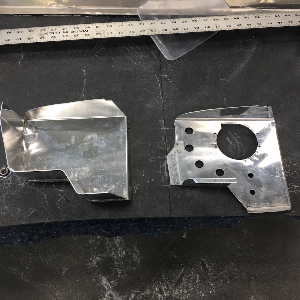
One side was a gimme - has a bolt that holds the outside part of the head down on the jugs. Easy enough - whipped this little piece out:
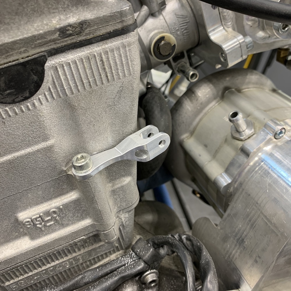
The fork that the heim joint fits in is angled inwards 15 degrees so it points in the general direction of its friend, that will be attached to the box.
They'll go in here like this (two days ago - prior to getting the right heims):
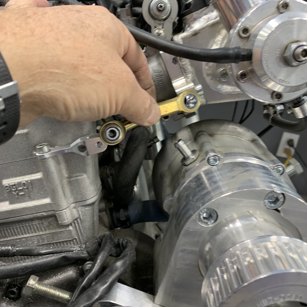
The other side has no bolts. The only thing remotely in line with the intake is a breather vent in the side of the head. It'll make a fine mount - ever try to remove one? They're in tightly.
So I made this little slide over, indexing mount. Slide the piece in place, turn about 20 degrees and it's locked in place.


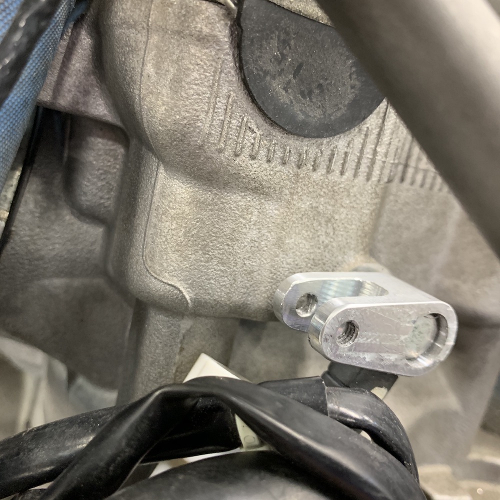
Got two of my heims today - the pair with through holes. The other pair has studs and will thread in where I've threaded in with a bolt.
Made the tie rods for the heims and did a quick install check. All fits perfectly.
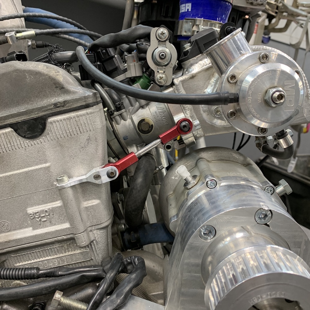
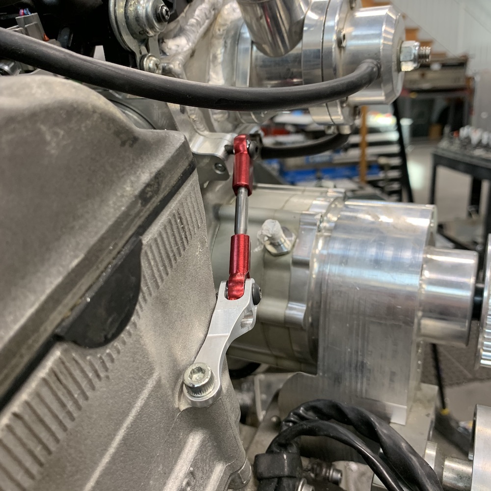
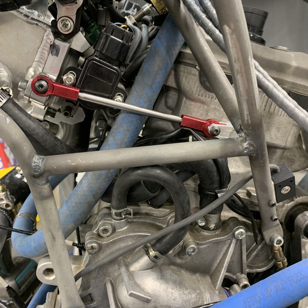
Just gotta wait on the studded heims and this part's done.
This concludes the building that happened up through the end of 2019. Click on the link below to be taken to what happens in 2020.