The Mini-Raptor Build 2017
|
2016 build 2017 build 2018 build 2019 build 2020 build 2021 build 2022 build 2023 build 2024 build 2025 build |
 |
 |
 |
 |
Jan 7, 2017
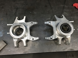
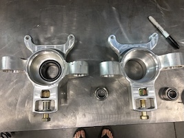
Right front upright is finished (mechanically - still needs a little detail work).
I had to redo the mount for the caliper so that it uses the OEM style plate to hold the caliper in place. I'm using the plates that came with the big rotors instead of the OEM Polaris plate - it fit better and mounted in an area that has more meat. To make the plate fit I had to machine .250 off the face of the mounting arms on the side closest to the rotor:
Rotor side view - caliper mount is upside down in this shot and the one above. Mounting points and position are symmetrical and I was more concerned with bolt hole alignment when I snapped the pic.
Hub, caliper and mount all in place (correctly):
I had to open up the area where the CV boot and CV enter the back side of the carrier for clearance. You can see the difference in wall thickness between the picture above and the one below.
I also got the bushings for the lower a-arm inner pivots done:
Flyerrider picked up the a-arms, front bulk head and jig from the laser place earlier this week. I'm still waiting for pix. He has a buddy that works at Space-X that's going to do the welding - so we can all be jealous of the work that will be done.
I've boxed up the lower front clip and all the spacers and such that are needed and sent them to Flyer. They'll be putting the arms and bulkhead together.
I plan on getting the left carrier done this week and hopefully heading to Kommiefornia the end of this coming week with parts in hand. I should come home with a finished front clip.
Jan 8, 2017
So a bunch of people have asked how much time in making the spindle. First one? Guessing but probably close to 20 hours of standing in front of the mill. Slow and careful.Today I started on the left side.
I need to correct a comment from earlier - said it was a 54 lb block of aluminum. That was shipping weight. The piece was 49 lbs.
I decided to keep track of time spent on this one. Getting it cut down to 10x10.5x5 took a bit of time, as did cutting the pockets in the corners to hold it to the table. Last time I held it with tall clamps and then ended up cutting in pockets for clamping. I realized I didn't need the tall clamps, just the low ones. I gained all sorts of clearance for the tooling.
So start up this morning at 10:00 and exactly two hours later, the first machining cut was run. I ran until 3:05. So that's 5:05 down.
I got the bearing hole and retaining ring groove cut in, the outer face and the recess for the brake caliper bracket cut out and the upper mounting ear basically profiled.
Jan 9, 2017
6:25 worth of work today.
My brain hurts.
I forgot to weigh it before I stuck it back on the table.
Jan 11, 2017
Left spindle is finished - well... except for having to redrill the lower ear tabs. For some reason I ended up .1" off when drilled.I plugged, welded and will redrill tomorrow. I still have some corner and edge stuff to attend to. Spec wise they're the same - all the important pieces are where they're supposed to be. Cosmetically there are a couple differences - minor and probably not easy to find w/o knowing what to look for.
Final weight is 4 pounds w/o the bearing. It took 16:50 to make 46 pounds of chips.
Flyer's going to start pulling all the a-arm stuff out and assembling it in the next day or so. I'm waiting on pix...
Jan 13, 2017
Pictures started showing up on my phone last night:Solidworks pic of what this assembly looks like:
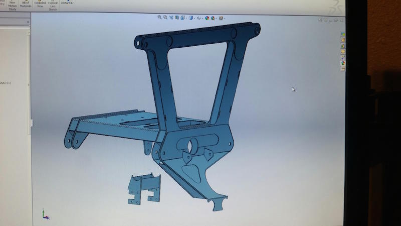
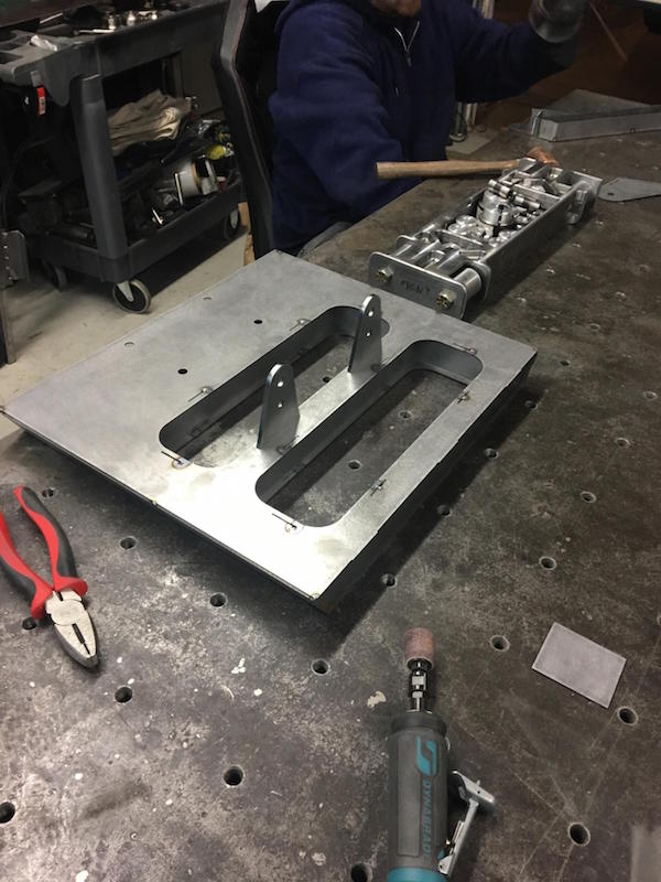
Here's the shock tower:
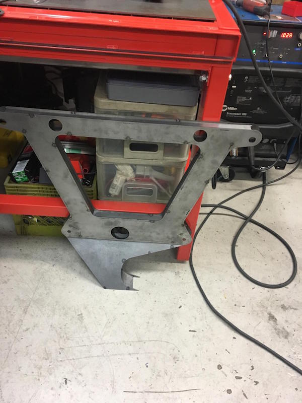
Pretty fancy break/roller work:
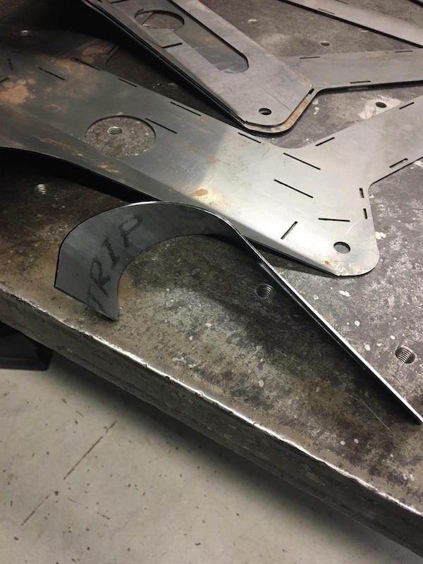
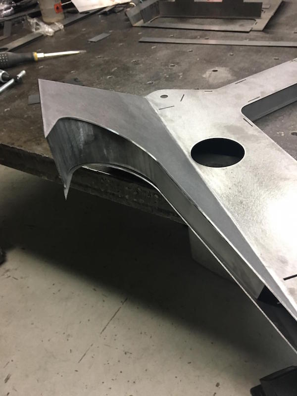
Assembly by BeJay:
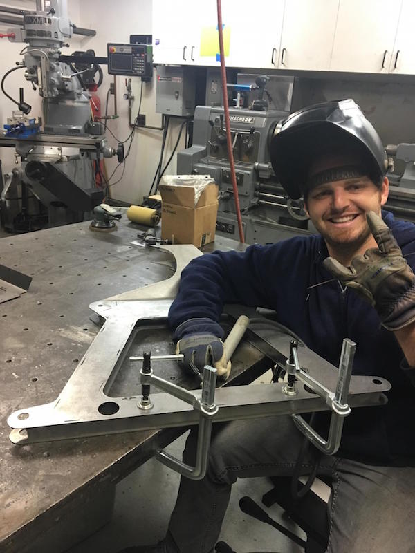
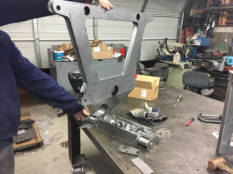
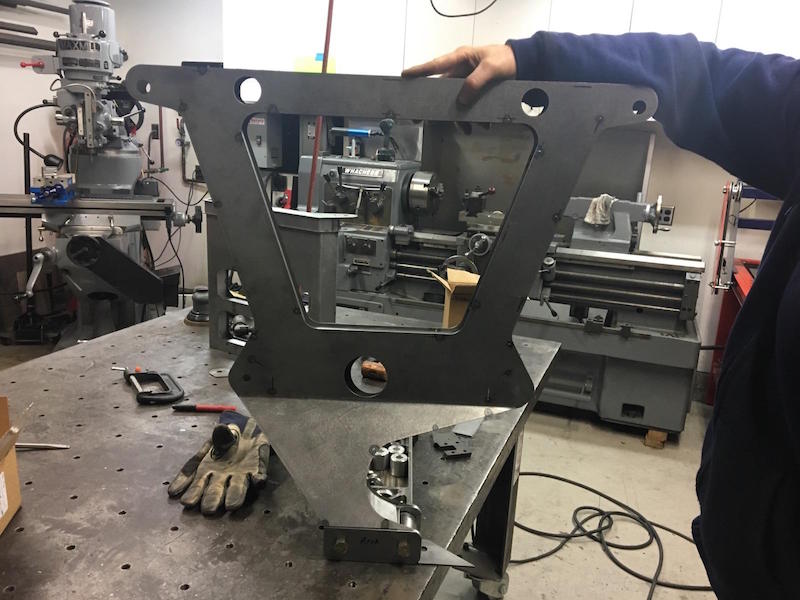
Upper a-arm bulkhead:
Jan 14, 2017
Got the spindles done today - all the hardware fits except for one pair of hi-miss spacers that I screwed up. Gotta place another order...
I couldn't resist and had to put it together:
Full lock left:
Full lock right:
Installed in the wheel:
Full Bump?
Jan 17, 2017
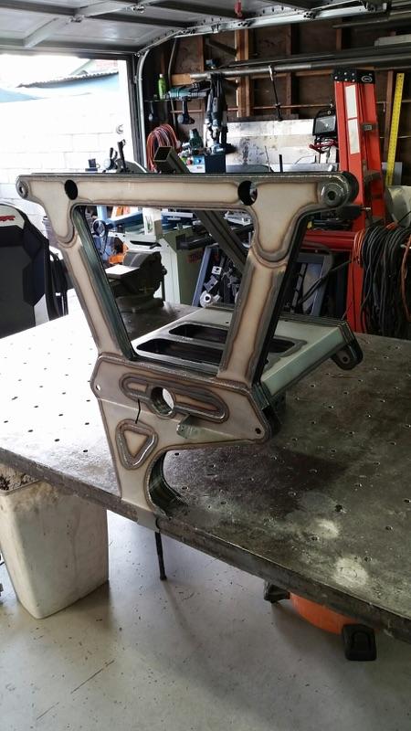
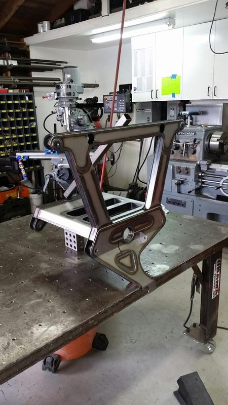
Bulkhead Porn:
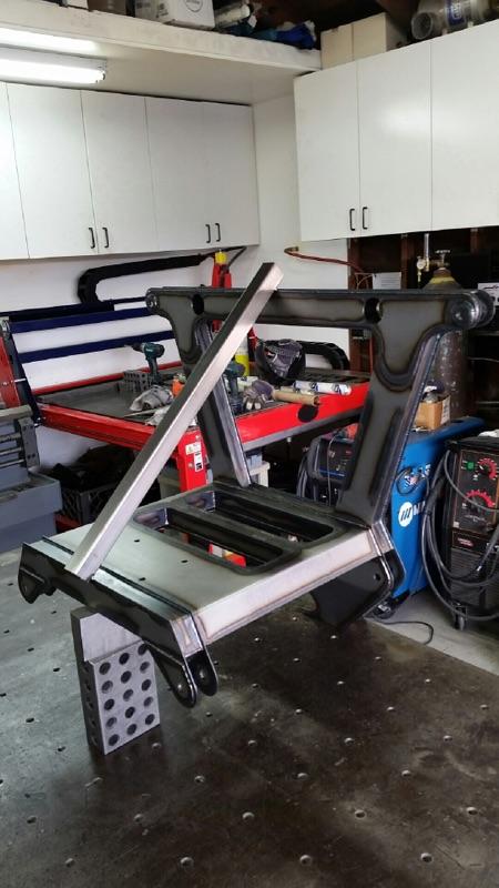
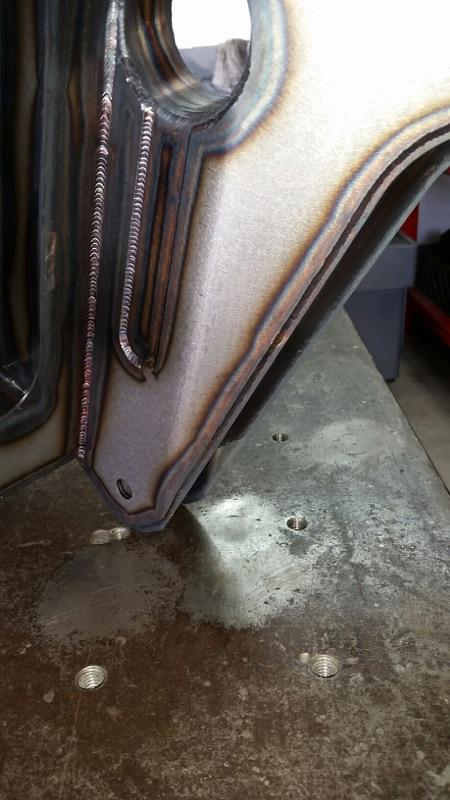
Jan 21, 2017
Lower arms are coming to life:Innerds:

Lower shock mount detailing:
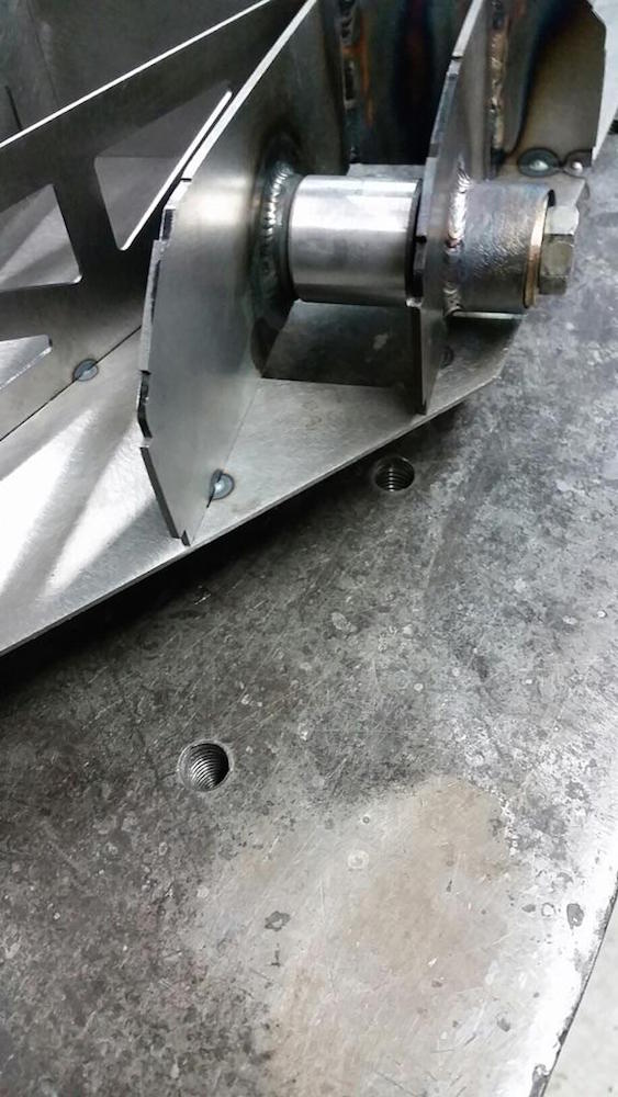
Lower shock bolt nut pocket:
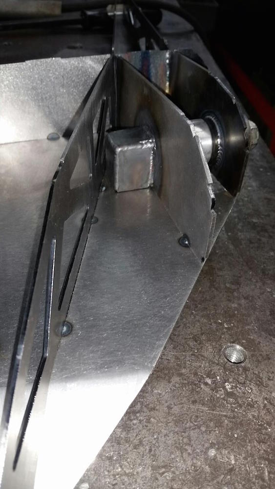
Bottom of shock mount and nut pocket:

Mirror twins:
I'm glad to see the arm fits the lower bulkhead:
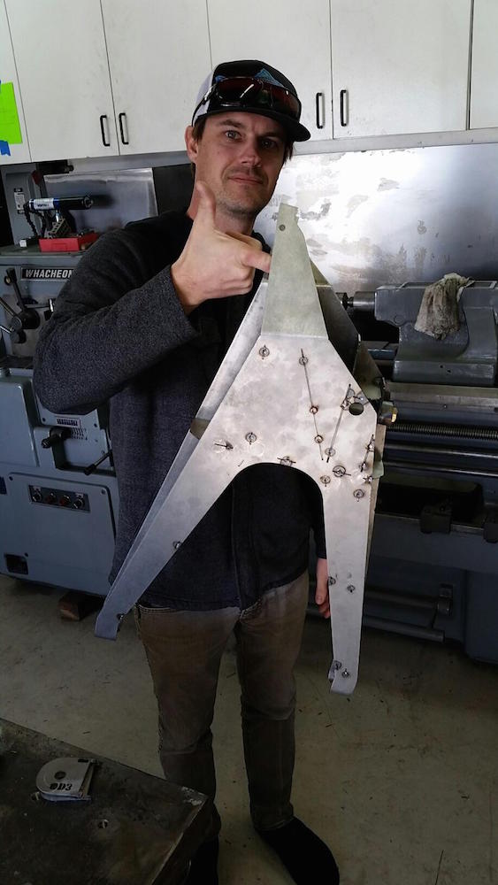
Action Hero Flyerrider himself modeling a "so freaking light" a-arm:
Upper bulkhead, meet lower bulkhead:
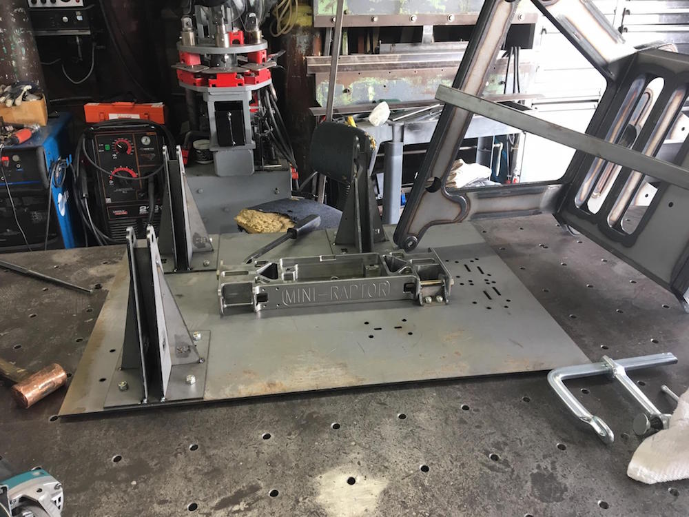
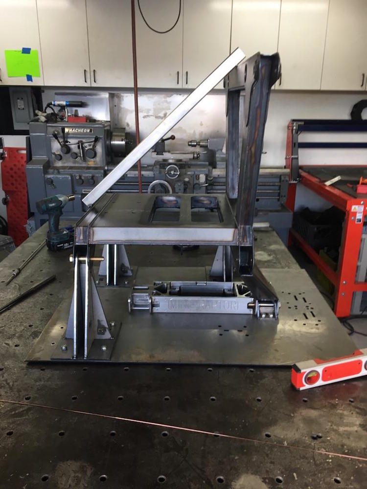


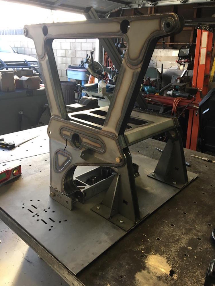
Arms in place:

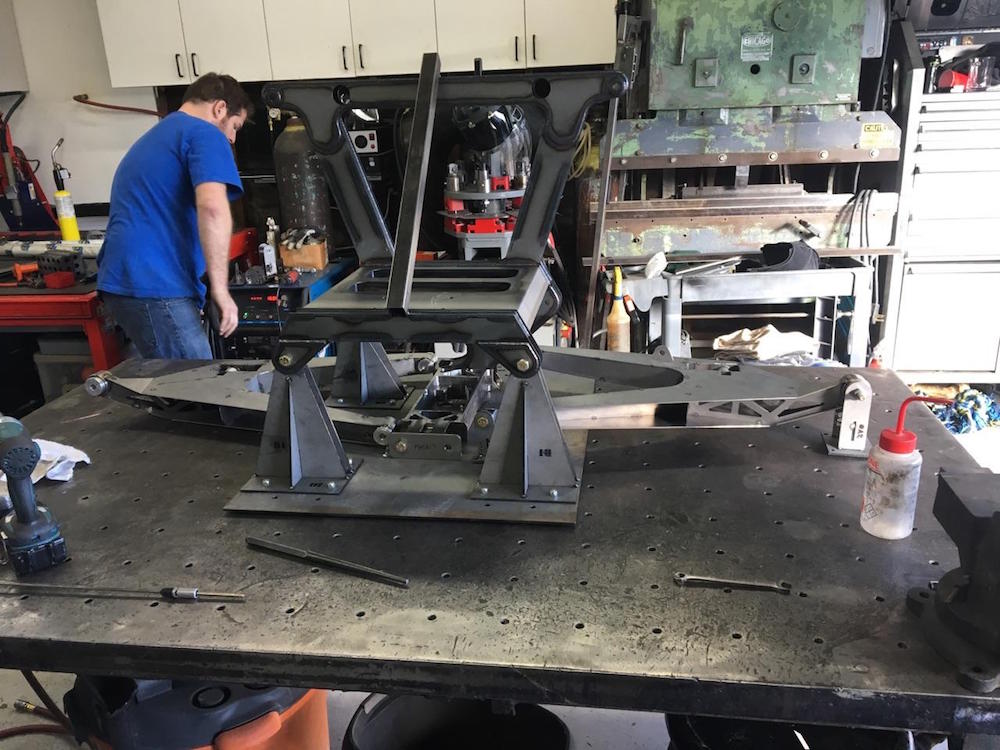
Flyer says that these things are about 10" longer than the lower fronts of a 1000XP.
Feb 9, 2017
Here's the spreader support. It has linear bearings in the ends and will be welded into the lower part of the bulkhead:
Tie rod - the bungs will get machined to a hex so I can get a wrench on them:
Feb 17, 2017
Xbird
"Rather than fooling around setting up a hex, two flats on one bung and it's good to go."
Me
True, but these are more fun:
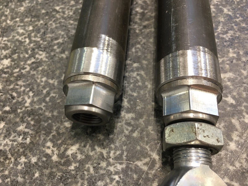
Ready for welding:

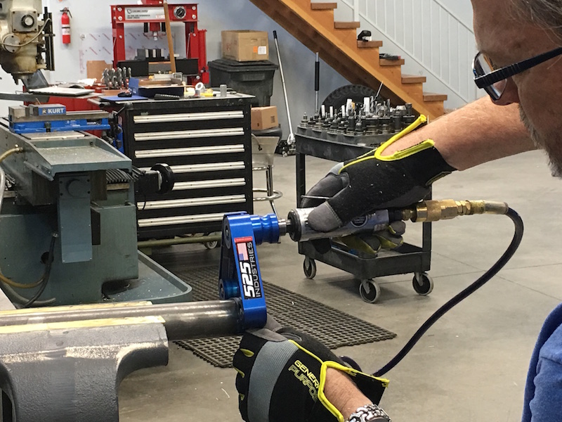
Tube preparation done with 525 Industries 360 Tubing Grinder.
Soon to be available at your local - well... I don't know that yet, but get one when they are available.
Contact bullnerd here on the site for more info. It's a bad ass little unit.
April 12, 2017
More in a bit.
April 13, 2017
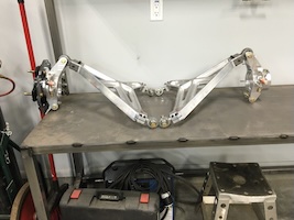
Front clip attached to the build table. Does this qualify as a Trophy Table or a Long Travel Table?
It's set at a 5 degree rake as opposed to the 6 I started out with 'cause flyer said so - then JD66 comes back and says "No, it's 5". Crap.
Cut, grunt, push, reweld, tada.
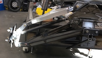
Lower arm fitment:
Shock attached:
Upper arm and spindle and tie rod in place:
Steering assembly:
There's a winch that gets stuffed up under the lower bulkhead too. Oh fun!
Axle and wheel onboard now:
Time for bodywork fitment - The arches were designed for a smaller diameter tire. Benihana has offered to redo the fender flares - need to send him a few pix and text messages to see just how he wants to go about getting this done.
Full bump and clearance issues:
Passenger's point of view:
Full droop:
Today I need to (put together the Cagewrx cage for the wife's XP 1000 four seater - but I'm not gonna) finish up a support system for the bodywork.
The system I set up on the passenger side allows me to adjust both width mounting and vertical mounting of the side panel (man I love Cleco clips!). I'll copy it over to the driver's side next. I need to put the roof on to get the body side panels in the correct vertical orientation and then continue on hood placement.
IT LIVES!!!!
Apr 28, 2017
We finally had a few days between guests and I ran to the shop!
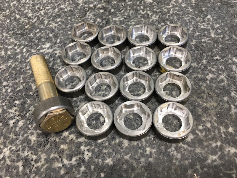
Spent the first part of the day cleaning up and making a few needed items - nut pockets. I love these things! Most of this build will only take one wrench per fastener - I'll capture as many nuts or bolts as I can get away with. It makes working on things SO much easier.
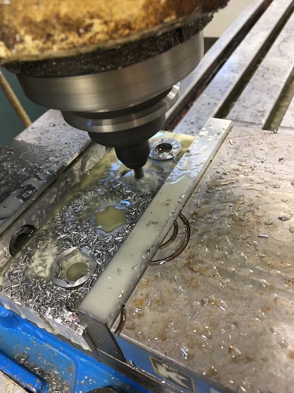
Nuuuuuuuuut Pockets:
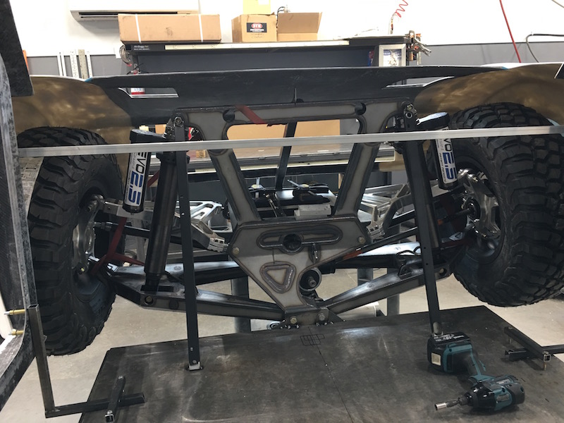
I realized I didn't have the front end attached to the build table quite well enough so I went about remounting and bracing it a couple of days ago. The stays from the top of the shock tower down to the table made the biggest difference.
I also went ahead and put the cab together and braced it so it moves as one solid piece instead of fighting with three pieces that didn't want to stay together with clamps.
This made getting the body and hood up in place with the suspension at full bump easier - I made some table clamps that allow me to move everything around - you can see the front two in the picture above.
This is with the body sitting 6" off of the table - too much...
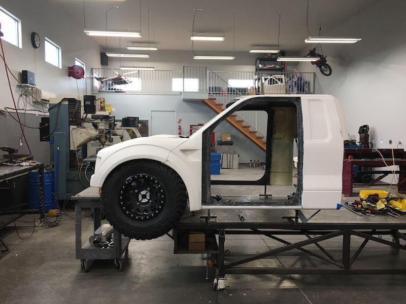
There's just a little bit of rub right now on the fender's little rolled in lip:

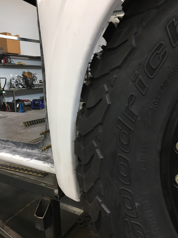
I trimmed the lip back about 3/8" and the wheel turns w/o hitting anything.
I think I'll start dropping the body in 1/2" increments and trimming the fender flares back. I'm hoping to drop the body at least two if not three inches - there's actually more room under the hood than I expected. (can see this in the picture with the bracing).
Once I get that done I'll start working on the frame that will hold the radiator and front bumper.
Unfortunately I tweaked my back fairly badly on Wednesday fighting one of the wheels off the spindle so I've sat out the past two days.
I hope I'm back in the shop tomorrow.
Apr 30, 2017
Worked on getting the body fit better. I started out trimming about half the vertical part off the flare:
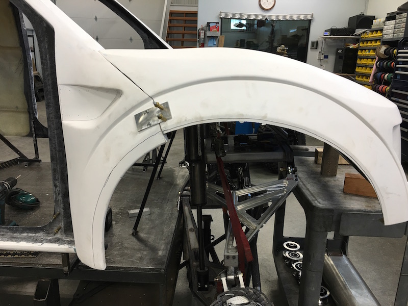
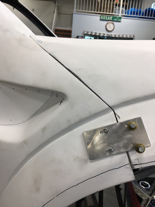
Then I ended up trimming all of the vertical part off and have clearance.
Full bump:

Ride height:
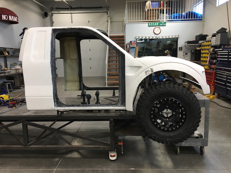
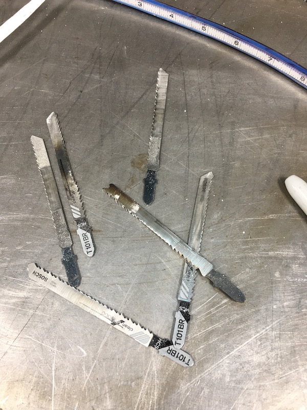
I have to laugh - wood blades don't work last long cutting fiberglass.
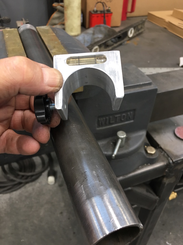
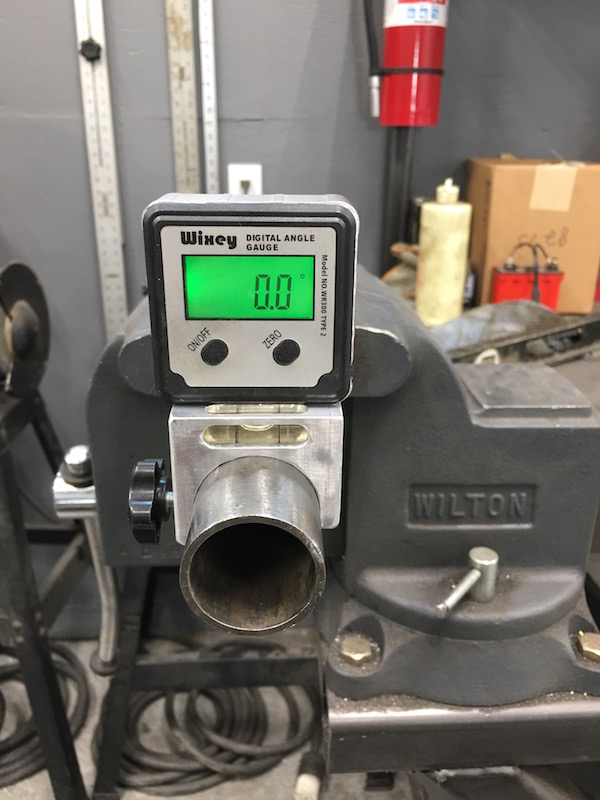
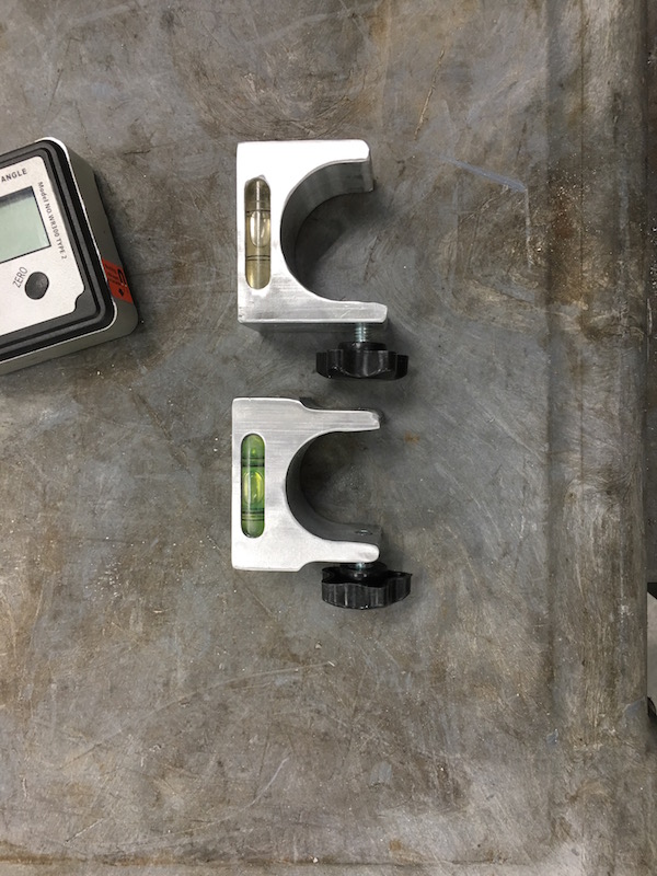
Been wanting to make these for a while - they'll help me keep the tubing oriented when I'm bending.
I still need to make the 1":
Jul 13, 2017
New bulkhead arrived last week but I've been busy with other stuff.
Doing my research on rear anti-squat so I can start the rear end work - gonna make a mock up of the rear that I can move all the points around. Once that's decided it'll be build away.
Have had so many other projects recently it's been back burnered. Eh, it's only a five year build...
July 18, 2017
So on Saturday I tack the last front bulkhead in place and then start working on how I'm going to fit the front tubes together.
Off to the rack that my stuff's kept on. No 1.5" tubing in my collection. WTF? I thought I had some. Got quite a bit of 1.25x.095, but no 1.5. I have about 6 feet of .065 mild and that's not gonna work.
Can't do anything until Monday. Monday arrives, I make a call to Advanced Metals here in northern Phx "Hey Pat, I need five sticks of 1.5x.095 chromoly." Before I can finish he tells me "Nope, don't have any and aren't expecting until August 31st." WHAT???
He said he'd call me back later that day. Still waiting. Arrrggghhhh.
Waiting on a rear five link carrier to show up at my door step now. Bullnerd's sending me one of the Briggs carriers so I can use it as my model and upsize the geometry to fit the Mini-Raptor.
Stuff is actually starting to happen on it again - been a bit long, eh? The other projects are finally getting all tied up - still have to skin the green house but it's been too darned hot to work outside.
plkracer
I thought you were doing a 4 link?
If I were to have another go, I would head that route, seems like the single arm to the rear is pretty strong, and there is no need to worry about caster angles.
Me
If I can't get the five link setup to work (there may be a clearance issue under the clutches) I may copy what they're doing on the X3. It's a pretty trick setup.
Started making calls about tubing. Seems that 4130 in 1.5x095 is non-existent. I got a long windy story about why, won't bore everyone - totally politics. Argh....
So I now have five sticks of 1.5x095 DOM. It's not a race truck... I have a bunch of 1.25 and 1" 4130 that'll get used for bracing.
Got the new bulkhead tacked in place:
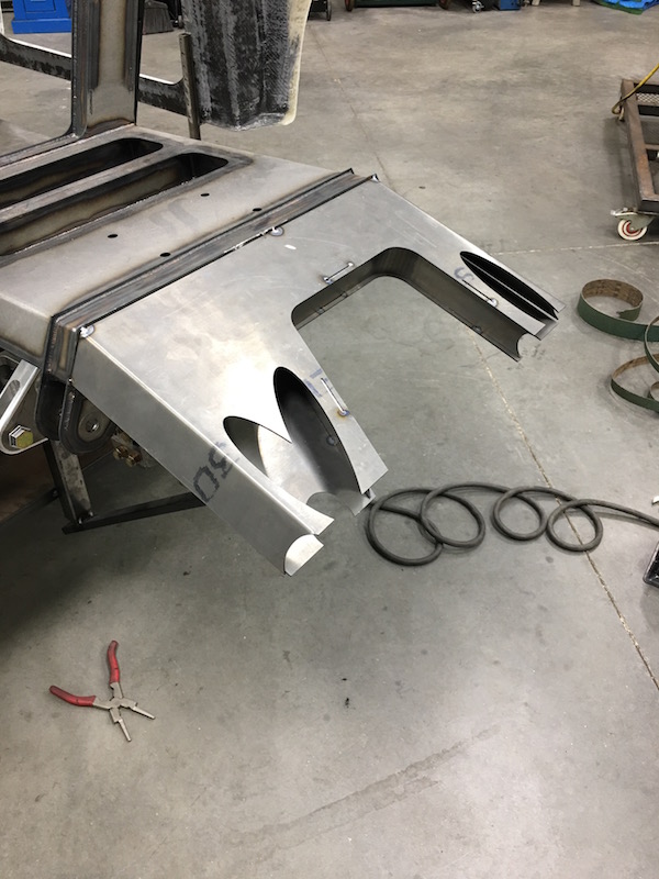
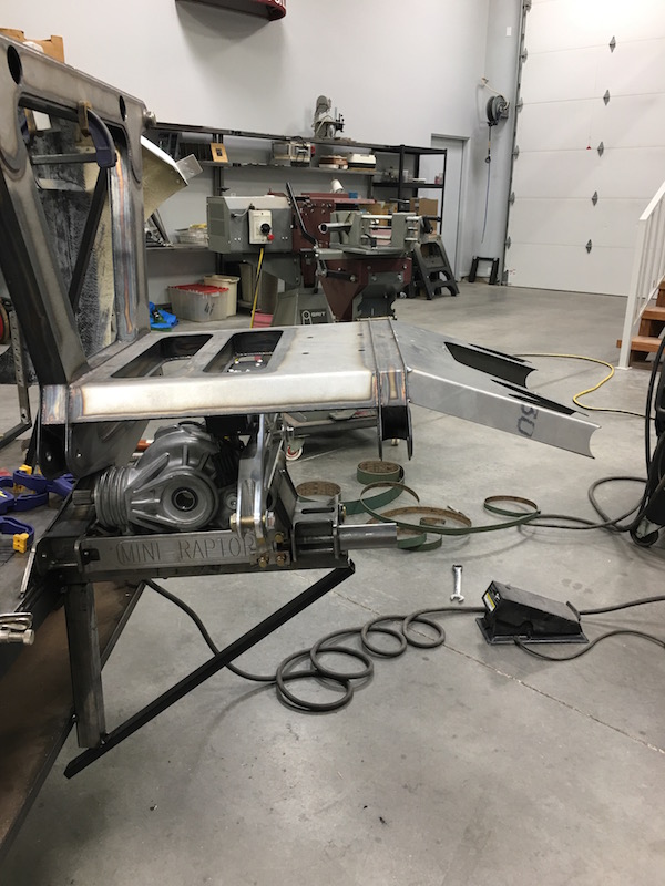
Started fitting the lower support tubes. First cut washers that will hold the bottom tubes and get TIG'd to the front of the lower bulkhead.
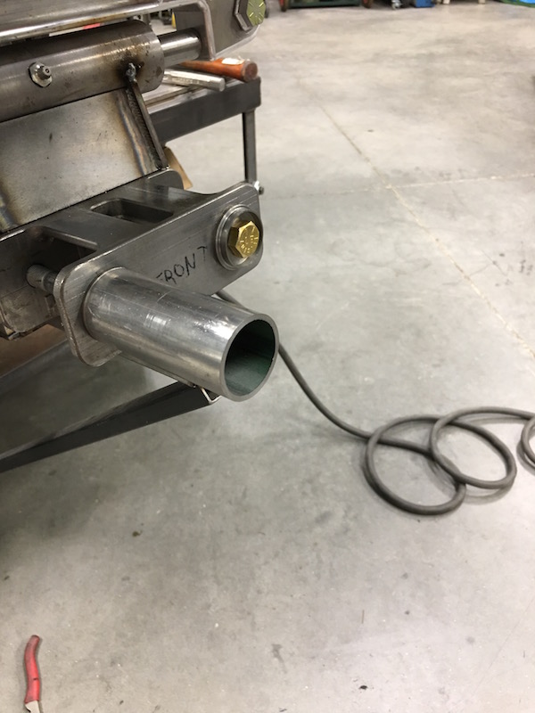
Then started coping the tube that goes up to the bulkhead:
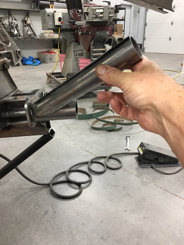
Walked over to the coping sander, put the test tube in for angle fitment, started it up, pulled the lever that pulls the tubing into the sanding belt and all hell broke loose.
It just spit out this 1" wide piece suddenly and I let up on the lever thinking "WTF?" Looked at what ever went flying by and then realized what it was.
Pulled on the lever again, spit another 1" wide piece out! I made the last 3" last another 10 minutes.

Okay, it's an OLD belt that was about 90% done and was already missing about an inch of width - it was time. Gotta call ATV Racing and see if they have any spares. Making McMaster order right now…
Jul 19, 2017
And to day I have most of a front clip. I still need to do the one diagonal between the two upper main rails.
Lowers in place:

Upper main rails fitted to the lowers:
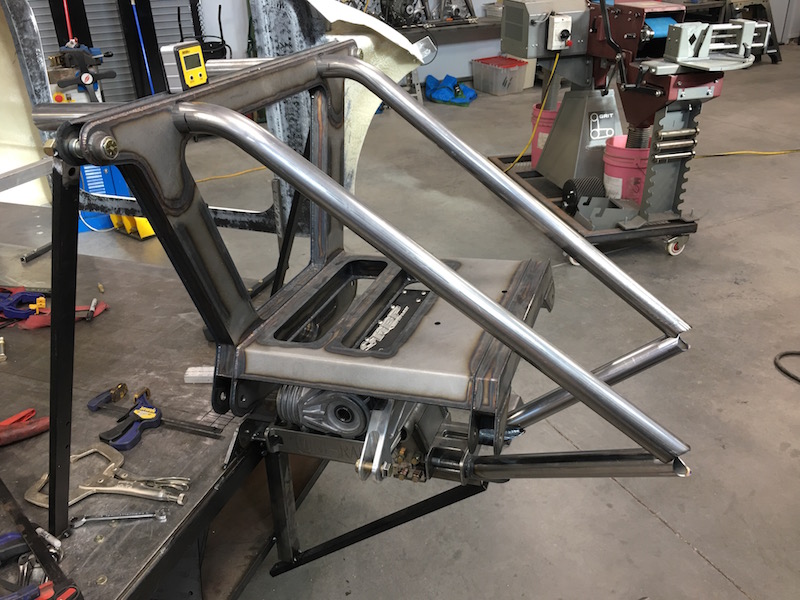
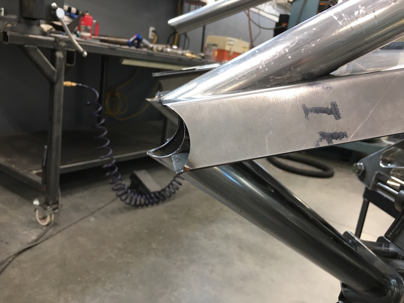
The bumper tube clips in place - I have to say I was impressed that I got it this tight. This piece is just a tube, not the bumper. That's a little later.
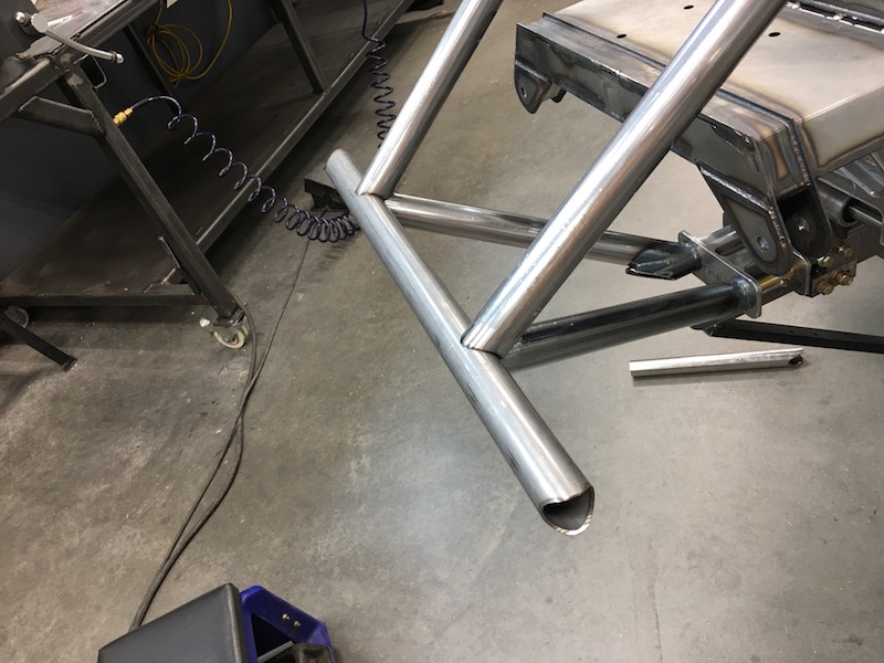
The front bulkhead - this thing got put on and off and on and off and on and off and...
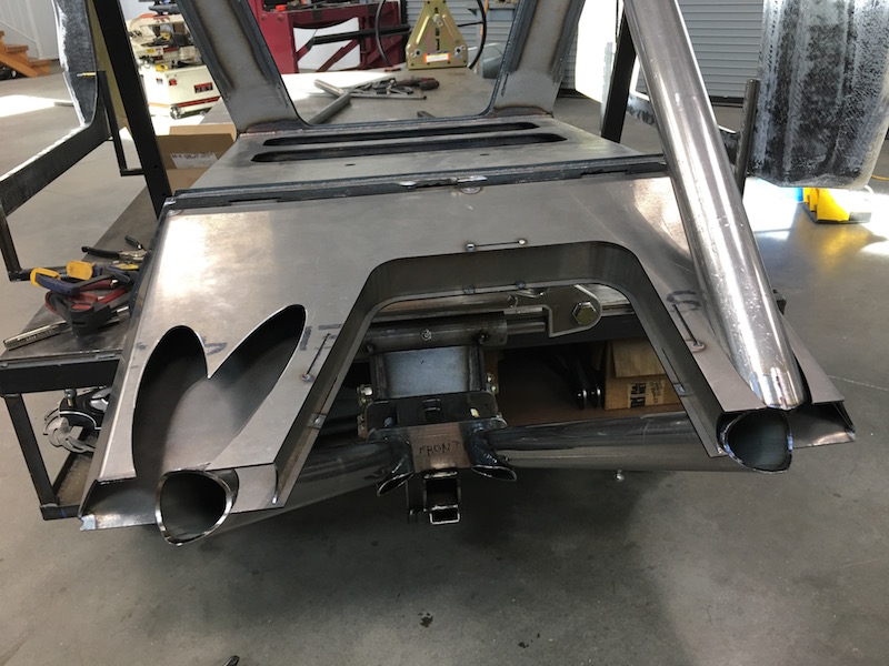
Front bumper coping work:
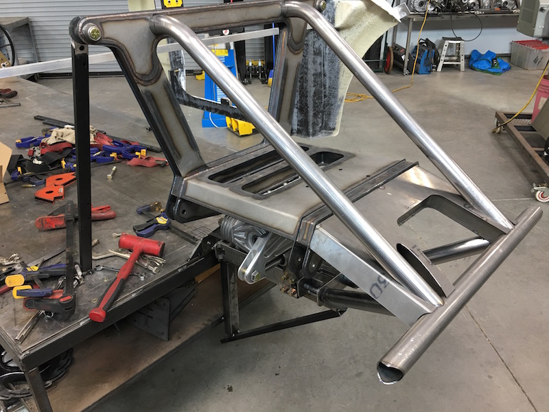
Everything other than the cross brace in place:

Jul 20, 2017
bdkw1
Nice!
Me
Coming from you I say "Oh thank you Master!" (:
Now I have to figure out all the tubing that gets put behind the structure.
JD66
Awesome! Glad to see it went together well, those pictures have been a long time in the making!
Me
Indeed! - and I think I figured out how to weld the tubing together then put the plates on the tubes - the uppers slip through the bulkhead holes and the lowers aren't welded in place yet, just held in with bolts. I can weld the tubes together, slide the plate work in place, then tack the whole assembly in place. Issues we were worried about are a non-issue now.
Bullnerd
Excuse me, do you sell plans for that sweet front end?
Who ever designed it must be one cool cat!
Me
Talk to JD66 and flyerrider... I'm just sticking the stuff together.
Jul 25, 2017
The tube from Hell:
It fits against three tubes in the front of the bulkhead, it lays into a cut notch in the bulkhead plate and it intersects at the top in the middle of the bend.
It kicked my ass. Three hours. I didn't have to do it twice. (which I can't necessarily say about one of the front upper tubes)
I got the front three copes done fairly quickly then started looking at the blending, bending cope.
Three short scrap test fit pieces later I'll admit - it beat me. I finally cut the cross tube short about 4" and then took a bunch of tiny rods (out of the too large tube blending measurement thingy that I have) and zip tied them to the end of the now shortened tube. I slid the little pins up against the tube it's where the two are supposed to meet and it gave me a shape. I took the four inch piece I cut off, slipped it back into place inside the pins and then drew the line that the pins showed me then started cutting/grinding. It fit like a glove.
Put the two pieces in the lathe, square up ends, bevel edge for welding. TIG together, put back in lathe, do a little magic and nobody knows it's not one piece - especially after powder.
Reinsert and it almost clips in:
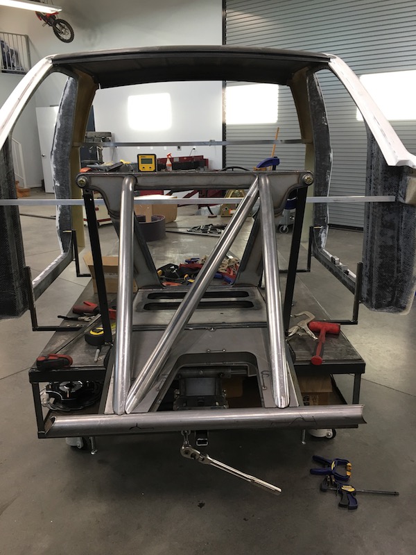
Drop grinder
Walk away
---------------------------
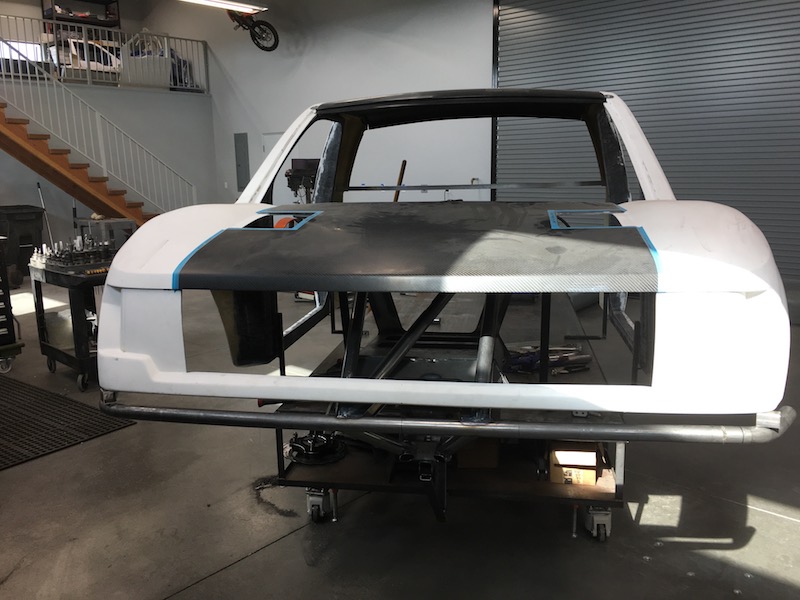
Today I finished up the front clip.
I kinda like my HF tube roller. I was able to make the front bumper follow the body line perfectly. And only needed one tube to do it too (no welding).
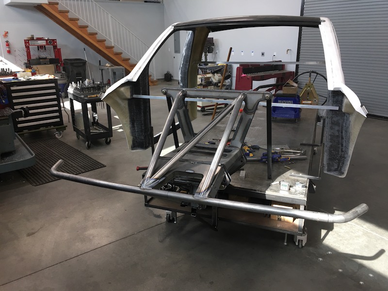
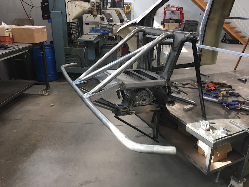
I've TIGed about 35% of it together and will finish weld later - think I'll probably make a chassis holder that I can spin down the axis of the car so I can do the rest of the welding - my TIG work is getting better all the time (still pooling a tad... - welder setup needs to be played with).
This is with the body resting 1.25" above the front bumper - there's a little bit of inner lip clearance issue between the up tubes and the back of the front clip. If I drop it another .5" I'll have to trim the edge for clearance. We'll see.
Gonna mill some trick tilting mounts for the front - it'll pin in back and it will tilt forward like a Corvette. After that I'll start on radiator mounts.
Jul 26, 2017
Work break
And now back to our regularly scheduled programming
Jul 26, 2017
Radiator is in place, not installed, though.
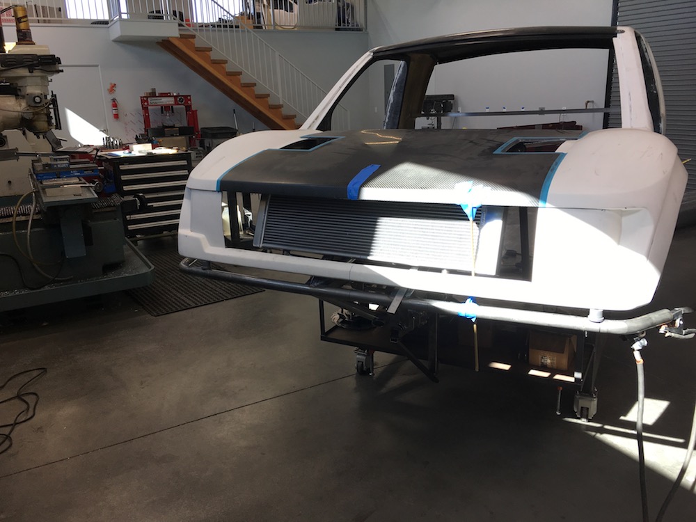
It's really tight:
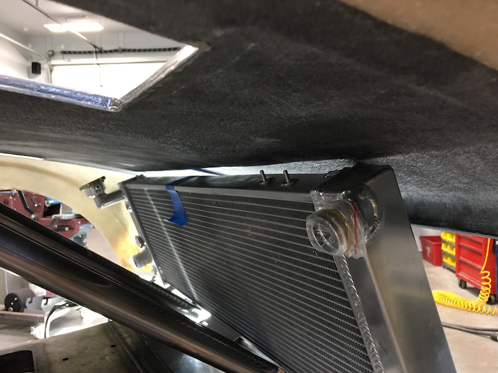
There's about a quarter inch of clearance both down at the bottom front where the grill will go in and then on the top below the body.
I'm doing stand offs from the front down tubes. They're short so they'll support the radiator really well.

I only have the passenger's side one tacked in place and will get the other one done next week - got plans for the next few days that won't let me have shop time.
I still need to figure out where the fans are going to mount and what the shroud's going to be like. I want to duct as much of the hot air out from under the hood and either up through the louvers or down out of the fenders. Louvers would be cool but not sure how efficient and do I want hot air coming over my windshield?
Not sure what's gonna happen up on the top mounts yet. Totally on the fly building right now.
Aug 4, 2017
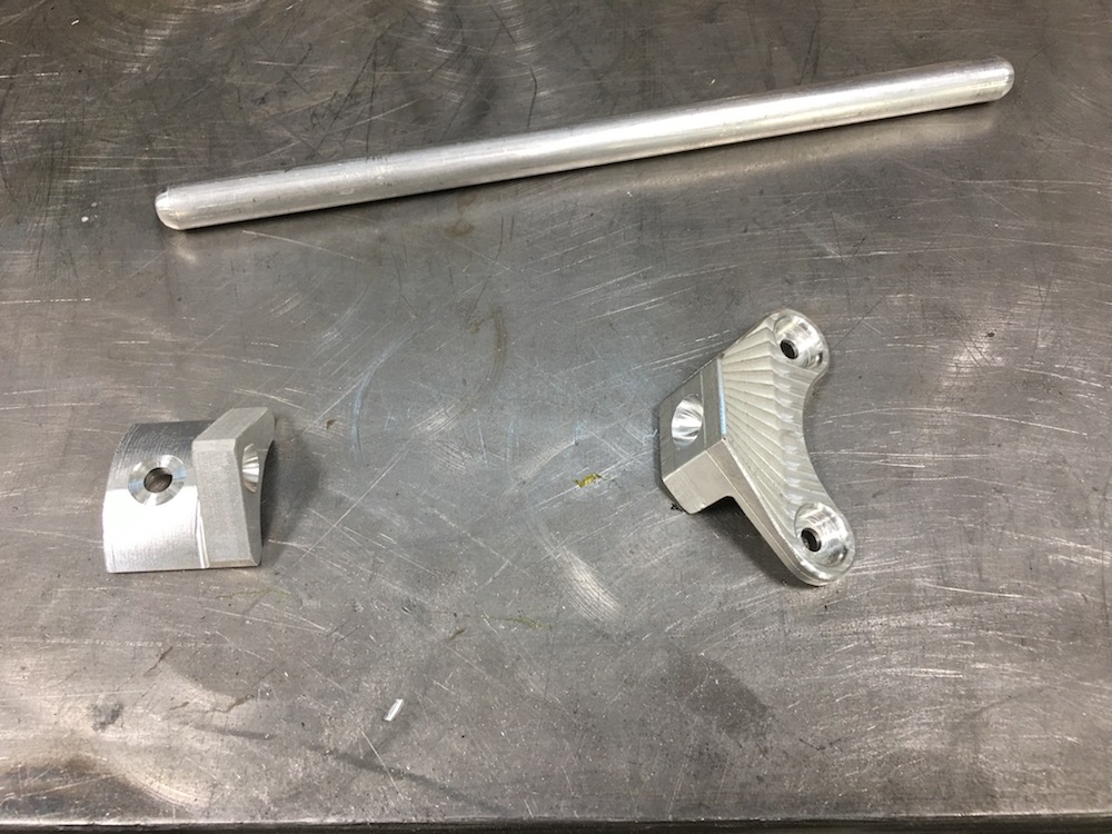
Lower mounts are in and today I'll work on the uppers. They'll be two billet pieces, each one attaching to the two studs on top of the rad and they'll be tied in with a couple of aluminum tubes that head on down to the frame tubes. I got a blind nut installation setup so I'll do a pair of them on the tubes and a billet piece that fits the tubes and receives the tube that runs between the top mounts and the tube mounts.
I'm impressed with how stiff the mount is already but it needs an upper to keep things in place.

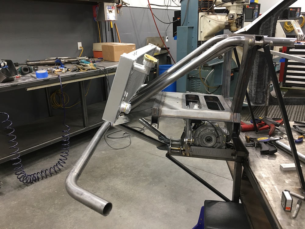
Ordered three Spal 7.5" fans and will start on the shroud once I get them.
The rad that flyerrider gave me (same one I have, but already trimmed up and with shroud and two Spal 9" fans) showed me that I wasn't going to be able to use the pair of larger units nor did his shroud allow for the clearance I need.
I need to make the inserts that will go in the four holes visible in the upper bulkhead and allow me to bolt in the winch (goes in the hole in front of the diff). Right now there's no support between the two plates in the bulkhead.
bdkw1
Stock mounts do not like off road beatings.

Aug 5, 2017
I'll take my chances for the time being.
Got the upper mounts machined now I need to assemble and install.
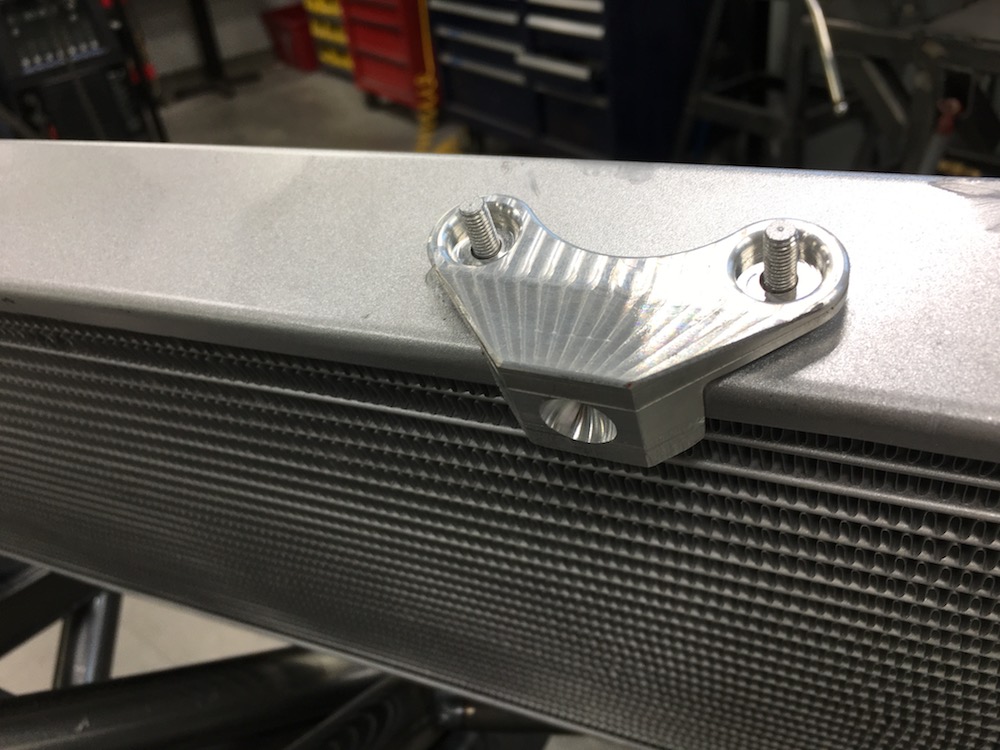
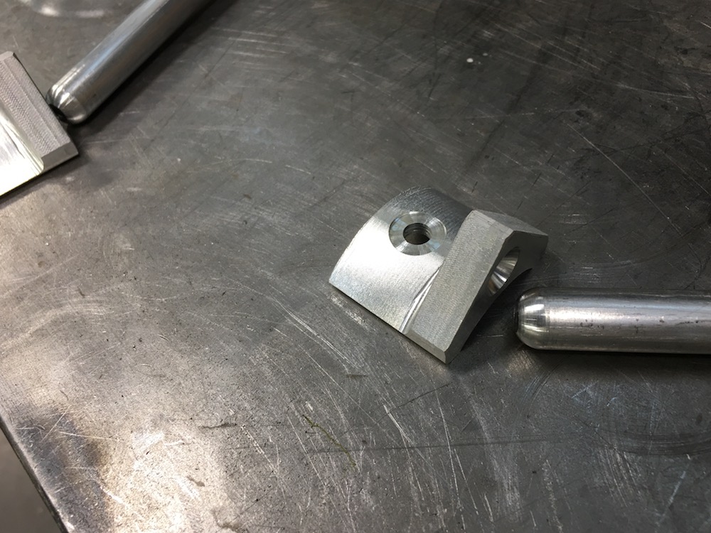
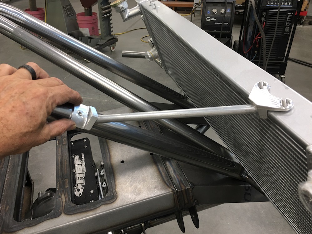
Nutsert installed:
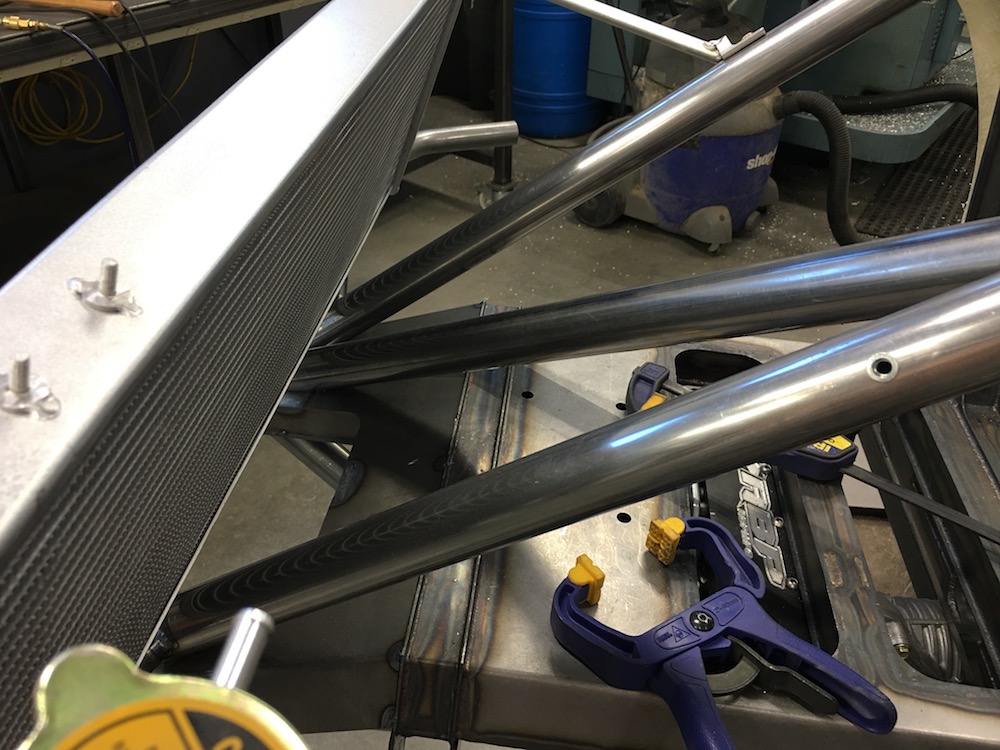
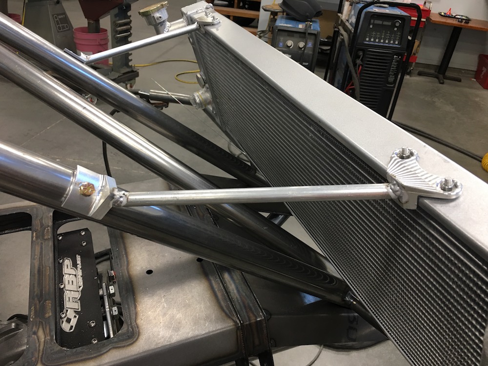
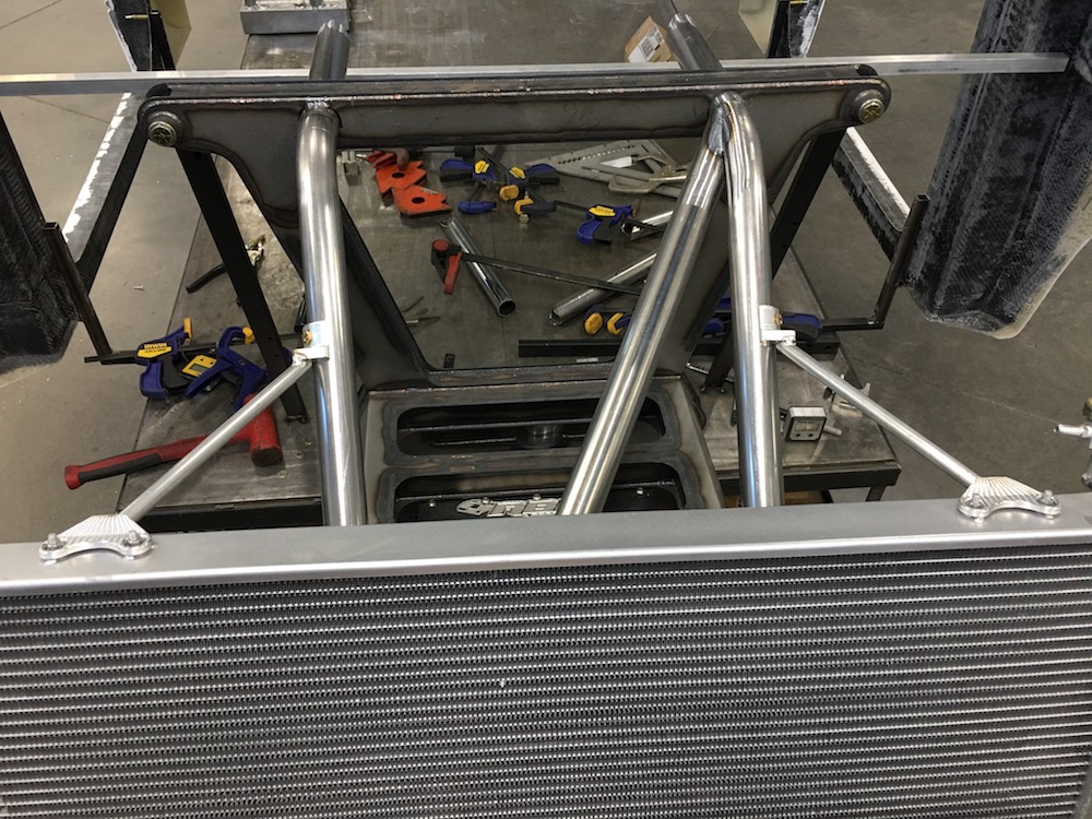
I'm gonna pack up all my aluminum bits that need welding and send them to B&B Off Road Engineering (TALON's place). My welding sucks.
I need to go find some .065 aluminum sheeting for the shroud next. The fans should be here early next week so I can get started on that.
Aug 23, 2017
Stuff is on order:
Vacuum pump for doing the vacuum bagging of carbon fiber, fiberglass stuff
Hot wire for foam cutting (guitar strings don't do well - went through a bunch of them when I did the RZR dash)
Loctite 608 Hysol bonding stuff so I can bond composites to aluminum and myself and the bench and what ever else it gets on.
Gotta stop by Loathes and pick up some decking (green house oriented - too many side projects. Hell... the Mini-Raptor's the side project anymore!) and some stuff to make a quick and easy heat controller for the wire cutter. Found some plans online that show how to make a very effective yet stupidly simple and inexpensive setup.
I'll be making foam plug that fits on the back of the radiator, then an aluminum frame for the radiator's cooling fans will be laid up over that and then I'll do carbon layers on both sides of the frame. Should be pretty trick when it's all done.
Slow progress - I have nothing but time fortunately.
Aug 23, 2017
Wheels
Hey k... any reason you mounted the radiator with holes in the tubing vs. Tabs that you can mount to?
Me
On the top mounts?
Not really - just sort of the way I visualized it.
Stood there looking at the top of the radiator under the hood thinking "How do I hold this" and that's what popped out.
Now that you make me think about it (thanks... ) I'm realizing that there's not a lot of load bearing mounting for the upper as far as shaking up and down. It's just fine fore/aft, but up down?
Hmmm....
Rad shroud may have just developed a secondary purpose of securing the radiator from bouncing out of it's lower mounts (which nobody likes how I did anyhow...)
Gee...
I don't like you guys now...
I'm going home.
LOL!!!
Pins through the bottom bungs. Yeah, pins. They'll hold it in
.Aug 29, 2017
Got a phone call a couple of days ago from Benihana!
He's been busy.
He asked me if I'd gotten anywhere with the vacuum molding of the headlight and tail light lenses - told him no. And then he asked if I was interested in some? Uh, YEAH!
I guess he wandered down the vacuum molding road like I did but got much farther. He's got it dialed in and is making them for his Raptor bodies and offered up a set to me.
This is gonna save me a bunch of time. THANK YOU BEN!
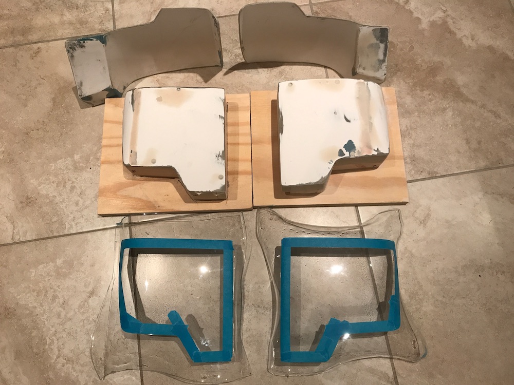
He said he was going to get online here and show some of the newer stuff he's been doing with/to the Mini-Raptor body. Teased me with a dashboard and some other stuff.
Guess we'll all just have to wait for him to share.
Nov 3, 2017
Been needing some inspiration and some direction for a while. The rear end has been a mystery for me - not sure what I was going to do. Four link? Three? Five? Coyote?
I've been playing around with ACAD, trying to get a rear geometry that I liked, but after three days of moving the same stupid wheel up and down and in and out and working on minimizing scrub and, and, arrrrgghhh.... Kinda frustrated. Not a good place to be when stepping back into a project, eh?
Went to breakfast this morning and as we walked up to the place a guy in a Canned Ham X3 is pulling into the parking lot in front of the place.
I stopped and looked at the rear end - then realized it's a guy I know that's been telling me I need to go drive his car. We followed him home and I brought it back to my place and then headed out.
So I drove a Canned Ham X3 Turbo this afternoon and I got to do it alone, in anger - yeah, it's been a while since I've driven in anger. - the owner has the same attitude - drive it as hard as you can, drive it as smart as you can, pay for anything you may happen to break. Didn't cost me anything other than a tank of fuel and I washed it.
WOOF!!! Damn, talk about impressive! Took it out to my favorite stomping grounds and put the fun pedal to the floor. The thing soaked up everything - I even started trying getting it out of rhythm through a few sets of whoops to see how it did when it got upset - couldn't get it upset. The suspension is incredible.
I can pick on a couple of things; it pushes (more so in the deeper sandy stuff) and it's hard to get the back end to start swinging out and even though it's the turbo, it's soft when you step on the pedal - takes it a minute to get wound up and start ripping. Keep it in the power and it hauls ass. Owner said that the present tires (Kenda Klever M/T) brought the push in pretty badly. I can see why. Other than that, I'd have to get really picky about stuff to complain. - loud, yeah, that is an issue and makes me all the more aware that the Mini-Raptor will be well insulated and muffled. Loud = Bad. My ears are old and touchy anymore.
I was more interested in what the back end was doing - pretty much soaking up EVERYTHING and never getting out of shape, stepping out, being strange. I'm just impressed.
I'm presently standing here at the computer with the X3 behind me and I'm getting ready to start taking measurements. I'm copying it - it works and works very, very well.
Pretty wild - my drawings over the past few days have been really close - but I was trying to keep too much scrub out. There's not much until the last 1/4 of the travel so it's fairly mundane in what it inputs into the chassis. I'm good with that.
Dropping the measurements straight onto the parameter drawing I have, I'll actually gain about 1/8" clearance from the wheel arches at ride from where I was designing. I keep thinking - just go get the stuff from Canned Ham and adapt. Would be SO easy! Nope, gonna make it. That's what this is all about.
The three link rear does what I thought it would - upper and lower to control camber and a middle one that controls toe of the wheel. It doesn't change at all. Keeps the wheel straight through the travel.
Part of the squishy rear feel of the XP is that the toe changes as the suspension cycles - toes in on compression and out on droop. Explains now why the rear end felt so planted and wants to stay right behind me.
Time to start putting pieces among all the points I've gathered.
"Oh Justin, how'd ya feel about doing a bit more sheet metal design?"
Nov 11, 2017
Rear carrier design done. Some of it will change when I machine it (back side detail wasn't drawn).
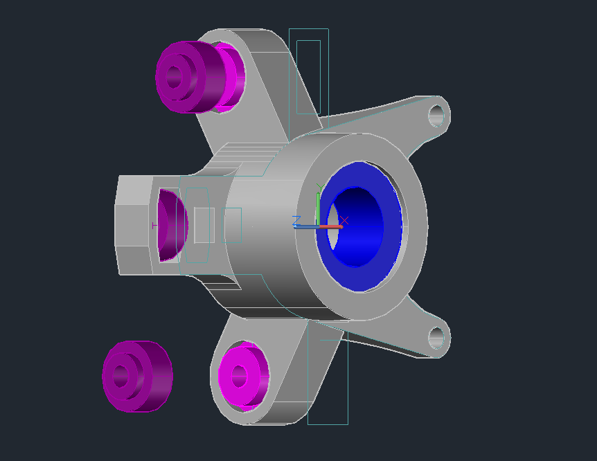
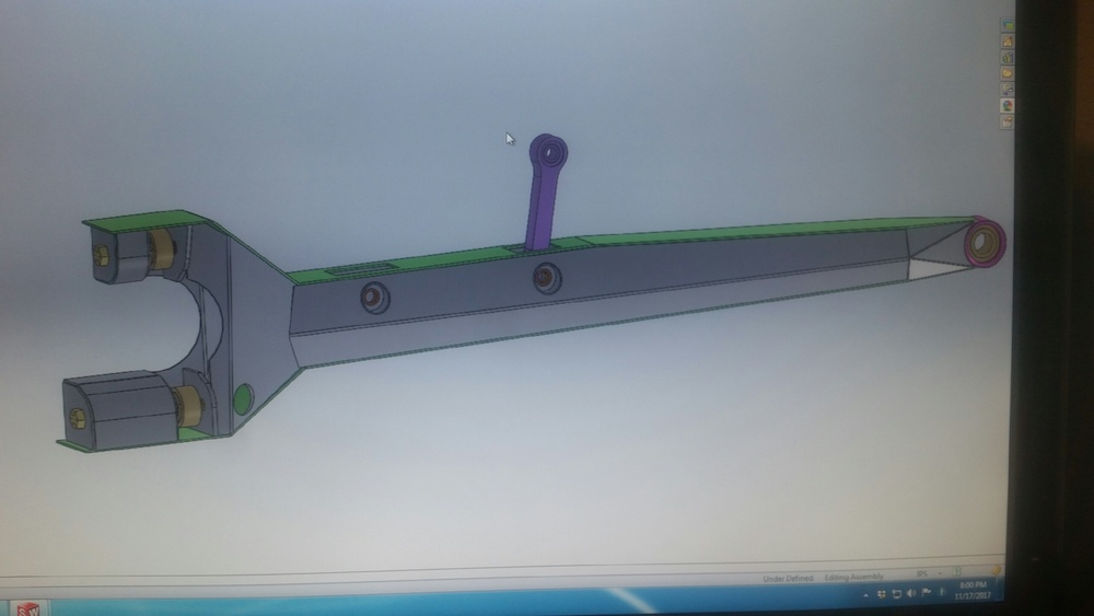
Trailing arm is being worked on.
Nov 14, 2017
Spent most of yesterday working on getting the trailing arm "dimension" designed and ready to send to JD66 - he's going to do the actual CAD to laser work for me and when it's all said and done I should end up with a box full of sheet metal.
Progress! Everything works so far.
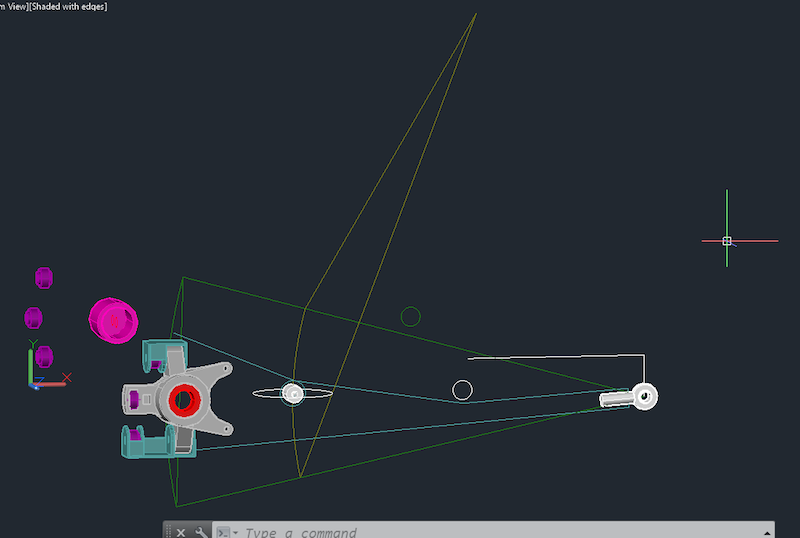
JD66 said he was able to import it too so things are looking good. Woo Hoo!
Still have to do the rear bulkhead/tranny mount.
Nov 18, 2017
There's a rear carrier hiding inside this 10" diameter, 5" tall chunk of aluminum.

I learned with the front carriers that holding the big chunk down can be a tad tricky. This time I got smart and set the piece up from the beginning so that it's held in place well, the hardware is out of the machining area and I'll be a able to work around it too. Both sides have the locating bars cut into them so that when I remove it to do the back side, it's just a quick flip and relocate X & Z - Y should be set.
I forgot to weigh this piece but I have another just like it (from a long ago project - two hubs that never made it into existence) so I'll weigh it before it gets machined on.
Time to let the chips fly.
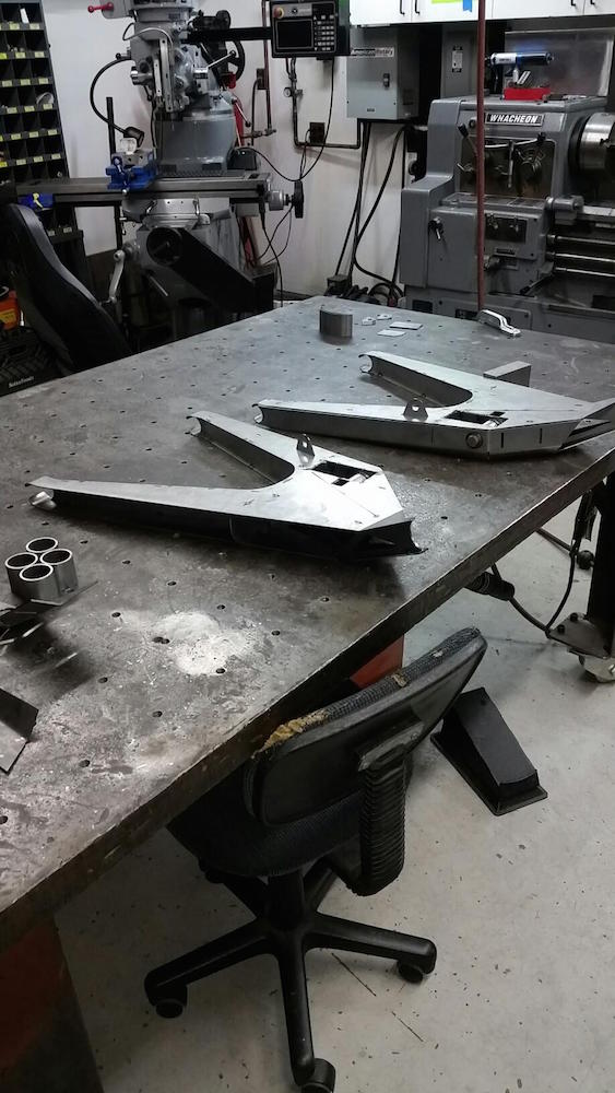
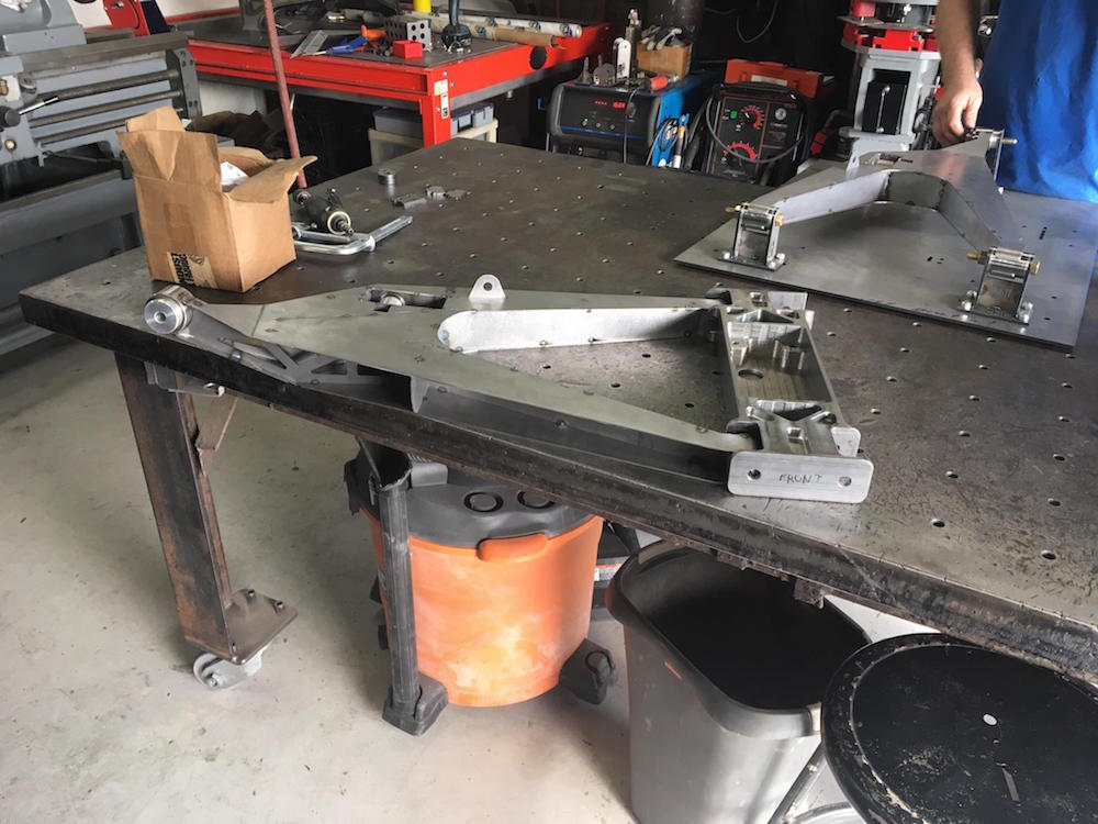
Here's the latest rendering of the trailing arm. There are still a couple small details that Justin's finishing up then it's off to laser/bender and then I have to talk Mr. Space-X into welding them up.
Nov 20, 2017

Nov 28, 2017
Arm renderings:
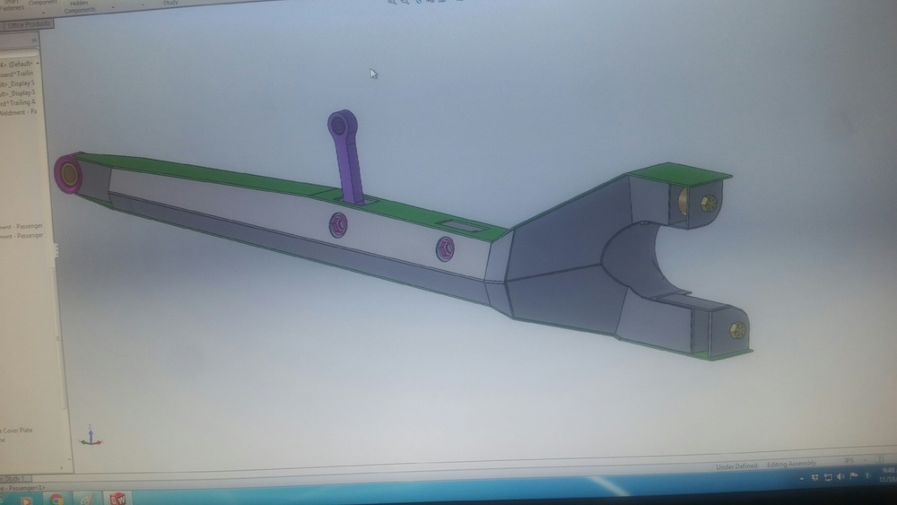
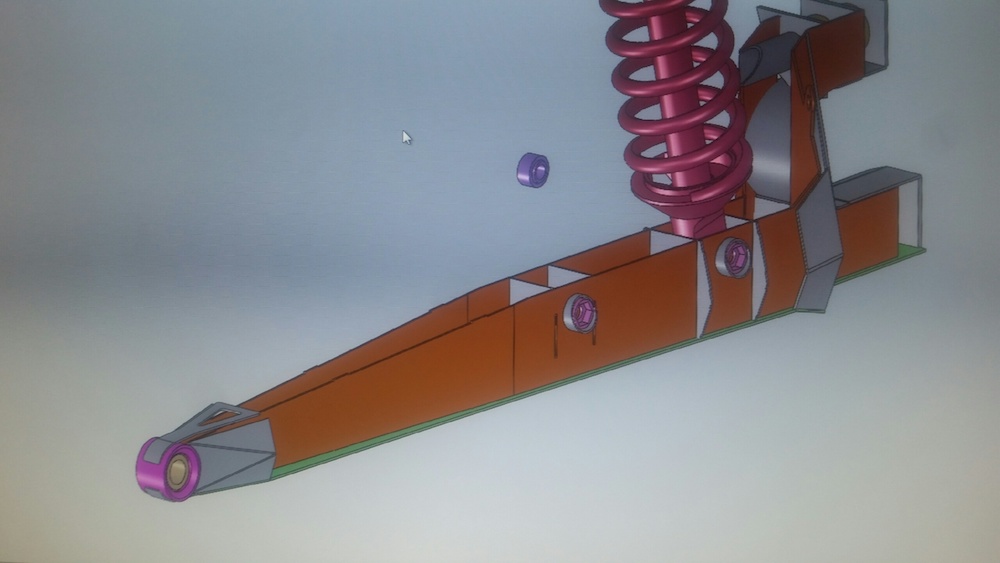
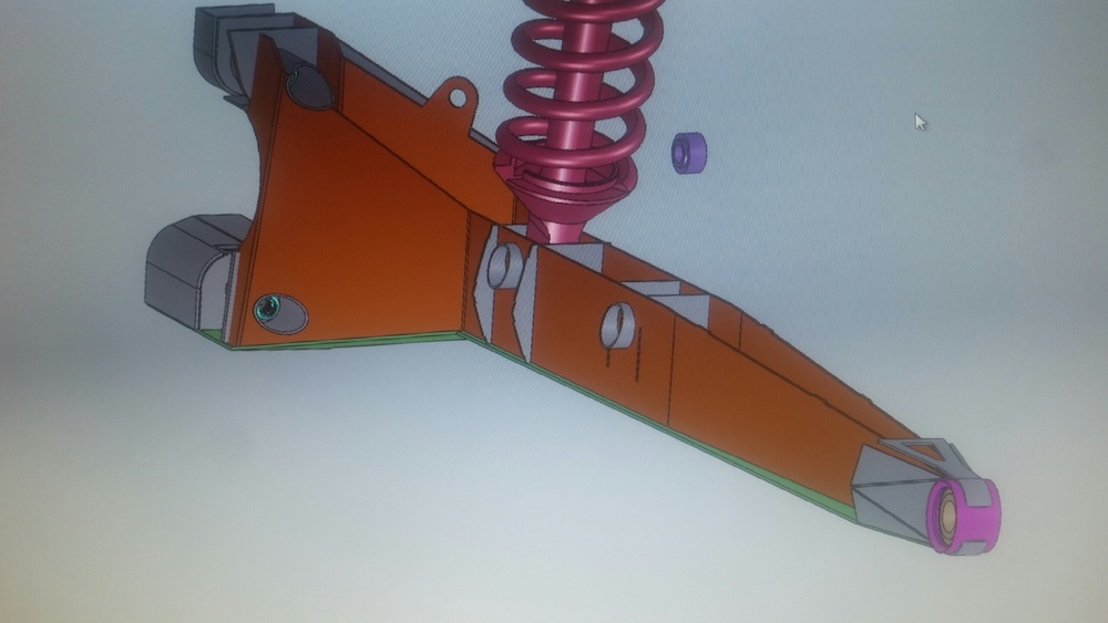
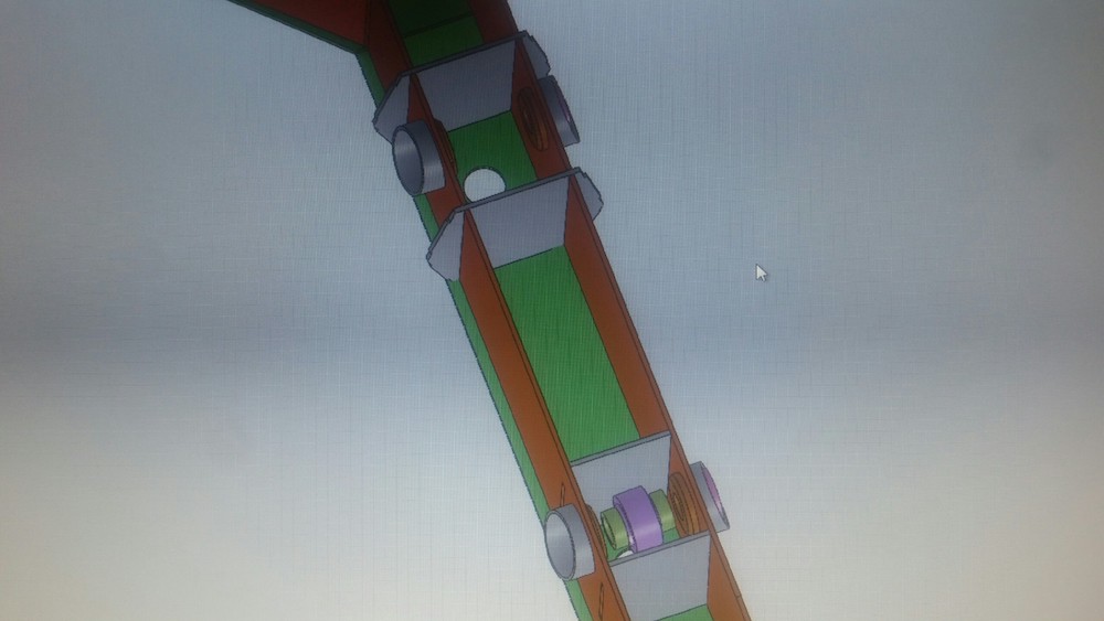


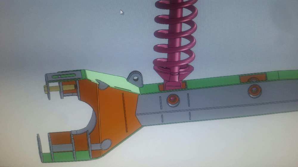
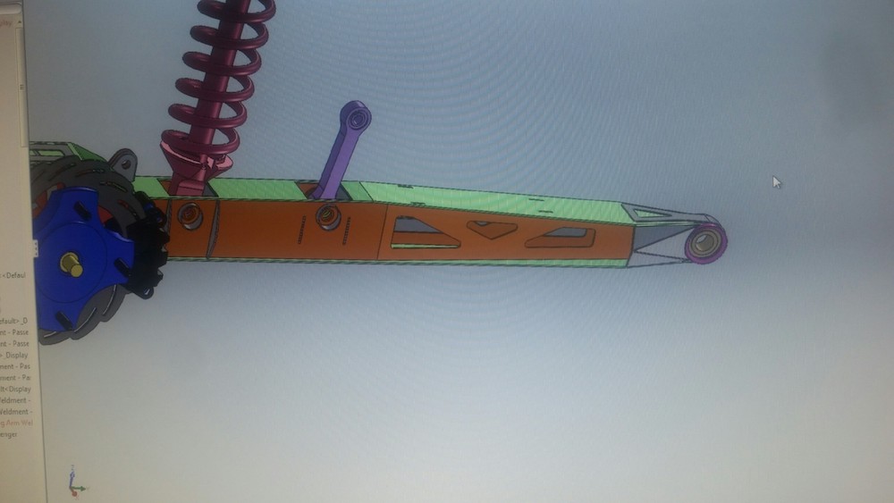
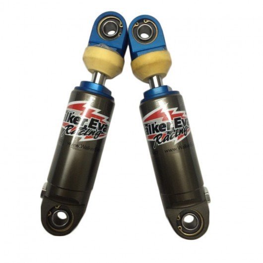
We designed the sway bar pockets to accommodate a piece made by [URL="https://www.klmperformance.com/walker-evans-400-00-003-can-am-maverick-x3-walker-link-rear-sway-bar-shock.html"]Walker Evans[/URL] - it replaces the solid link between the arm and the sway bar. I want to do a bit more research before I pull the trigger.
If I decide not to go this route, I'll machine some nice billet links with appropriate spacers similar to what's seen in the renderings.
Just like up front, everything on this arm, with the exception of the front pivots, uses 1/2" fasteners.
I should be able to fully assemble all the main components on the Mini-Raptor with a single 3/4" wrench. All fasteners have at least one capture so regardless if it's the head of the bolt or the nut that's being held, I only have to use one wrench to tighten.
Nov 28, 2017
Toe control rod goes here.
Obligatory nuuuuuuuut pocket doing it's job.
Dec 10, 2017
Rear arms and bulkhead design work is done and files have been sent off to laser.
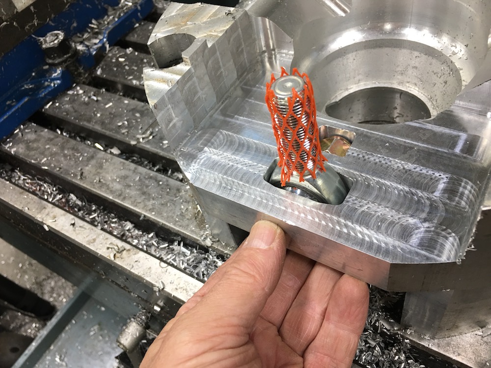
So the first rear carrier is done but done incorrectly. I had some tool offset compensation issues with my programming and the mounting ears came out wrong. I also wasn't happy with the back side of the carrier and the way it came out. There's too much material missing between the ears and there's not a good transition between the main body and the control arm.
Most of the issues (other than the offset) were due to how I was trying to hold the material to the table. The clamping bolts kept getting in the way.
Round 1.5 and a new prospective on how to do this and the second one's coming out much better.
Looks good from this side:
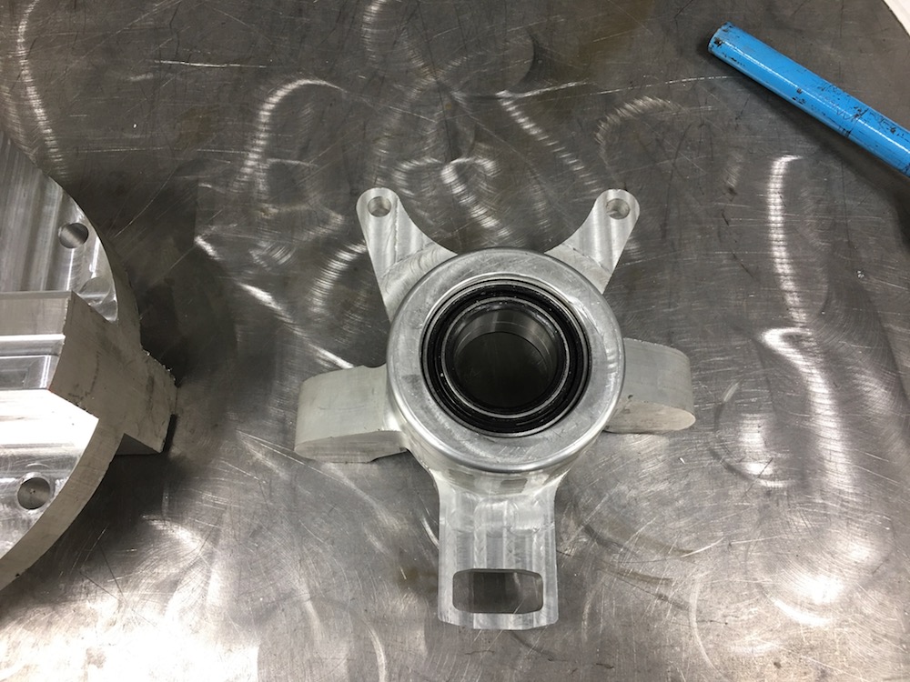
Not so good here.

Better view of the messed up back side - sometimes even with a CAD drawing there's a visualization that doesn't show up until you have the part in hand.

So I made two of these - all the material around the where I clamp it to the table was taken down to a workable height - no more too crashes/too short of tooling, clearance problems, etc.. The two sides are mirror images of each other and keeping track of which one was going to be the left and which the right was a pain. Had to make sure I started machining the correct side for the correct part.
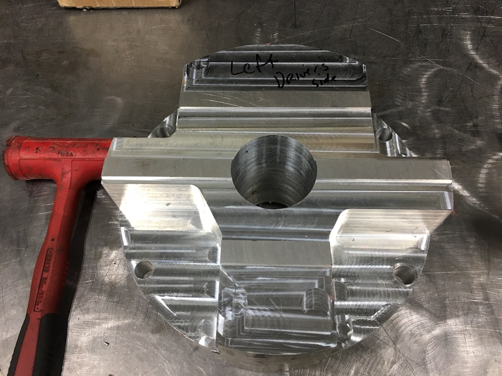
Bearing snout has been cut out, the transition between the body and the control arm is actually there now and I modified the caliper mounting area too.
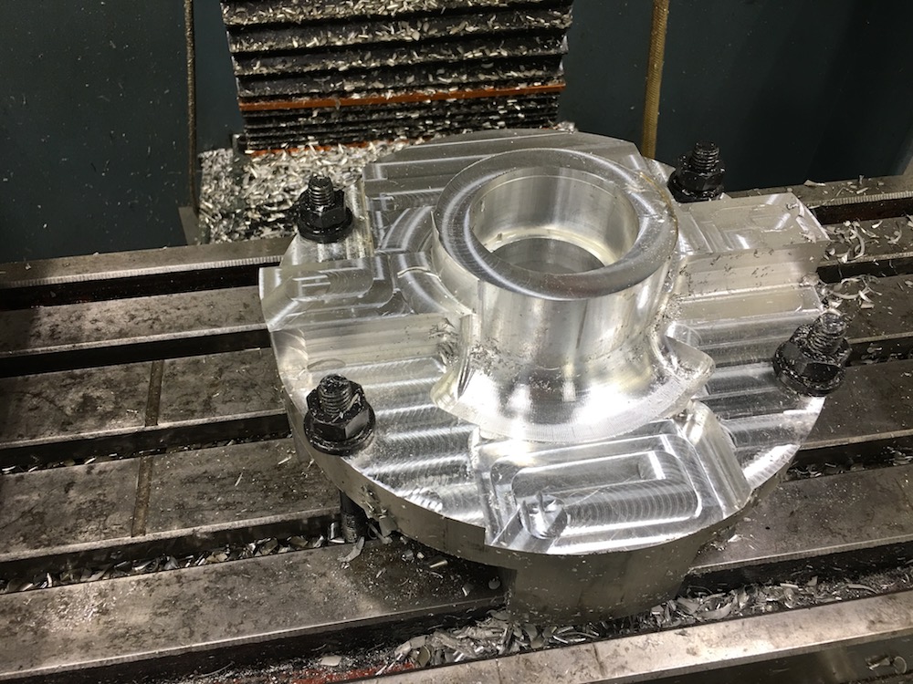
Outside of the mounting arms are now whittled out and blended into the body nicely and I have the pocket for the toe control arm machined out.

Hopefully I'll finish up this side today and get to flip it over and not remove as much material from around the back side as the first one had.
More to come.
Dec 11, 2017
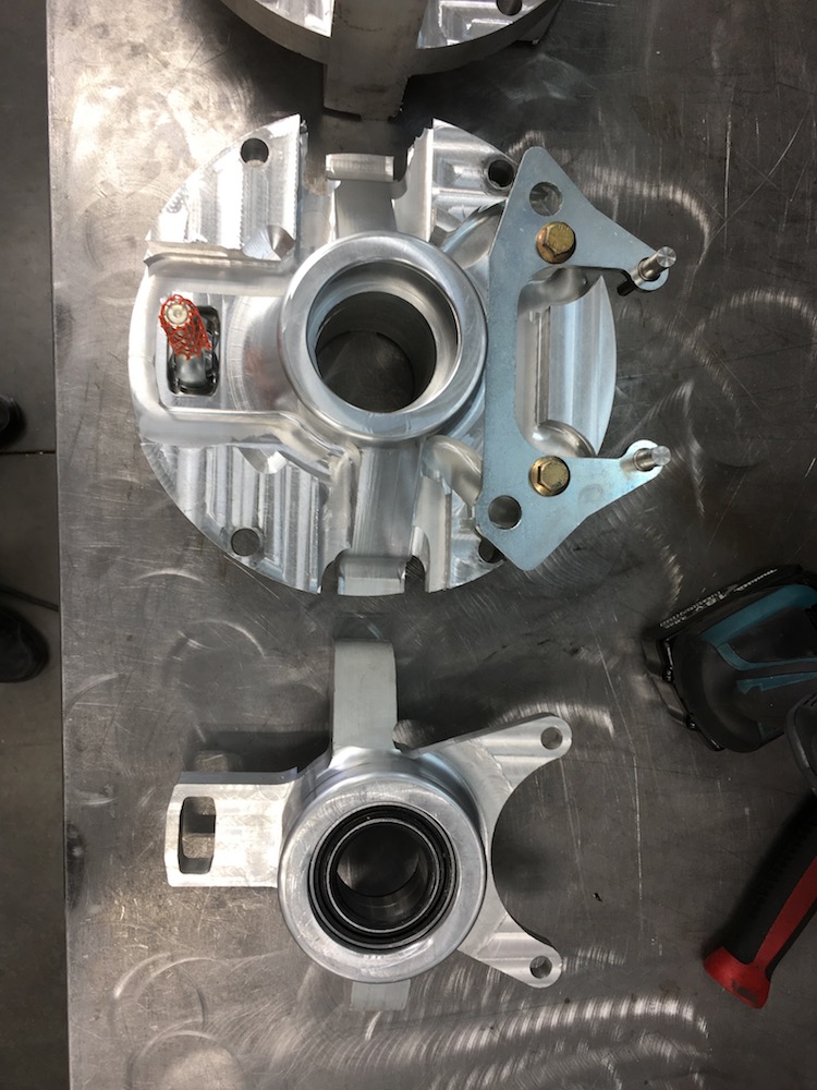

Got the outside of both carries done last night. Now it's flip over time and do the back sides.
Dec 13, 2017
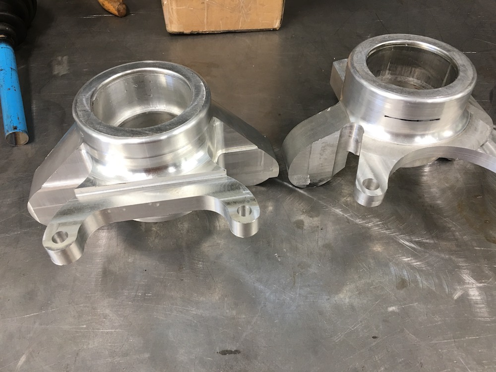
New one on the left, first (prototype) on the right.
Crap - forgot the nut pocket...
There's a gouge on the upper side of the left ear - missed one stupid line of programming and brrrp - there went some extra aluminum that wasn't supposed to.
And the BIG f*&k up... Notice the big missing spot on the upper side of the right hand ear??? Yeah, that one was bad. There's a uniball that fits here. I've filled in the missing notch with weld. This will be interesting. shit...
Big difference in the caliper mounts. More clearance, thicker arms, more better.
Tie rod mounting hole was opened up for more angular clearance.
Better blending of everything.
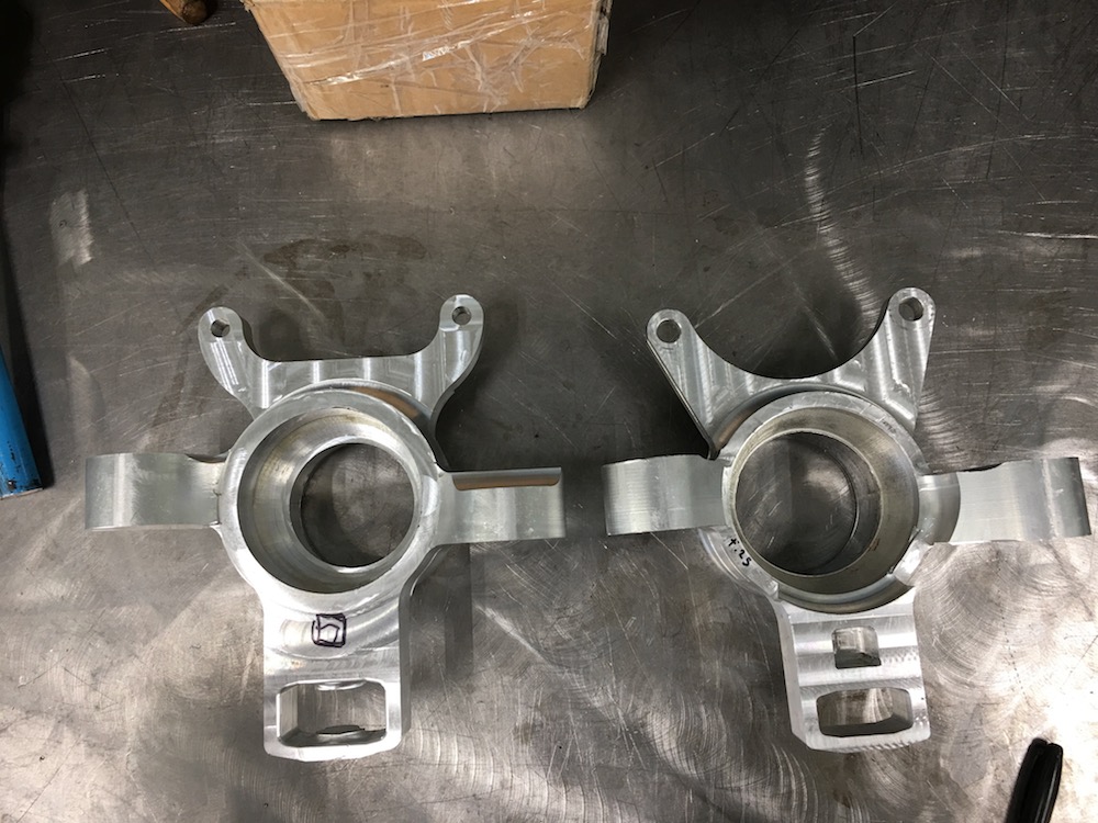
This gives an idea of the new ear profiles. They extend farther down the body and aren't cut off by the hole in the back side. I also filled in the spaces between the ears and the back side where the clearance hole for the CV was cut away in the material in the prototype. The back side is now flat and everything is blended to it.
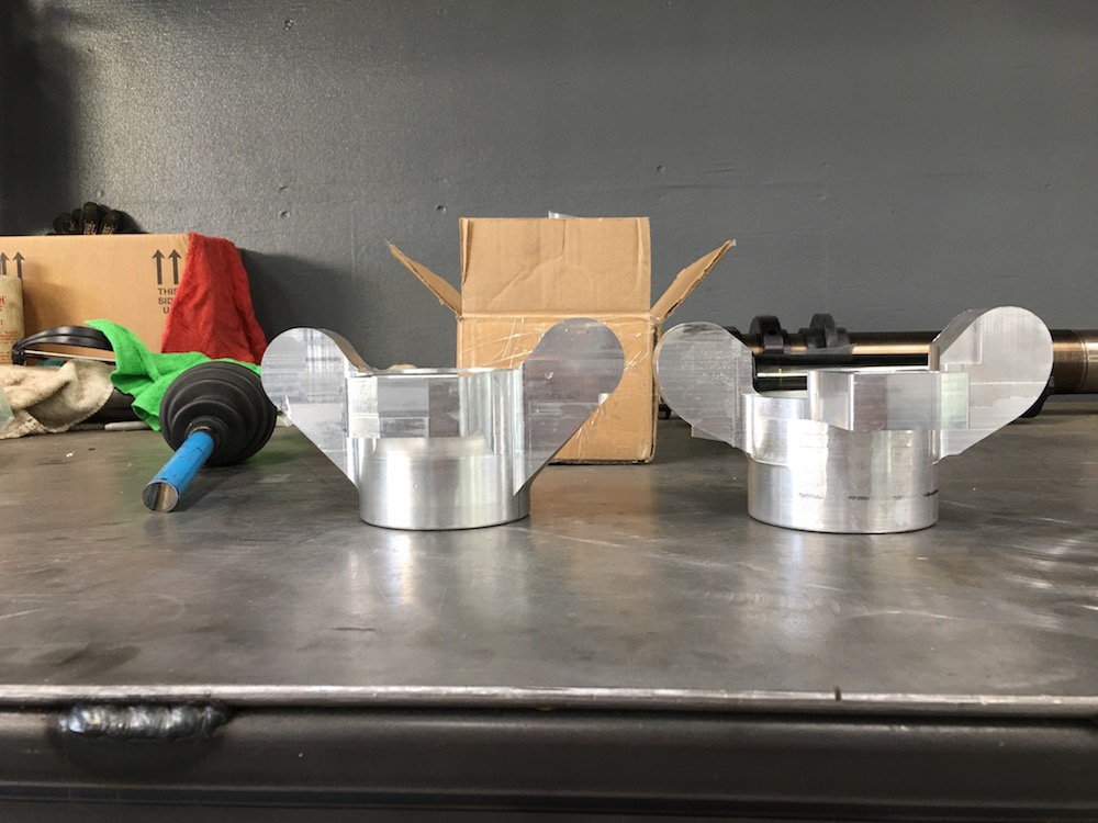
Caliper mount got modified. The calipers mount on .250" thick plates and the plates get bolted to the carrier. I recessed the mount into the body a bit more and the plate meets the blending areas really nicely now. Ears got thickened up by another .125" too.
You can really see how much father the ears go up the body in this pic...
Opened up the hole for the tie rod heim and then ball cut around where it mounts so it has a tad more clearance for angular deflection - don't think it needs it but hey, why not?
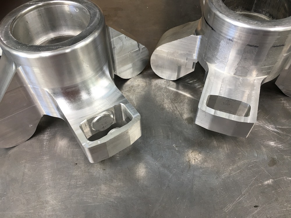
Original had minimal clearance.
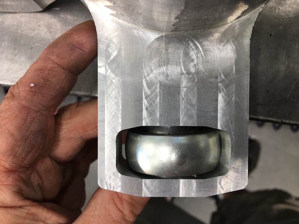
This one has lots of room.

I have to open up the back side a bit more so the CV falls all the way into the carrier - this was one of those hard to measure things that I decided would be easier to just chuck up again and cut the pocket as needed.

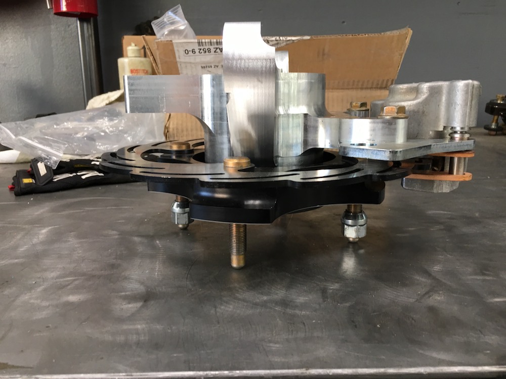
Side shot - caliper fits perfectly. You can see the step I mentioned above.
This also gives a good shot of the blending I did between the body and the steering ear and both sides of the caliper mount.
See the big half u-shaped piece missing from the ear? Yeah... shit...
I'll fix the problems on this one and the second one will be in process soon.
Dec 14, 2017
I'm having a ball!
yeah, bad.... It was handed to me.
First part of fixing my screw up - put the metal back. Fill it in with rod.

Fortunately this is on the compression side of the suspension so I'm not worried as much as I would be if it were on the lower ear that's in tension.
The desert and a KTM350 call - I must go answer. More later.
Dec 15, 2017
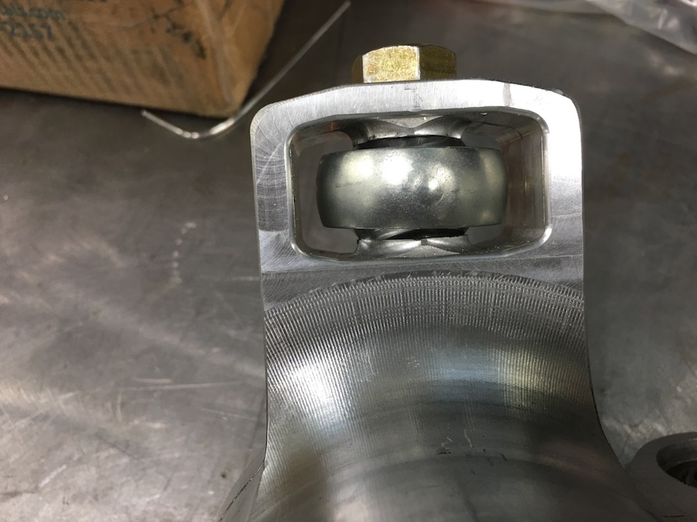
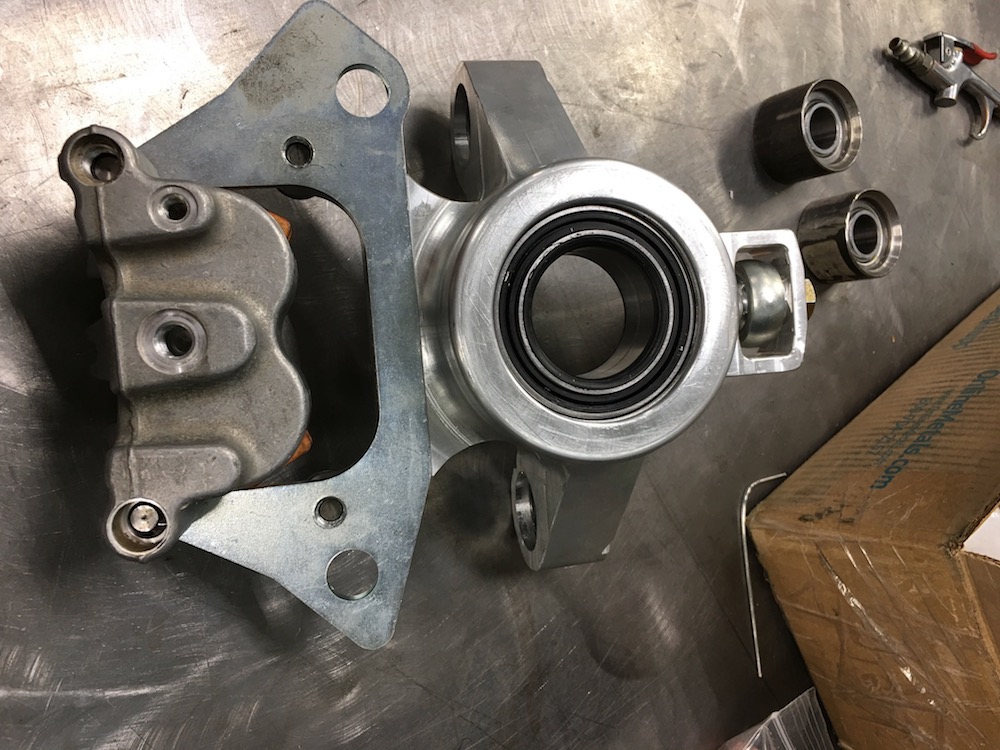
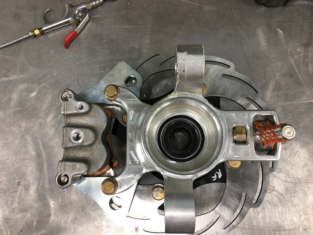
Right rear carrier is finished. From a 41 pound chunk of aluminum to under 4.5 pounds.Got everything done, blended, finished.


Dec 25, 2017
And then there were two!


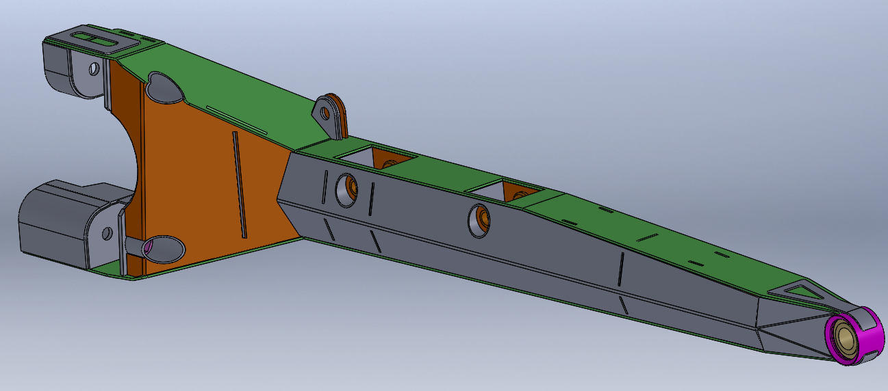
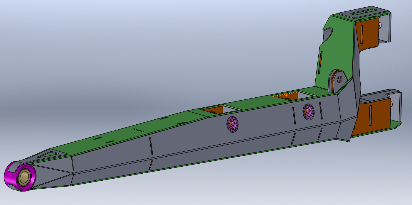
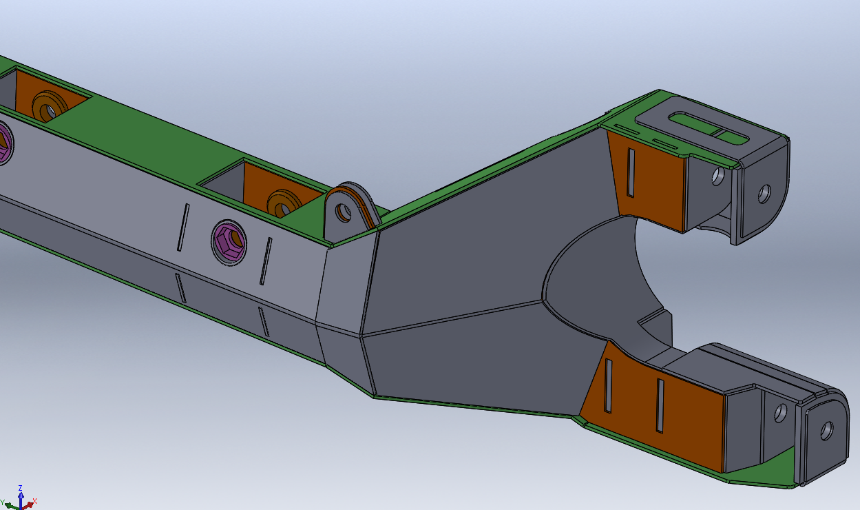
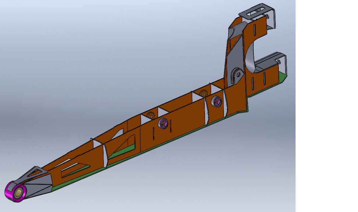
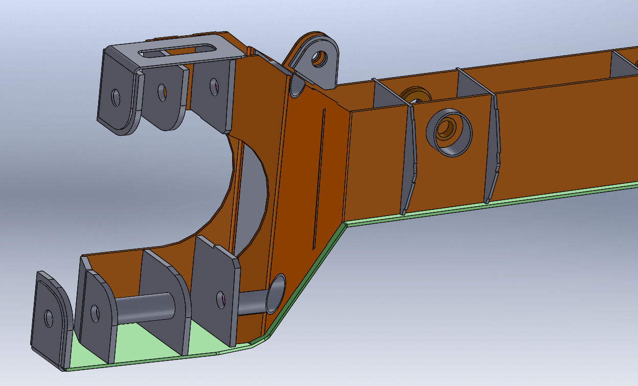
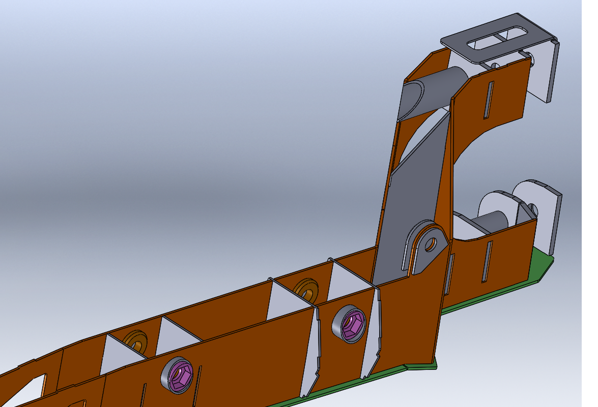
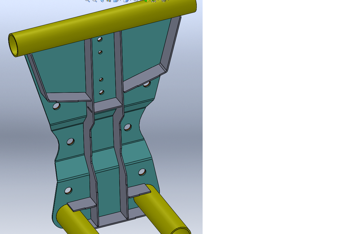
Here are the CAD renderings of the rear trailing arms and bulkhead. They're off at laser.





Dec 26, 2017
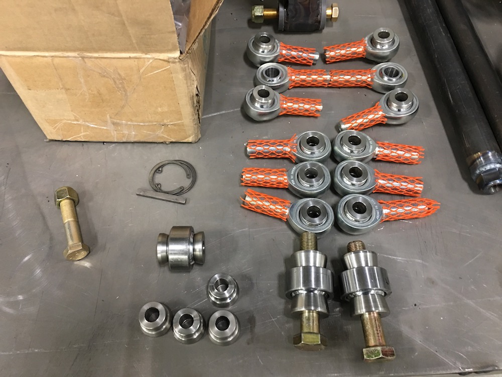
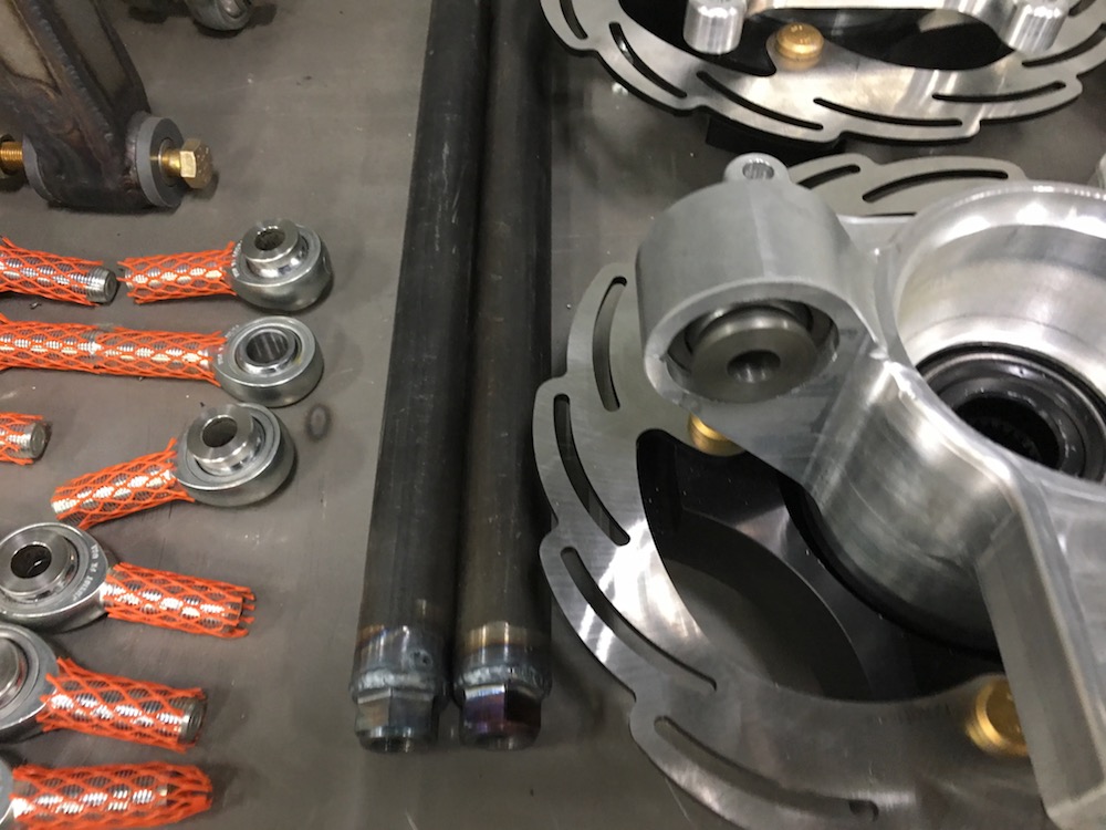
Spacer day!
I've turned spacers for every uniball and heim in the rear end. There's a bunch of the darned things too. 38 pieces total.
This concludes the building that happened up through the end of 2017. Click on the link below to be taken to what happens in 2018.
