

Home of K-fab

|
|
|
|
(9/5/99) is the rear suspension is finished - AGAIN?!?
(8/30/99) is the rear suspension is FINISHED!
(8/25/99) is the rear suspension is coming along great!
(8/24/99) The main chassis is FINISHED!! WOO HOOOOOOO!!! AND I've started on the rear suspension too.
(7/15/99) Little stuff that takes time - also known as "Three Steps Forward, Two Steps Back."
The Start of a New Chassis and all the little things that go with it.
The Stuff Inside the Chassis, formerly known as "Installing a Steering Rack"
 I now have the majority of the materials I need to get the chassis under construction. I received a new (real) bender this afternoon (4/27/99), ordered a bunch of parts from Continental Motorsports (my racing parts supplier) and I'm looking forward to spending some quality machining time this weekend.
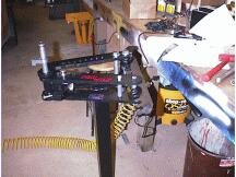
One thing I forgot is what a pain it is to use a masonry bit in old concrete. I spent the better part of two hours on Saturday (5/1/99) drilling four 5/8 inch holes into the concrete floor of my shop to mount the bender. As usual, nothing ever goes smoothly. The first bolt hole went right in and then 'regular life' kicked in and I hit rocks in the concrete on every other hole. Once I did get it mounted, I put it through it's first test and it passed with flying colors. I was able to bend a piece of 1-1/4" .083 wall 4130 chromoly tubing (what the main part of the chassis will be made of) with no problem. As soon as I get the rear carriers and front spindles finished and off to anodizing, I'll start the chassis work.
This is TOTALLY different from the machining phase! Earlier, I had machined a block of aluminum down to exactly 1.25" wide (the size of my main tubing) and then I machined thin tabs directly into the center of the ends of the block. This would be my alignment tool for my tubing and tabs. I drew out the basic shape of the car on my table with the lines representing the center line of the tubes. Next I used my alignment tool by putting the end tabs directly on the lines I had drawn, put the jig tabs against the alignment tool and then welded jig tabs to the table. This put all the jig tabs in the proper location to hold the tubing. The jig tabs would also help get the bends correct.
 I'm really impressed with my bender. The thing works really well. I was able to make duplicate bends with ease. Too bad my first set of tubes were the victims of brain fade. The bends were perfect, but the tubes I bent were too short! The next try worked out perfectly. The notcher, for mating the tubes where they are welded together, works great too. I have the basic parts of the lower frame set up and after I bend the nose section of the tubing up and with a bit more grinding and cutting, I'll be ready for the first welds.
Oh what fun last night was - NOT!!! While I was working on the chassis, a nasty storm came through. Five trees down, a lot of branches spread over the yard and a damaged trailer. As I was watching the storm go by my shop, I heard a large crack, watch the front end of my trailer suddenly bounce and then saw the tree roll off the top of the trailer. It crushed the roof on one corner, broke some shelving, a light and some other stuff inside too. What a bummer! (The trailer ended up being totaled)
Back to the building stuff...
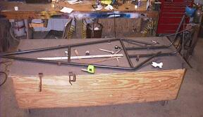
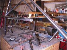
 I finished jigging up the bottom of the frame (while the storm raged on), got the basic bracing cut and fitted and then tack welded everything together. The result was a lower frame that pulled out of the jig - and went back in for that matter - with ease.
The tubing for the roll cage (1.25 x .095 chromoly instead of the .083 wall that the rest of the car is made from) was delivered this morning so I can start working on the upper sections of the frame. I'm to the point that I need to start pulling out the drive train, seat and other stuff from the Pilot. Once I get it stripped down I can start placing the major components on the lower frame section and start building around them. This will also give me a chance to go through the engine that's in the Pilot and FINALLY figure out what's dragging inside. This is going quicker than I figured it would! Hopefully, I'll have a car by the end of August.
 I FINALLY got a chance to work on the chassis last night. It's about time! Sorry it's been so long since I had a chance to update, but with the summer being here, family duties, motocross racing (I actually got a trophy this weekend!) and general keep busy stuff, I haven't had a chance to do squat with the car. BUMMER!!!
 My last stumbling block has been getting the upper cage to come together with the middle member and lower section on the rear of the chassis. After a lot of thinking, pondering and just plain confusion,
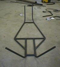
 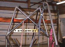 I figured out that I had to build the rear loop of the roll cage and work from there. I pieced together the rear loop (which, if I bend in a crash, I DO NOT want to be in the car when it happens - it's one seriously strong part!), put it in place and then began bending the upper cage rails.
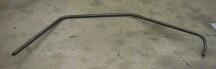 I went about bending it from the wrong end the first time (of course) and ended up with a useless piece of tubing. Naturally, I only had enough to do two frame rails and the cross members. Looks like I'll be placing a tubing order this morning! Can you say "AH *&%$#*&!!"?
(7/15/99) The past two weeks around here have been HECTIC!!! I've been able to get down and work on the car a little bit, but nothing that really stands out. It's been a lot of small "attention to detail" stuff.
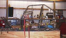
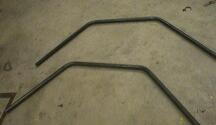 It seems that I'm to a point where I make three steps forward and then discover that I need to take two steps back. Take the roll cage for example. First I ran out of tubing and ended up being down for a week. I get the tubing, get both of the main tubes bent and discover that I need to change some of the vertical members in the lower part of the cage. The problem is that I'm mounting the suspension components directly to the frame tubing instead of in a mounting plate setup. These mounts put the pivot points farther in on the chassis and give me about one and a half inches more length on the suspension arms.
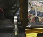 These mounts take quite a bit of time to make, and I only had to make twenty eight of them! The first set I made - for the upper a-arms - were the easiest (eight of them were needed - then I only ended up using six of them). Since the upper a-arm heims are 1/2", I took a piece of 1/2" tubing, and cut it to sixty millimeters. Next, I took a piece of 5/8" tubing and cut it 1/2" shorter than the smaller tubing - the width of the ball in the heim. I reamed out the 5/8" so that the 1/2" tube became a tolerance fit and then I pressed the two together. This makes a shouldered mount that the 1/2" heim will slip on. After that, I drilled out the mount so that the 10mm x 60mm shouldered bolt will slip in and the head of the bolt keeps the heim joint in place. Make sense? Now, I know you're thinking six upper mounts? But there are only four upper arm pivots. Correct! BUT, I'll set it up so that I will have two different mounting locations for the upper a-arms. This setup will allow me to tune the camber of the car as the suspension compresses.