

Home of K-fab

|
|
|
|
(11/7/99) At 1:44 a.m. the Moskito Comes To Life!!!
(10/30/99) The End is getting near?
(10/7/99) The Fire Suppression System is Mounted and the Brakes Work Too.
(9/18/99) The Pedals are in.
(8/20/99) The engine, tranny and steering rack are in.
(8/2/99) I'm working on the chassis again!
(7/15/99) Little stuff that takes time - also known as "Three Steps Forward, Two Steps Back."
The Foot Well; formerly known as "Installing a Steering Rack"
(7/15/99) The past two weeks around here have been HECTIC!!! I've been able to get down and work on the car a little bit, but nothing that really stands out. It's been a lot of small "attention to detail" stuff.
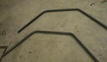 It seems that I'm to a point where I make three steps forward and then discover that I need to take two steps back. Take the roll cage for example. First I ran out of tubing and ended up being down for a week. I get the tubing, get both of the main tubes bent and discover that I need to change some of the vertical members in the lower part of the cage. The problem is that I'm mounting the suspension components directly to the frame tubing instead of in a mounting plate setup. These mounts put the pivot points farther in on the chassis and give me about one and a half inches more length on the suspension arms.
 These mounts take quite a bit of time to make, and I only had to make twenty eight of them! The first set I made - for the upper a-arms - were the easiest (eight of them were needed - then I only ended up using six of them). Since the upper a-arm heims are 1/2", I took a piece of 1/2" tubing, and cut it to sixty millimeters. Next, I took a piece of 5/8" tubing and cut it 1/2" shorter than the smaller tubing - the width of the ball in the heim. I reamed out the 5/8" so that the 1/2" tube became a tolerance fit and then I pressed the two together. This makes a shouldered mount that the 1/2" heim will slip on. After that, I drilled out the mount so that the 10mm x 60mm shouldered bolt will slip in and the head of the bolt keeps the heim joint in place. Make sense? Now, I know you're thinking six upper mounts? But there are only four upper arm pivots. Correct! BUT, I'll set it up so that I will have two different mounting locations for the upper a-arms. This setup will allow me to tune the camber of the car as the suspension compresses.
 The other twenty mounts are 5/8" and took even more time. These are three layer units. Basically the same as the 1/2" mounts, but the 1/2" and 5/8" tubes are the same length (60mm) and the last piece is 3/4" and it's also 3/4" shorter than the other two. By the time I was done making all the mounts, I had cut seventy six pieces of tubing, deburred one hundred fifty two ends, drilled seventy six holes - most of them took forty turns on the tail stock of the lathe
to plunge and return the bit - and then forty two pumps on the hydraulic press to push a piece together. It ended up taking all night to make the mounts.
The other twenty mounts are 5/8" and took even more time. These are three layer units. Basically the same as the 1/2" mounts, but the 1/2" and 5/8" tubes are the same length (60mm) and the last piece is 3/4" and it's also 3/4" shorter than the other two. By the time I was done making all the mounts, I had cut seventy six pieces of tubing, deburred one hundred fifty two ends, drilled seventy six holes - most of them took forty turns on the tail stock of the lathe
to plunge and return the bit - and then forty two pumps on the hydraulic press to push a piece together. It ended up taking all night to make the mounts.

 I also took the time to strip the Pilot down. I still have to pull the drive train out and make a jig for the mounting brackets that hold the engine and tranny in place, but that shouldn't take too long. I'll be able to take the mounting jig, set it in the back of the new car frame and build the engine/tranny mounts for the new car. I've done some test fitting of other parts like the steering rack, the brake pedal and the seat. As soon as I get the engine/tranny located, the seat will be very easy to put in.
I won't get a chance to do much for the next few days. I got my new trailer so I have to get it set up and I'm leaving Friday night to go riding (the motocross bike) in the forest of Southern Kentucky. Hopefully, I'll get a chance to work on the front suspension mounts, the seat mounts and the drive train mounts early next week. Getting these done should let me start the final mounting of the roll cage. Like I said, hopefully next week.
(8/2/99) I'm back in the shop working. (I had a MAJOR get off in the Kentucky Forest - fourth gear over the bars. I haven't hit the ground that hard in years!) I know that the pix above show that I was working on the roll cage, but I've discovered that I need to work a little lower before I could put the upper section on. I've made three forward steps - one big one and two smaller ones. One of the smaller is getting the seat installed. By getting it located and in, I now know how much room I have between the engine and the back of the seat. The Pilot had eight inches of room between the cross bar for the back of the seat and the front engine mounts. I was able to move the seat forward about two inches in comparison to the Pilot's chassis and in turn, I'll be able to mount the drive train about one to two inches farther forward in the new chassis. It should help move the weight bias forward quite a bit.
 The second small step is obviously the jig for mounting the drive train. After I pulled the engine and tranny out of the Pilot, I made up a jig to locate the mounting points of the drive system for the new car. I cut tubing that fit into the mounting points on the Pilot's chassis, ran bolts through them and then welded tubing in between the mounting points. Also, to make sure that I have clearance between the bottom of the chassis and the rear brake rotor, I dropped a locator arm down from the mounting jig. It looks like this setup is going to work great for getting the mounts in the correct spot.
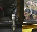
 The big step that I've made over the past couple of days is getting the front suspension mounts made and installed. After a lot more CAD work and a lot of careful measuring, I came up with the mounting point locations for the lower and upper a-arms. On the upper a-arms, I made two different mounting points on the leading arm. Having two different points to mount will allow me to change the caster angle as the suspension compresses. This will affect the way the car handles under compression - say after landing from a jump.
Trial fit of the heim joints shows that I need to grind down the tubes that they fit on just a bit, but it's not a big deal. The through bolts that hold the heim joints on work great, but because the tubes that they go on are just a bit long, the ball in the joint is able to spin instead of being locked down solid. This would not be good, as the wear on the ball and mount would be horrible. All in all, I'm really pleased with the way it's all worked out anyhow.
Next, I'll start working on getting the engine and transmission mounted, then I'll move up front and work on getting the brake and throttle pedals and steering box installed. After that, I'll start getting the roll cage assembled. Things are starting to pick up again!
(8/20/99) Where has this month gone??? The last line of the paragraph above made is sound like I was going to have a chance to work on the car (I thought I was!), but I haven't had much of a chance to do ANYTHING on the car the past couple weeks - there was the CART race last weekend at Mid-Ohio, a quick weekend jaunt with the family, and a battle with HORRIBLE engine noise in my van's stereo (No, don't e-mail me telling me that I have to ground the system better, it's something in the low level leads that I can't seem to isolate). Not to mention the little piddly ass work that I've still been doing on my new trailer. I guess that's why it's called 'Summer Vacation'.

 OK, enough rambling and back to the car stuff: Using the engine/tranny mount jig I was able to locate the mounts for the powerplant and get all but the outer rear mounts welded in. My first trial fit of the drive train turned out to work perfectly. I was VERY careful to make sure that I got the mounts perfectly centered and square to the rear of chassis (this took
a lot of trial and error work) so I don't end up with any binding or breaking problems with the drive shafts. I sure hope I that got it right!
OK, enough rambling and back to the car stuff: Using the engine/tranny mount jig I was able to locate the mounts for the powerplant and get all but the outer rear mounts welded in. My first trial fit of the drive train turned out to work perfectly. I was VERY careful to make sure that I got the mounts perfectly centered and square to the rear of chassis (this took
a lot of trial and error work) so I don't end up with any binding or breaking problems with the drive shafts. I sure hope I that got it right!

 One thing to come out of getting the powerplant installed is that the rear length of the chassis ends up being about six to eight inches longer than I expected (you can just barely see it in the picture to the above right, oops, my other right - aka the left). I'll be able to redo the rear of the car and shorten up the chassis' overall length quite a bit. Nice bonus, eh?
One thing that seems to be standard in building this silly thing is that each step I take just ends up pointing out that I have half a dozen more steps to do. An example is the seat. Installation of the seat was pretty straight forward. Cut a tube for the front mount, cut tabs for the seat to mount to, weld in tabs, bolt in seat. Simple. But then I have to make mounts for the harness, mounts for the anti-submarine strap, mounts for the wrist restraints. It just seems to add up and up. They aren't hard to do, but I want to make this car look as professionally built as possible, so attention to detail has been fairly high and it's this little stuff that ends up taking up huge amounts of time.
 Getting the steering rack in ended up being a total PAIN IN THE ASS!!! (Then again, it was my own fault.) When I started laying out the seating/steering/pedal arrangement, I was still in "Pilot" mode. I wanted to sit in a certain way, have the steering wheel in a certain spot and have my feet in a certain position too. The big problem ended up being that I was having clearance problems with the steering rack, the pedals and the area in front of the steering rack (basically where the front of the chassis turns upwards). I knew that I had to have the steering rack above the front mount of the lower a-arms, but the problem is that the front mount is about four inches up from the bottom of the chassis. This puts the rack up about five to six inches off the bottom of the chassis and then my feet hit the rack and I don't have room for the pedals. I was a touch stuck until a good friend of mine (who just happens to be a Formula 1 race FANATIC) said "Hey, why don't you just move your feet up like they do in F1 cars?" It was a stroke of brilliance - at least to me! I dropped in a cross brace just above the lower front a-arm mounts, sat in the car, put my feet up on the brace and realized that it was going to work great.

 First I cut a template out of cardboard and fitted it into the front of the chassis to get an idea how the rack would mount. I discovered that I'm able to mount the rack either above or below the template and have the option of having the input shaft of the rack sit either above or below the template. I cut the first mount out, tack welded it in and realized that I didn't get it right. So I cut another one, tacked it in and realized I screwed
up again! I was trying to make too many odd angles and get too fancy by cutting out webbing in the mounting plate. Finally, I got the last plate cut correctly, tacked in correctly and the rack in place. I went with the setup of hanging the rack under the mounting plate with the input above the plate. This gave me the room I need for my feet and the correct steering wheel angle and the proper placement of the steering rack in relation to the a-arms.
First I cut a template out of cardboard and fitted it into the front of the chassis to get an idea how the rack would mount. I discovered that I'm able to mount the rack either above or below the template and have the option of having the input shaft of the rack sit either above or below the template. I cut the first mount out, tack welded it in and realized that I didn't get it right. So I cut another one, tacked it in and realized I screwed
up again! I was trying to make too many odd angles and get too fancy by cutting out webbing in the mounting plate. Finally, I got the last plate cut correctly, tacked in correctly and the rack in place. I went with the setup of hanging the rack under the mounting plate with the input above the plate. This gave me the room I need for my feet and the correct steering wheel angle and the proper placement of the steering rack in relation to the a-arms.
 I
I Since I'm down and out working on the front suspension of the car, I've started working on the brake and throttle pedals. Mounting the pedals has just been another one of the "I'll wing it" steps. I wasn't quite sure how I was going to put them in. I didn't have enough room to put the master cylinders (MC) up above my feet or up by my knees because of my foot position over the steering rack. But, I did have room on the floorboard of the chassis. My next stumbling block was how do I actuate the MC if put the pedals in the plate that the steering rack is attached to. Simple, I make a plate that holds the pedal in the plate, mount the MC on the floor and make a link between the two. Sounds easy enough! I machined in a notch where the pedal actuates the MC so I could put in a heim joint, ordered another pedal, cut off the lower part of it where the pivot mount is, machine in a notch for another heim joint, make a link between the two and don't you know - it works! The action of the pedal is smooth and gives me more than enough travel. The link allows for adjustment so I can position the pedal as needed to make it comfortable too. Mounting the MC on the floor gives me enough room that I don't have to remote mount the reservoirs and it keeps the CG of the car low.
The throttle pedal is mounted in the same way as the brake pedal. I took the pedal that I cut the bottom off of, put a hole through it, made a Delrin bushing and pushed it in the hole and I now have a nice pivot point in the throttle pedal. I made a bracket that holds the pedal in the same manner as the brake pedal and mounted the whole thing to the steering rack plate. All I have to do now is figure out how to attach the throttle cable and I'm in business.
(10/7/99)  More of the front end of the chassis is now done. I have the brake pedal installed and completed - had to make a higher leverage ratio linkage for the master
cylinder actuation, and now I have the fire bottle installed too. I placed the bottle next to the master cylinders down under my legs. Once again, this helps keep the center of gravity down low and I've made great use of some normally "open" space on a car. All the new aluminum parts I've made (brake and throttle pedal mounts, steering box, steering wheel mount,
etc.) are being anodized and hopefully I'll have them back by the beginning of next week. When I get this stuff in, I'll actually be able to see the light at the end of the tunnel - I'm getting close to being done.
More of the front end of the chassis is now done. I have the brake pedal installed and completed - had to make a higher leverage ratio linkage for the master
cylinder actuation, and now I have the fire bottle installed too. I placed the bottle next to the master cylinders down under my legs. Once again, this helps keep the center of gravity down low and I've made great use of some normally "open" space on a car. All the new aluminum parts I've made (brake and throttle pedal mounts, steering box, steering wheel mount,
etc.) are being anodized and hopefully I'll have them back by the beginning of next week. When I get this stuff in, I'll actually be able to see the light at the end of the tunnel - I'm getting close to being done.
I've come to a point that the major components of the car are finally done. Now it's a huge amount of small stuff. Things like frame bracing, making the fuel cell, wire harnesses, running brake lines and finishing out the engine compartment. If you look closely, you can see the two diagonal braces I've added on the sides and the brace between the front shock mounts. The car is about 95% done. I will hopefully be taking the first test run in the next couple of weeks and then set about some serious testing/hammering sessions. I'm really fired up about getting in and running it. I'll keep reporting as I start wrapping up the making of this new Stadium Lite.
 The fuel tank was pretty simple to do, but it took a bit of time. I started out by making a card board box that fit in the location I had chosen and then began to modify the box to fit into the area. I had to lean the top of the box back to give me clearance from the seat and also make room for access to put fuel in.
After getting the cardboard template done, I transferred it to a sheet of 1/8" 3003 aluminum, used the plasma cutter and knocked out the expanded shape of the tank. A couple more passes with the cutter so I could bend the sides and I had the basic shape of the tank formed. I had the corners welded (I don't weld aluminum) to firm up the tank and then I went about getting the fittings located and tank mounts formed and located. Back to the welders and I had a fully formed, finished and ready to install tank.
 Getting the throttle pedal linked up took a bit more work. I had to make a mount on the pedal for the arm that the throttle cable attached to, modify the arm so that I could rotate it to adjust for the travel of the arm (so I wouldn't pull the throttle slide through the top of the carb at WFO) in relation to the travel of the throttle pedal, and I had to modify the length of the throttle cable too. Once I got that done, I had to make stops to keep the pedal from traveling too far in either direction. I also made a small shield to keep the cable from getting tangled up with my foot since the pedal end of the cable has about six inches of the inner cable exposed from the point where it mounts to the frame to where it attaches to the pedal.
 Also, while I was working up front around the pedals, I installed the battery box. I located it right between my feet. It's a very simple installation, as all I did was weld the battery box to a pair of square tubes and mount the assembly between the front frame cross bar and the bar between the front shock mounts.
The dash board was the final part that I worked on. Not much more than making a few mounting tabs, drilling some holes for the components (choke, ignition switch, starter button, fire extinguisher pull). I still have to locate some more of the dash items, but I'll do that as I wire the car.
To finish the Moskito, I still have to make the body panels, do the wire harness, mount the expansion chamber and muffler, make a fire wall behind the seat and finish up a lot of other small things, but it shouldn't take too long. I'll probably try to get a test ride in before I start the body panels. It's getting close!
(11/7/99) After three nights of sitting on the front tire of the Moskito, wire cutters, soldering iron and Pilot wire diagrams in hand, I pull the choke, turn the ignition key, hit the start button and the Moskito came to life! I didn't run it long, as it has no water in the radiator, wires hanging all about and I was using the wrong fuel, but what counts is that it STARTED!!!
Getting the wire harness set up has been a daunting task! The Pilot was full of "safety features" - meaning that if you didn't have the thing in neutral or the run switch in the correct position it wouldn't start. Also, the Pilot's wire harness had a HUGE amount of redundant wire. I have spent the better part of twelve hours chasing down the wires that aren't needed (lights, dash board stuff, parking brake harness, etc.), relocating junctions, trimming lengths adding sensor lines and in general, customizing the harness to the Moskito. I still have to wrap the harness up and add a couple more instrument grounds, but the end is in sight. Hopefully, I'll get to take the first test run later today (Sunday) or tomorrow.
In the past week I've also finished mounting the expansion chamber and muffler, finished the fuel tank, installed the main belly pan and finished out the dash board too. I'm still looking at shock valving, the fire wall and body work, but it shouldn't be too terribly long before I'm actually DONE.
IT'S ABOUT TIME!!!!
(11/12/99) Go ahead, call me stupid - or too ready to go testing....
Over the past week, I've been doing little "detail" things on the Moskito. I finished the wire harness - still have to install the mounts (tonight), I've made the belt shield, repacked the muffler, finished the dash board, purchased the air filter and done some other small things too.
During the past two days I've been cruising around the yard (four trips so far) seeing how the Moskito feels and checking everything out. I'm really happy with the preliminary "drives" as the car seems to have a lot of front end bite, feels like it transfers weight pretty well from acceleration to braking and in general I like it. The front end was WAAAYYYY too soft, so I worked over the front shocks last night and it feels better now - rear shocks are tonight. The problem is, that in my haste to play I managed to overlook two little bolts - the radiator mounting bolts.
So, here I am taking a couple "yard laps" this afternoon and as I slow down to drive off a landscape ledge (about a three foot drop) to see how the new front shock settings react, I'm suddenly engulfed in a nasty smelling white cloud. I look back and the engine is pumping radiator fluid onto the expansion chamber and there's a nice white smoke trail that starts about fifty feet behind me. I also notice that there is no radiator behind my head. "What the heck?" Wait, there's the radiator - but it's laying down horizontally on top of the carb. "Huh?!?" Then it dawns on me - "You Dumb Ass - you forgot to tighten the radiator mounting bolts!" I noticed a couple nights ago that they were not there and even went so far as to put the bolts and nuts in place, but dummy here forgot to TIGHTEN THEM! When the radiator fell over (who knows how early into my ride this afternoon), it managed to pull loose the line that feeds it. This in turn let all the fluid start to pump out and make a mess. I bet you can guess the first thing I'll fix tonight!
Return Home