
Home of K-fab
|
|
|
|
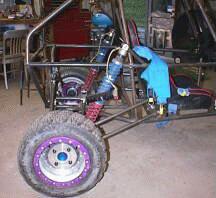
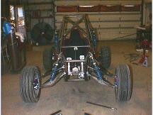
(9/26/99) I have no new shocks BUT, I have a ROLLING CHASSIS!
(9/18/99) is that I have Pedals and the Master Cylinders in - and I'm STILL waiting on front shocks - an editorial on Axis
(9/6/99) is SIX upper a-arms should be enough! (What am I thinking?)
(9/5/99) is the rear suspension is finished - AGAIN?!?
(8/30/99) is the rear suspension is FINISHED!
(8/25/99) is the rear suspension is coming along great!
(8/24/99) 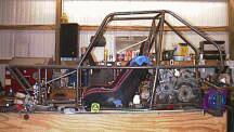
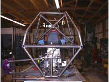
This weekend has been VERY good to me! I actually managed to finish the roll cage and the major framework of the chassis. After fighting with how I should bring together the rear end of the car - the lower cradle, the side tubes and the upper cage tubes together, I had a vision - well, uhm, it suddenly became clear. I had been trying to be fancy and bend the upper tubes around and down to mate into the lower cradle tubes, which were already bent upwards, AND tie them into the side rails. For my limited abilities in the art of tube bending (it really is an art!) this was way beyond me. So what I did was get smart. (I looked at the back of the Pilot.) I brought the upper tubes from the cage down to the side rails and then just added in the tubes that go from the side rail to side rail and also down to the engine cradle. Perfect! These down tubes also gave me great tie in points for the rear transmission mount. They triangulate great, giving a lot of strength to the rear of the car.
 Oh yea, Richard's three rules of welding: 1) Don't do a bunch of welding without a shirt. My chest is sunburned pretty badly. (Dork!) 2) Don't lean up against a joint that you've just welded. I don't know which gets your attention quicker, the sound of the sweat on your arm sizzling or the sudden burning sensation. Fortunately it wasn't bad, it just made me jump. 3) Don't accidentally pull the trigger on the welder when your trying to get the wire in place and you have your hood up. The blue flash followed by the spots that stay around afterward are a pain in the ass. - And you thought that camera flashes were bad...
 I still have bracing that needs to be added into the chassis, but I'm at the stage where I can start mounting the suspension. Until I get my front shocks I can't do much of the front suspension. I need to have the shocks to locate the mounting points in the lower a-arms. I can do the upper a-arms, but I've decided to do the rear suspension first.
Speaking of rear suspension - I'm about 2/3rd's done with it! First I made a jig that holds the rear carrier in the correct location in relation to the chassis. This point is where the links are all horizontal and give me the widest measurement (remember, 68 inches?). I've made the rear links and drag links (and spares of each), installed the front drag link mounts and started working on the rear link mounting bar too. I'm at a small stumbling point as to where and how I will attach the inner mounting points, but I should be able to get them built in pretty easily. After I get the rear links mounted I'll do the rear swing arm - what the shock will attach to - and the upper shock mounts too. This will require more chassis bracing, but that's no big deal.
(8/25/99)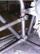
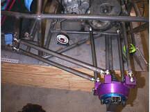
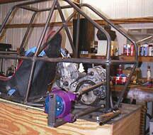
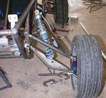
The rear end is almost complete. Last night I was able to get the rear link mounts in - and as a bonus, tie the rear transmission mounts in too. I still have to get the inner front link (the loose link on the left, heading towards the disk)- I'm calling it the 'swing arm' since that's the link the shock will attach to - mounted and I still have to make the swingarms too. The setup looks like it's going to work perfectly.
As I planned (hoped), I have at least fourteen inches of travel available in the rear end. I'll probably use about thirteen of that. I started trying to figure out the mounting point for the shock on the swingarm and also the upper shock mount too, but it was getting pretty late and I was pretty tired. Maybe tomorrow night. The problem I'm running into is that I have to figure out three different points in space. Two of them are pretty straight forward - actually, it's one point on the chassis where the upper shock mount is and 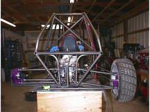 then one point on the swing arm, but that one is really two points in space; full extension and full compression of the suspension. What happens is that the farther out (towards the rear carrier)on the swingarm I get, the longer the travel is (makes sense). I have eleven inches of shaft travel from the shock, so I need to find a point on the swingarm that moves the same amount of the shock shaft while I have thirteen inches of wheel travel. So far, not hard to do, but where the trick comes in is when I lay the shock over towards the rollcage's main frame.
 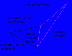 Now, I'm dealing with a triangular pattern where one leg represents the vertical travel of the swing arm, on leg represents the fully extended shock and the last leg is the shock at full compression. In the drawing to the right, the two black lines represent the swingarm and the three purple lines represent the shock. The swingarm is shown in both full compression and extension, as is the shock. The short upright purple line represents the vertical travel of the shock's lower mount as it goes from full extension to full compression. This travel - about thirteen inches - comes from the total shaft travel of eleven inches when the shock is laid over. You have to visualize the purple part of the drawing actually being ninety degrees to the swing arm. These three points are what I have to go out and locate on the car now.
(8/30/99) 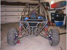
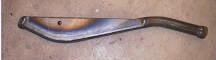
The rear end is DONE! The past ten days or so have been the most productive I've had in a LONG time. I was able to get the major tubing of the chassis and roll cage done, the rear suspension finished and quite a few smaller parts made too. Each night, after the family has gone to bed (usually after 10 p.m.), I've made my way down to the shop and started working, usually until 2 or 3 a.m.. The main parts of the rear suspension were really not that hard to make. Machine a shoulder into a nut, press the nut into a tube, weld nut to tube. The swingarms of the rear suspension took a bit more work, as I had to bend the tube, cut plates and weld it all together, but still, not a lot of "thinking" work. - oh, I had to cut down the inserts that go into the eyes of the shock heims so they would fit in the swingarms.
 After getting the suspension installed on the car, I had to test it, so I pulled the chassis off the building table, set it on the ground and bounced on the rear end. It feels great. I didn't notice any binding, funny movement or anything. I'm really happy with the results.
I still have a small tube to fit in up where the top of the shock mounts to the frame, but that's a quick install. I have to do the final welding around some of the structures too. As I build a section, I'll usually tack the tube or what ever in place, make sure everything fits correctly, run a small weld along an edge to hold it and then go back later and do all the finish welding on the sections that I've been working on - go back and see the Welding Rules - this is where they come into play. (:
(9/5/99) 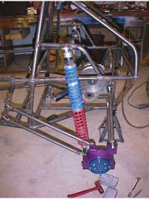
Gee, what was I saying about the rear suspension being done? I started working on the rear axle prototype earlier this week (forgot to take pictures, darn!) and discovered that at full extension there was a slight binding problem in the outer CV. I had fifteen inches of ground clearance and almost twenty inches of travel - somewhere, I'd messed up on my suspension calculations BIG TIME! Not only did I have about two inches too much drop but at full compression the wheels were about five inches ABOVE the lower frame. Bottoming out would not have been much fun. Back to the drawing board. I'm still not sure where I screwed up, but the upper shock mounting point on the chassis was way too far forward and the shocks were laid over too much.
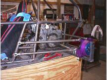
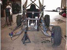
This time, instead of trying to calculate everything with AutoCad, I went "low tech" and used a ruler, a level, a tube with holes that represent the shock at extension and compression, a piece of cardboard and a pen. First, I put the chassis up on blocks (fourteen inches of ground clearance) and positioned the rear carriers in the location representing full extension. Then, I secured the cardboard where the upper shock mount was. I put one end of the tube into the shock mount on the swingarm, put the pen in the upper hole on the tube and drew an arc on the cardboard. I did the same thing with the suspension in full compression position. Where the two arcs met is where the top of the shock needed to be mounted. Take a look at the two pictures and you can see how much of a difference I needed. Some more tube bending, a set of mounting tabs and more welding and I had new - and correct - shock mounts in. I still have to add in a little bracing - but then again, I still have to brace the entire chassis when I'm done getting the major parts finished.
(9/6/99) 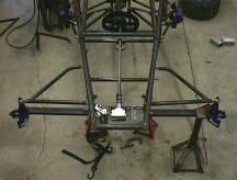
So, I head down to the shop yesterday afternoon thinking "I'll get started on the front end." I started out the day by finishing the rear shock mount bracing, then I attacked the front of the car. I made my jig to locate the front spindles, clamped it in place and mounted the spindles to the jig. I decide that the upper a-arms would be the place to start. (They ended up being very easy to make.) I cut a piece of tubing to fit between the front chassis heim joint and the upper spindle heim joint, welded in the nuts and "Ta-da", tube #1 is done - simple!
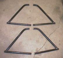 Now, as I've built this car, I've made spare parts as I go along. I have a complete spare set of rear suspension links and swing arms, an extra steering tie rod, three sets of rear axles - things like that. One thing I've tried to do as I make these parts is make them as universal as possible. The upper front a-arms follow suit and are neither left or right. The same piece will work on both sides. I figure that a couple spares is just fine. BUT, for some strange reason, I decided on the number SIX for the front end! I got into "production mode" and began to knock out six of each part. I made five more tubes that were exactly like the first, ready to bolt in. I put the bend in the tube that goes from the spindle to the rear heim joint, welded in the nut and cut and notched the tube to mount up by the spindle heim. A quick weld and there it was; A-arm #1. Five more just like the that and I'm ready to assemble the group. I made a jig on the assembly table from the first a-arm, welded the others together and there they were - six a-arms, ready to bolt in. Then it hit me. What in the world was I doing? SIX arms? SIX? O.K., I can see one spare set, but three complete sets? Guess I just got into the building mode a bit too much! Oh well, the front end will be "crash ready"! Maybe it's a sign that I'll be making another chassis for next year? - sheesh, what AM I thinking NOW?
I'm SUPPOSED to see my front shocks this week (I only ordered them four months ago). As soon as I get them, I'll start the lower a-arms. The front of the arm will be very similar to the rear swing arms. The shock will mount in the same manner as they do in the back end. I intend to take the front axles to get them threaded and heat treated tomorrow and they'll be ready to install into the spindles about the same time I finish the lower arms. I'm gonna end up with a rolling chassis before you know it! Hopefully, I'll have a running vehicle by the end of the month! (Oh please Great Axle God, let them be done soon.)
I am finally understanding ATV Racing's frustration with getting shocks from Axis. I have been contacted by quite a few people through this web site asking me about shocks and telling me that they've been put off over and over (usually told "Two Weeks") by ATV when inquiring about long travel suspensions for the Pilot. Well, I'm here to tell you that IT IS NOTATV's fault. Neil said that he's considering finding another shock manufacture if Axis doesn't get their act together.
I ordered a set of shocks for the front of the YDR Moskito FOUR MONTHS ago and I'm STILL being told "next week". Axis' products are top notch and probably the nicest overall package that I've seen. They rank right up there with Ohlin's and Penske's products. The tolerances are very tight, the compression adjustment knob actually does something (one click on an Axis is like 4 clicks on a Fox), they are very easy to revalve/rebuild and the quality is second to none - putting Fox's to shame. The big problem is the service. I talked to Neil at ATV yesterday and he was laughing saying "See, it's NOT us! Axis keeps telling us it's gonna be two weeks also. I tell my customers what Axis tells me, Axis doesn't come through and it makes ATV look like the bad guy." So, if you are waiting on a Long Travel suspension from ATV, and you are hearing "two weeks", tell them that you are gonna call Axis and ask THEM where your shocks are. Ask for Doug or Mike - Doug is easier to get hold of. You can reach Axis at (209) 368-5046. Don't be nasty, just say you want a straight up answer.
When I started designing the Moskito, I wanted a motion ratio around 2:1. This is the amount of travel of the wheel compared to the shock travel. Up front, I needed a shock with a travel of 6.5 inches and a body length (eye to eye) of 19.5 inches. Axis said no problem We'll have them in about a month for you. They were in the peak season for supplying dealers with shocks and were very busy. I figured that a month would be no problem. I knew that I wouldn't need the shocks for at least two months. A month goes by - no shocks. OK, no problem. Another month goes by - no shocks. I call Axis and can never get any sort of answer on the status of my shocks. Another month goes by - STILL no shocks. I call and demand to talk to someone other than the secretary (she's very nice, so don't pick on her) - no body ever calls back. I begin calling them daily and finally I get Doug. "Oh, your shocks are about ready, we were waiting to hear from you about the spring rates and damping you wanted." he says. "WHAT??? I told you guys up front what I wanted - spring rates, change in damping compared to the front long travel Pilot shocks, and the shaft travel and eye to eye specs." He comes back and says "the shocks we will have ready for you (in a couple weeks) are 17.5 eye to eye." "WHAT??? NO! NO! NO! 19.5 eye to eye. Hell, I HAVE a set of 17.5 already! Why would I have a custom set made if I already had a set?". Dead silence on his end. Then I get the standard, "I think we can have them ready in a couple weeks." Yea, right! Two more weeks go by and guess what - no shocks. I call and ask him what's the problem now. "Bad plating on the shafts." - It happens and Neil had been told the same thing. "We should have them ready by the end of the week." So, I call at the end of the week and I get the typical answer - we'll have them ready and ship them next week. They were supposed to go out Friday the 10th. Even Jay at ATV said Axis told him that they would go out the 10th. Wednesday comes and I have no shocks. I get on the phone, talk to Doug and he hims and haws around - "uhm, err, hang on" - I can hear him talking to someone - "Uh, the shock bodies are coming off the lathe as we speak and the anodizing will take two more days." I'm thinking "sure they are". "We should have all the components ready to assemble by Monday and they should go out middle of next week (9/20)." I told him that I'd be calling on Tuesday morning (9/21). If I'm given the run around, I'll be pulling the 17.5 eye to eye shocks off the Pilot and rethinking my front end's shock mounting points and canceling my order with Axis.
I'm stepping off my soap box now.
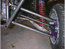
 The front parts of the lower a-arms are done. I've made two sets (NOT three). These look like the rear swing arms. The shock mounts in the webbing, the same way the rear shocks mount on the rear a-arms. I am using the front shocks off the Pilot to get an idea of the angle the arm is going to have to lean (as viewed from the side of the chassis) so that the upper a-arm and the shock don't occupy the same place in space when the suspension goes through it's motion. That would be bad. My big problem is that I'm to the point that without the correct shocks, I can't get the lower a-arms finished. I need the shocks installed on the car to give me the correct positioning of the arms before I can weld in the tube that goes from the spindle pivot back to the chassis. I know, "Two Weeks".
I'm also going to have to go back and redo the rear mounting section of the a-arms. The way I have them attaching, the heim joints come out perpendicular to the chassis. That's fine for the front of the a-arms, as they come pretty much straight out from the side of the car. But, the back point of the a-arms go in at about a forty five degree angle. If you take a look at the picture with the upper a-arms, you can see how I had to bend the arm to make it work. This ends up being a weak point. If I take a hard hit from in front of the car, this bend will bend even more and let the suspension collapse. I'll just cut the tubing with the bend in it off, make a mount for a heim and replace it with a straight piece of tubing. I'll redo the mounts on the chassis so that the line between the rear a-arm mount and the spindle is straight and this will let me make an adjustable upper link. By using both left and right hand threaded heims, I'll be able to adjust the caster quite easily. Just loosen the jamb nuts, turn the tube and instant adjustment is had. I'll take pictures and post them here when I get it done.
 First, a quick step back up on my soap box - well, sort of. As I had mentioned earlier, I was going to call Axis on Tuesday (9/21) and check on my shock status. I got the same stuff. "We're waiting on parts to come back from plating. Yours are the first in line to be put together and send out. Hopefully we'll have them finished next week." I said "OK" and right then and there, my mind was made up. I was going to make the shocks off the front end of my Pilot work. I called Axis back on Wednesday and Dana (the secretary) said, "I get the feeling this phone call is bad news." I confirmed her feelings and said I was canceling the order. I'd had enough. She actually agreed that this order had gone way over the line and had taken too long. So, that done, I turned to the shocks I have.
Off the soap box - for the last time. (Let it be known that I still believe in Axis' products. They make a superior coil over shock and I'll continue to use them. I don't know what the true reason for the delays were, but after four and a half months, I quit.)
 The first step in getting the front end done was get the upper shock mounts made and installed. this gave me all the angles and locations of the rest of the front end. After getting the shocks mounted, I went about redoing the rear mounts for the front suspension. As I had mentioned, the way I went about attaching the upper a-arms was not going to work. I needed the a-arms to mount in a direct line between the mounting bracket and the spindle. I cut out plates, drilled the appropriate holes and clamped them in place on the frame. Next, I redid the upper a-
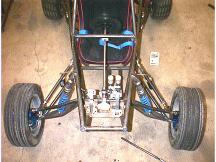 arm. Instead of having a single piece, I switched to a two piece design. This allows for very quick and easy adjustment without having to take anything apart. I set up the spindles in a jig that attached to the rear hubs and located them sixty seven inches (on axle centers) from the rear end. I now had my wheel base set. I then made sure that they were perfectly vertical in both camber and caster and built the front arms of the upper a-arms. This time, I only did four arms instead of six (still don't know what I was thinking.) After putting the this part on, I once again made sure the spindles were still in the correct position and then I made the back leg of the upper arms. This method put the top of the spindles right where they needed to be.
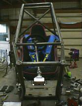
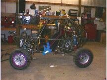
 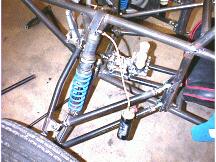 I followed that up by making the back leg of the lower arms and tack welded them to the front arm while still on the car. Everything worked out perfectly. It took a bit of time because I had to go through and disassemble each arm and then reassemble the new arm, but the results were perfect. I now have two complete pair of upper and lower a-arms ready to bolt in. All I need to do to finish the front suspension is modify the area in the spindles for the tie rods (open them up so there's enough clearance). It is really cool to sit in the car and actually see front wheels and be able to rock the chassis and feel it react. I'm fired up and actually beginning to see the light at the end of the tunnel - I may actually have this thing finished by the middle of October.
Right now the shocks are undersprung and need more damping, but that's a pretty easy fix. I need to pull them apart and map out the shim stacks and then adjust from there and I need to get hold of some stiffer springs. Shouldn't pose any sort of problems - then again, I have to call Axis to get the parts (eek!)
I still had to finish the steering on the front end. I needed to install the tie rods. I picked the front of the car off the ground so that the wheels would turn nice and easily and then set them at full right lock. Next, I installed a mock tie rod and turned the steering wheel to full right lock. What in the world? Why is the rack going the other way? It's at full LEFT! HUH? WHAT? Then it hit me. I had the rack in upside down for a leading arm spindle. Fortunately, I had it set up that I could install the rack with the input pinion either above (as it was) or below the bar that the steering mounting plate was welded to. Whew! Dodged a HUGE bullet on that one. I turned the rack over and everything lined up just fine.
I had to machine a new support for the steering shaft because by moving the rack from an upper to a lower position, as it changed the angle the wheel attached to the frame and it also raised it. By making a new mount, I was able to put the wheel back where it felt comfortable. I also had to machine a bit on the spindles where the heim joints attached. They were binding at full travel extension, so a bit of relief was in order.
I was so excited that I had a rolling chassis with steering that I wanted to take the car up the driveway and roll it back into the shop. Luckily, I remembered that I don't have the brakes done yet! Crash the car before it's even finished - that would have been ugly!
(10/7/99)
Rear Axles are IN!
I'm really impressed with Sway-A-Way. They came through great on my axles. On time, correct as ordered and to really put icing on the cake, they fit with no problems at all.
 When I set about making the model for the rear axle, I was a bit worried because at full extension of the rear suspension (hey, that rhymes!) the outer CV acted like it wanted to bind just a touch. I was more worried about it putting an odd load on the CV cup that comes out of the Pilot transmission. These cups are already known to break and I was really concerned that any odd side loading (due to the binding of the outer CV) could compound the problem. To make matters worse, at full extension, the inner CV's bearings were almost all the way to the outer edge of the CV cup - just more unneeded stress. But, I hoped that it was just the fact that the model axle wasn't quite straight and that the outer CV didn't have any lubricant in it. Turns out I was correct. (Whew!) I assembled the first axle and discovered that Sway-A-Way didn't quite get the Pilot end of the shaft quite right. The Pilot end of the shaft is supposed to be shouldered so the CV can only slip on a certain distance and then it's held in place with a circlip. But, for some reason, they cut straight splines so the CV could slip all the way past the spines and onto the shaft. A quick trip to the lathe to add another circlip notch so the CV couldn't slide and there it was - a finished axle.
As it turns out, my fears were put to rest. The straight axle and the addition of lubrication to the outer CV was all that was needed to make the whole system spin nice and smoothly. No binding, hitches or problems of any sort. To make things even better, as I spun the wheel and moved the suspension through its travel, the axle stayed quite a bit farther inside the inner CV than it did during the model's "dry run". Things are looking great!
return to table of contents (car building home page)
Return Home