


The Mini-Raptor Build 2018
|
2016 build 2017 build 2018 build 2019 build 2020 build 2021 build 2022 build 2023 build 2024 build 2025 build |
 |
 |
 |
 |
Jan 11, 2018
Trailing arms, bulkhead and jig are being picked up on Friday by Mr. Space-X for welding.
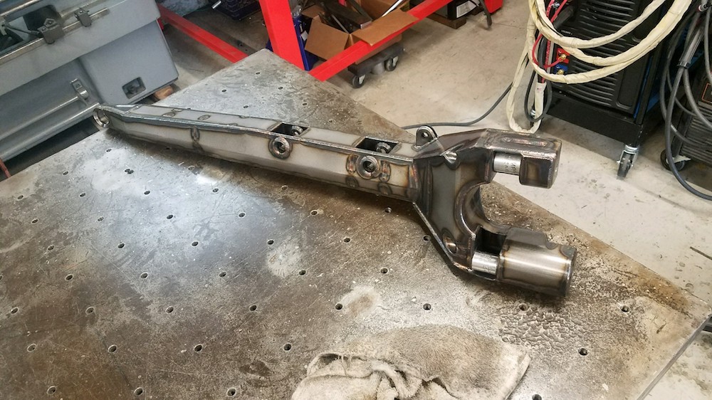
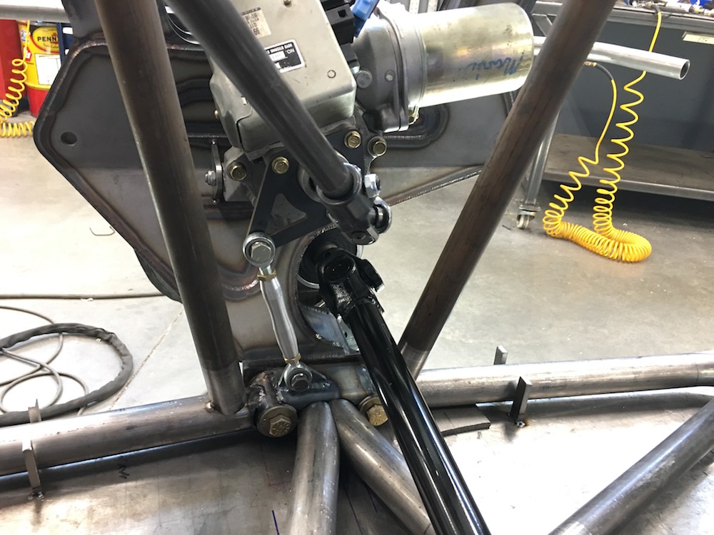
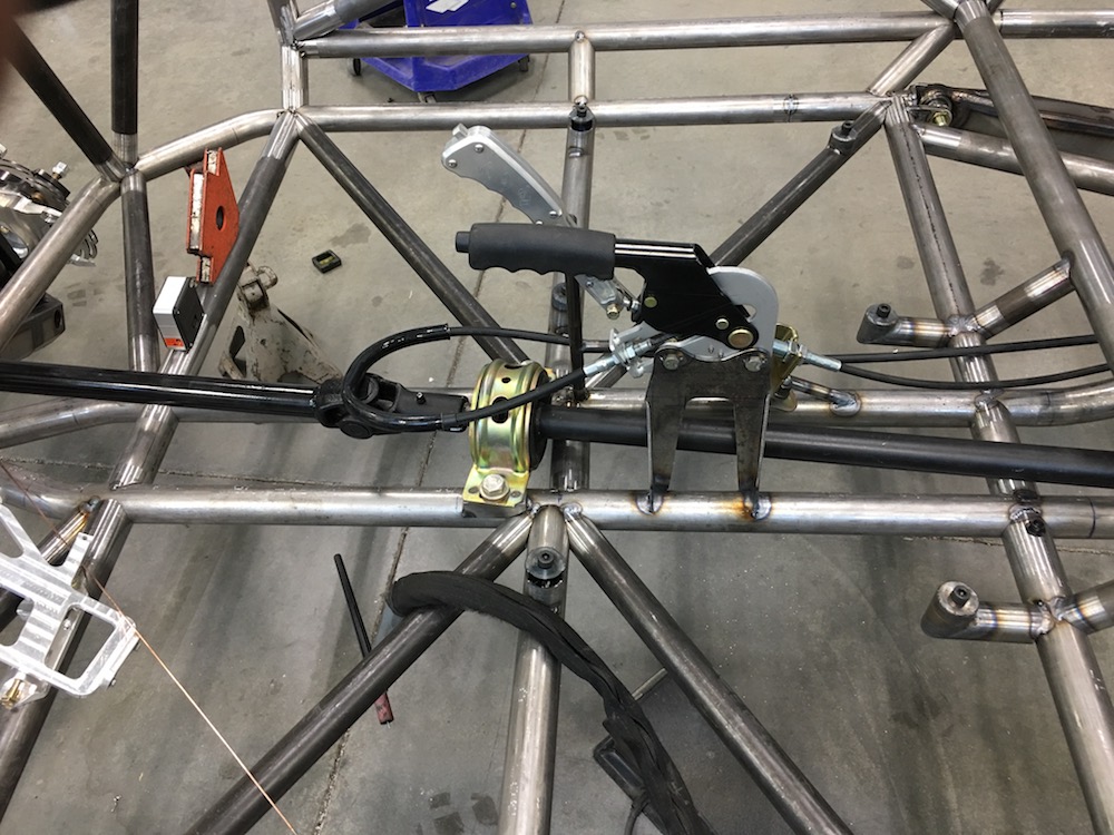
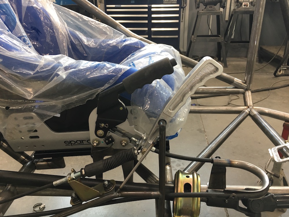
Power steering parts arrived and were fitted yesterday:
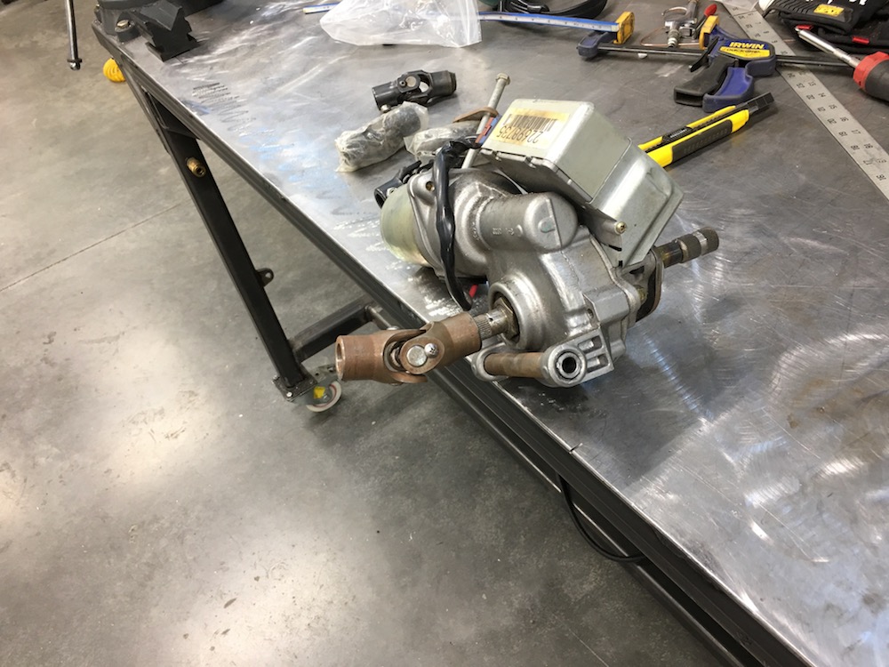
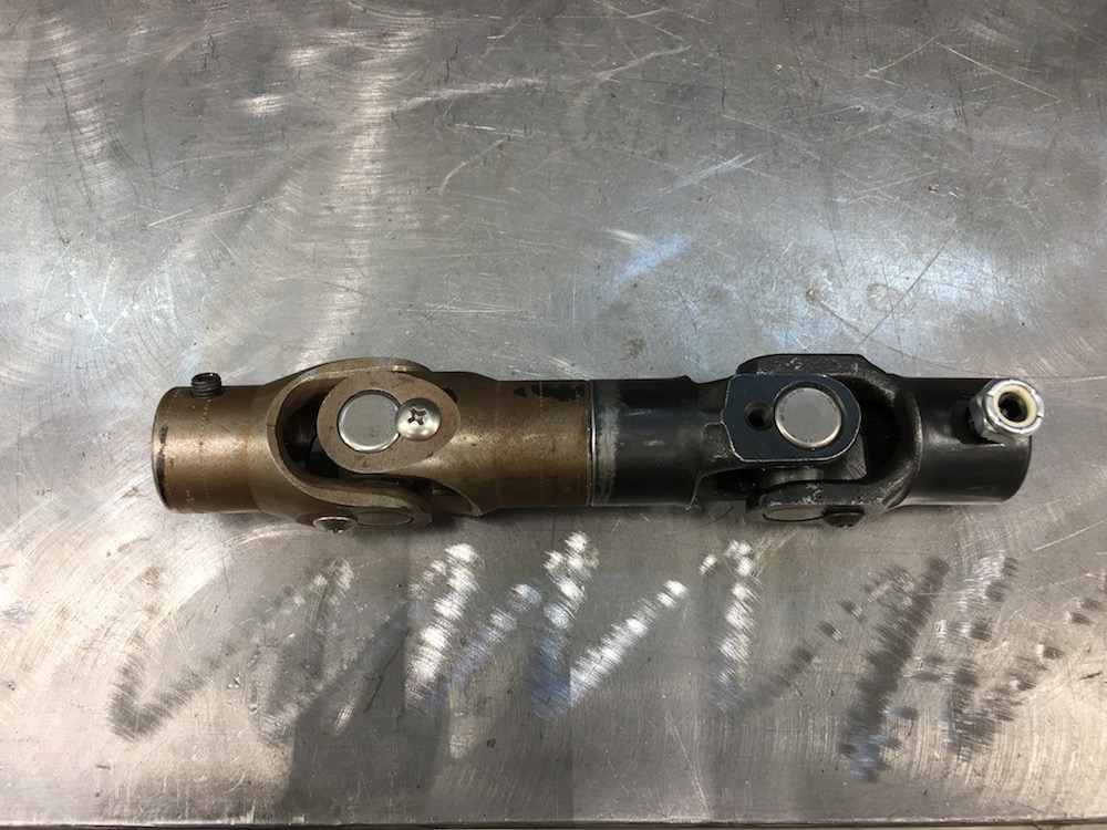
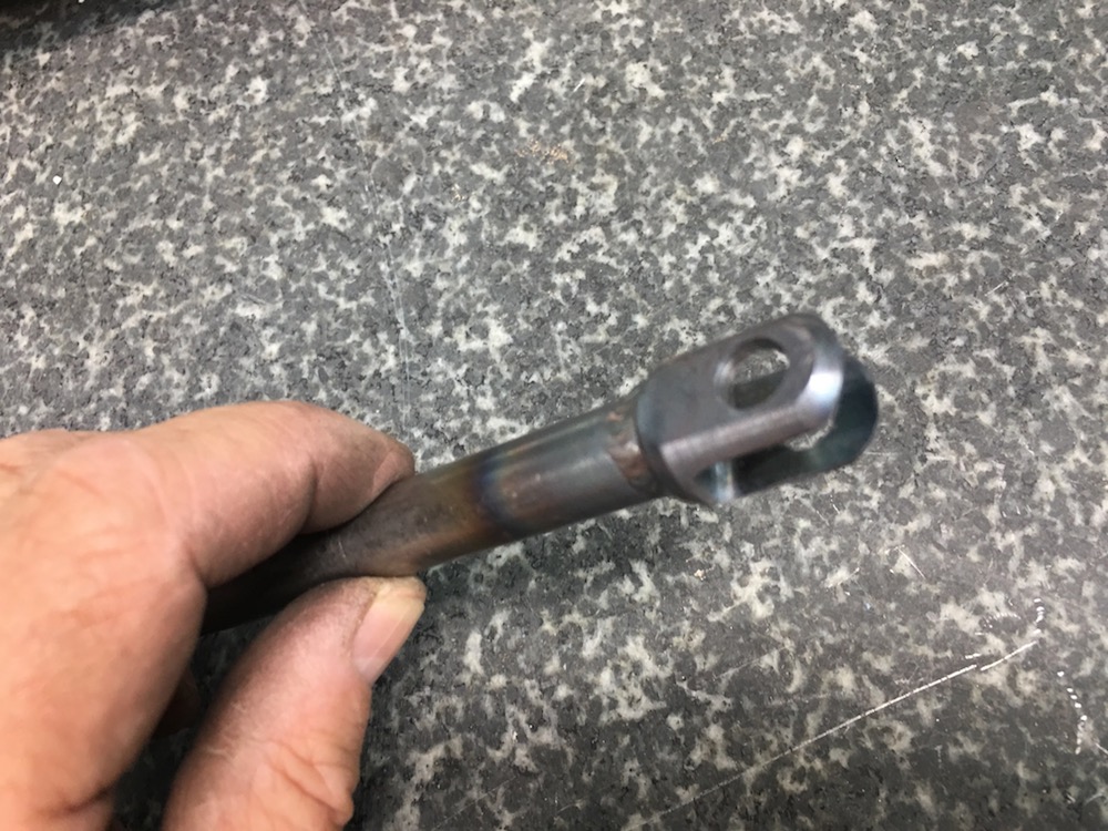
Power steering to rack u-joints clocked and almost ready for welding - still need to bevel the edges. Turned out that they fit between the two components perfectly. (good job designing Justin!)
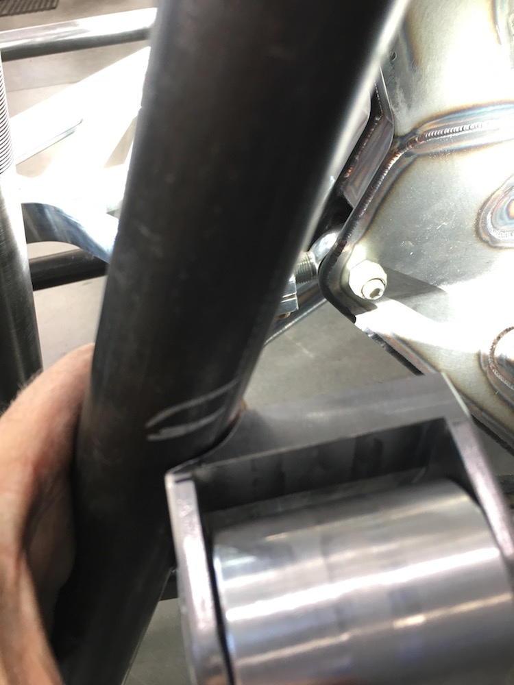
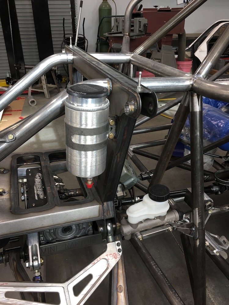
P/S on the bulkhead. I still need to figure out a stay for it. It presently pivots about the long bolt sticking out on the left.

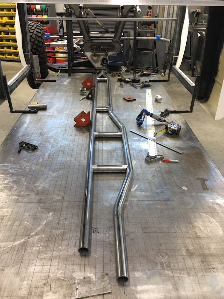
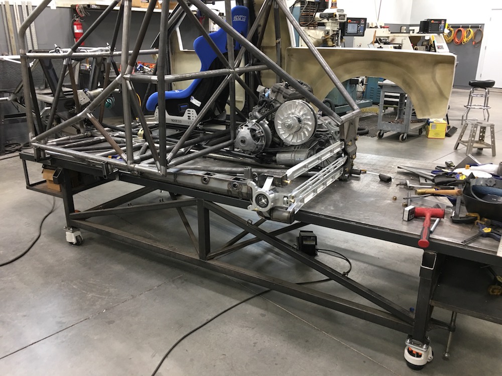
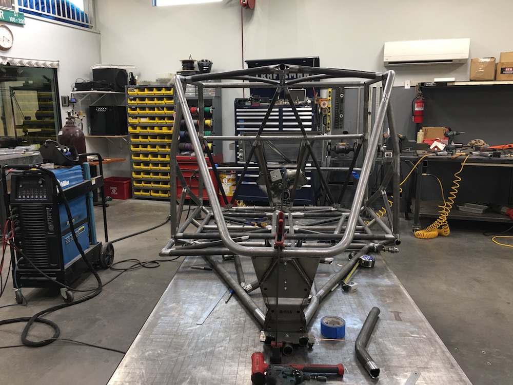
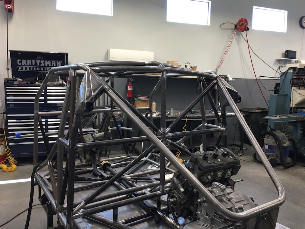
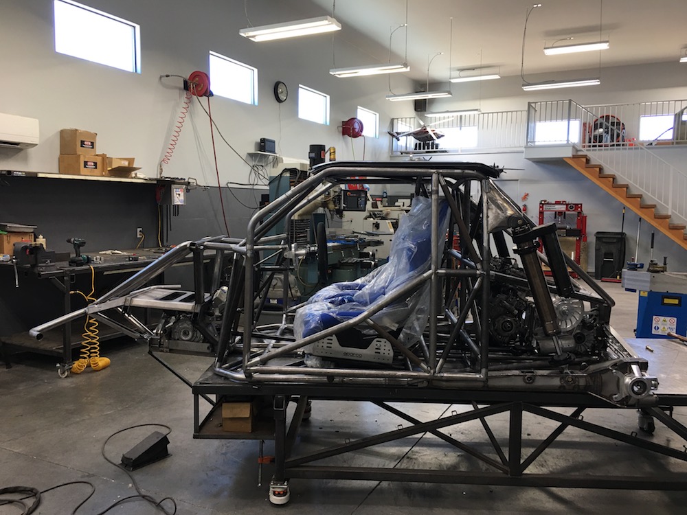
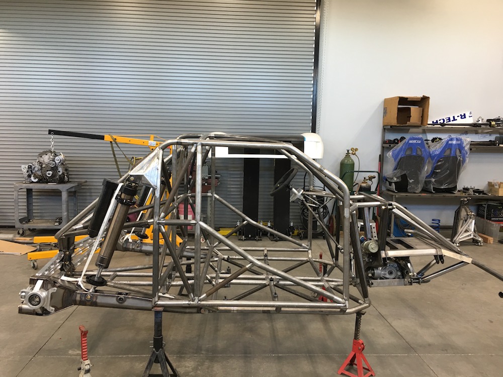
Chassis has started.
Jan 12, 2018
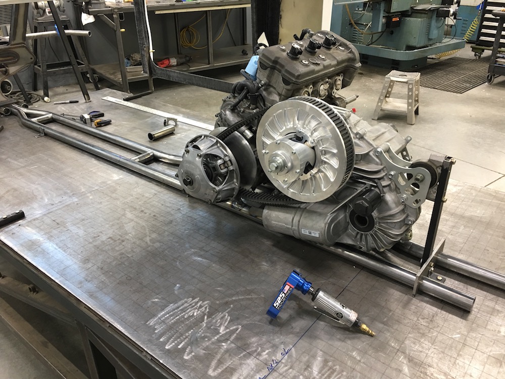
Got the lower tubes laid out and a couple tabs bolted to the table to hold it all down and jigged. My engine cradle dropped right on (whew).
The front end is getting the Ragnar setup so I can get to the a-arm bolts.

Trailing arms are done from laser and Mr. Space-X will be picking them up on Monday and starting his welding magic.
Shameless plug for 525 Industries 360 Tube Prep Sander. Getcha one!
Jan 19, 2018
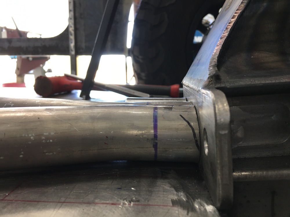
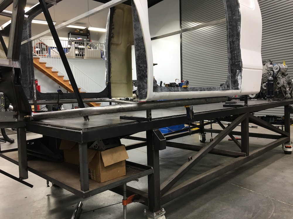
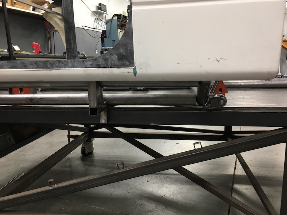
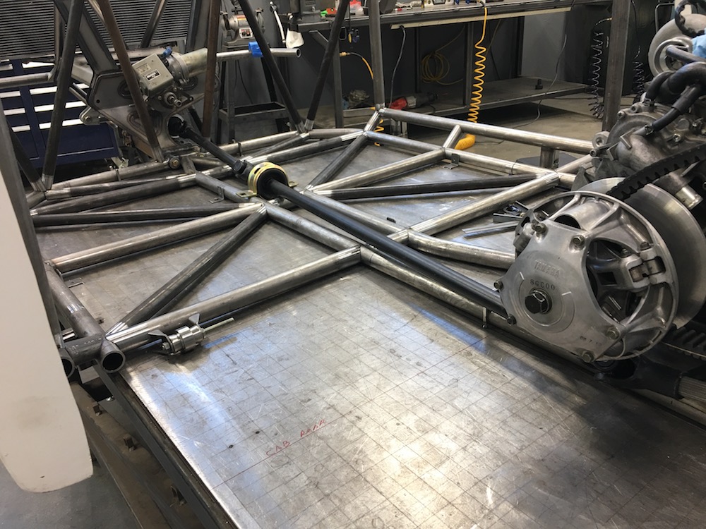
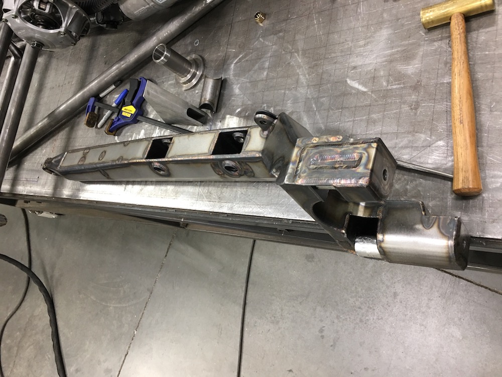
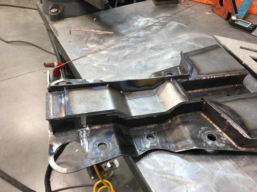
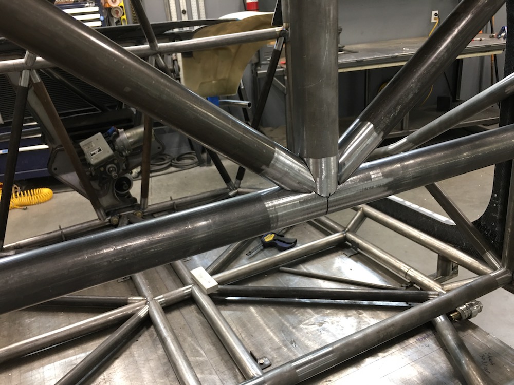
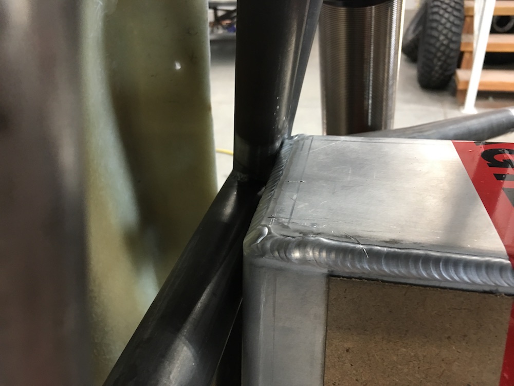
Main lower frame rails and the access bolt tubes fit in place. 1.50x.120 DOM now. Much better:
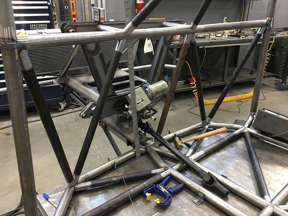
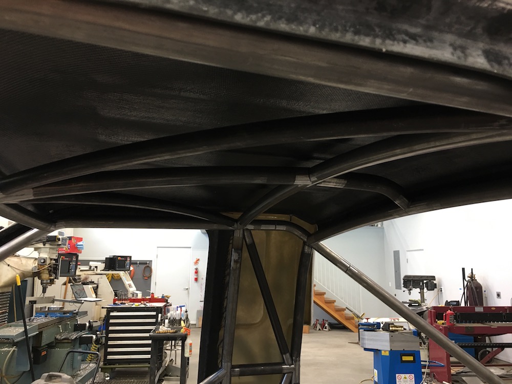
I'm machining most junctions/joints and such now. My coping grinder at the belt yesterday and so I switched over to doing it on the mill - no need for the grinder! The machined joints fit MUCH better:
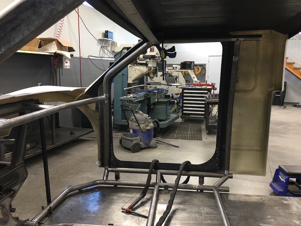
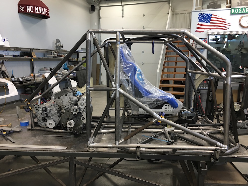
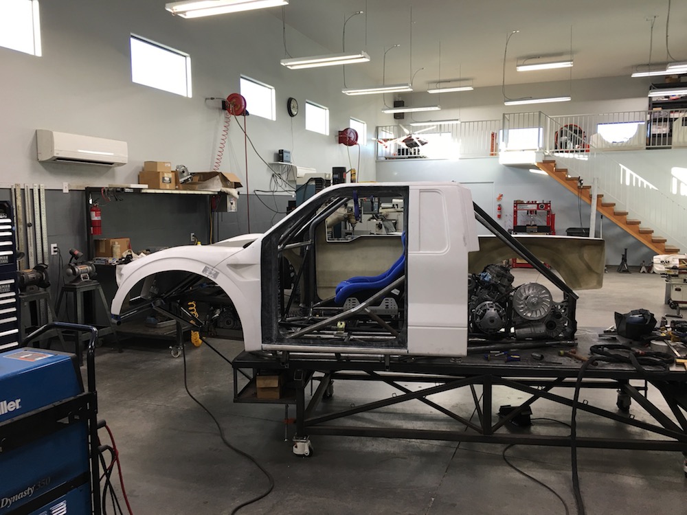
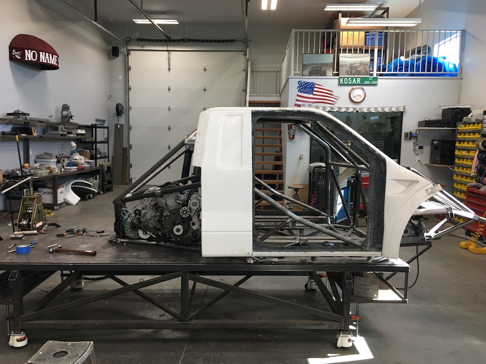
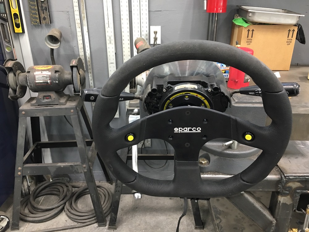
Test fit of the Sparco to see where it needs to be. I'm at a 4x4 and a 2x4 high, still have 5" of head room and can see over the hood:
Original idea to keep from looking like the cab has a body lift (it sits 4" above the table. I had enough room under the seat to go this direction but in the end decided 'nah, not gonna work this way either'. Besides that I get sick in boats and if this looks like a boat on the bottom, I'll be yaking out the window.
I was trying to tuck the lower outer tubes up against the bottom of the cab as best possible - then realized that I can't attach the rest of the cage to it. DOH. Rethink and redo time (along with LOTS and LOTS of text messaging among flyerrider, Bullnerd and myself - JD just played peanut gallery and watched).
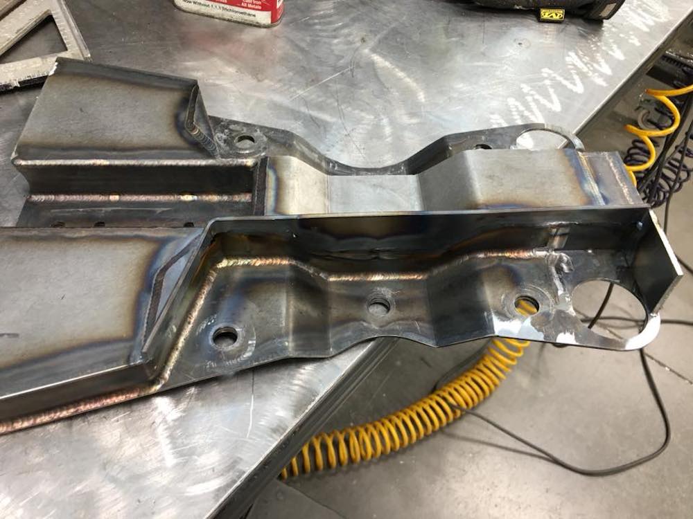
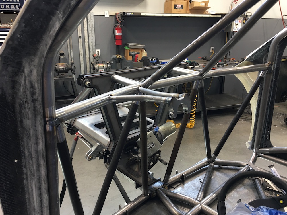
More bulkhead area fitment:
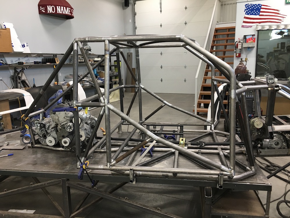
Time to get serious - ditched the boat bottom tubes and went with the body lift look - which in reality ended up not looking like a lift. I redid all four body jigs so I had clearance to get in and work. Turned out perfectly - actually got it located better than I had it. Tube on the right is angled inward to the required 48" wide lower section (need 48" for the width between the trailing arm mounts which are dictated by the fuel tank):
Test mock up of what it's going to look like from fore/aft. Miter cuts were a couple degrees off in this test:

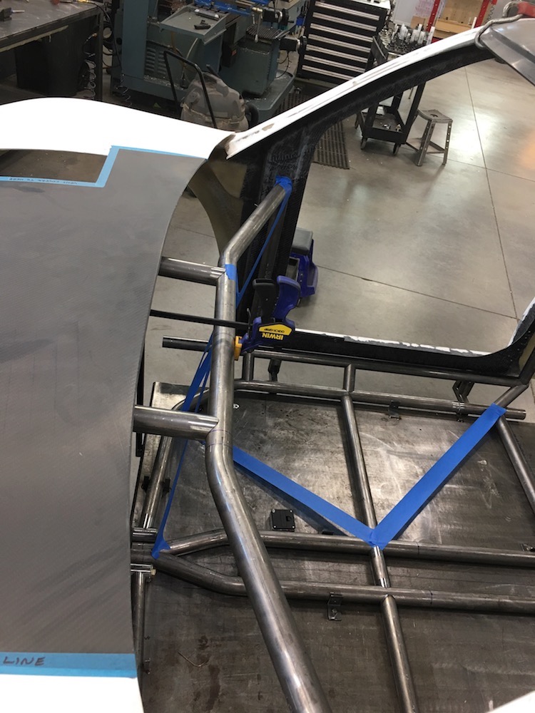
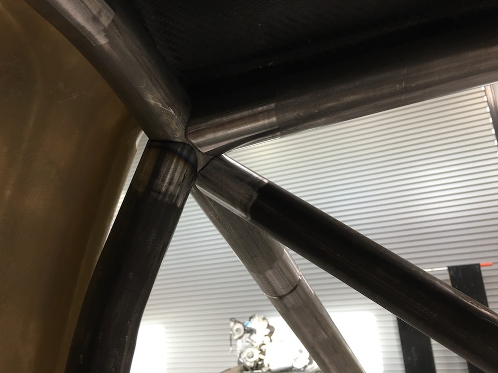
BendTech is BAD ASS!!! The B-pillar roll hoop fits absolutely PERFECTLY! Makes me happy that I didn't f&$% up a 124" long piece of tubing too. Originally I was thinking of having the tube right and behind the door opening but realized moving it back into the cab just a couple of inches made thins fit even better. I also got the front upper cross piece and the two lower A-pillar bars located. The blue tape represents 1.25x.062 bracing:
Top view of the front upper tubes:
Trailing arms ready for assembly by Mr. Space-X, the incredible welder. Yeah, I'm whoring out the really trick welding stuff...
Jan 21, 2018


Jan 25, 2018
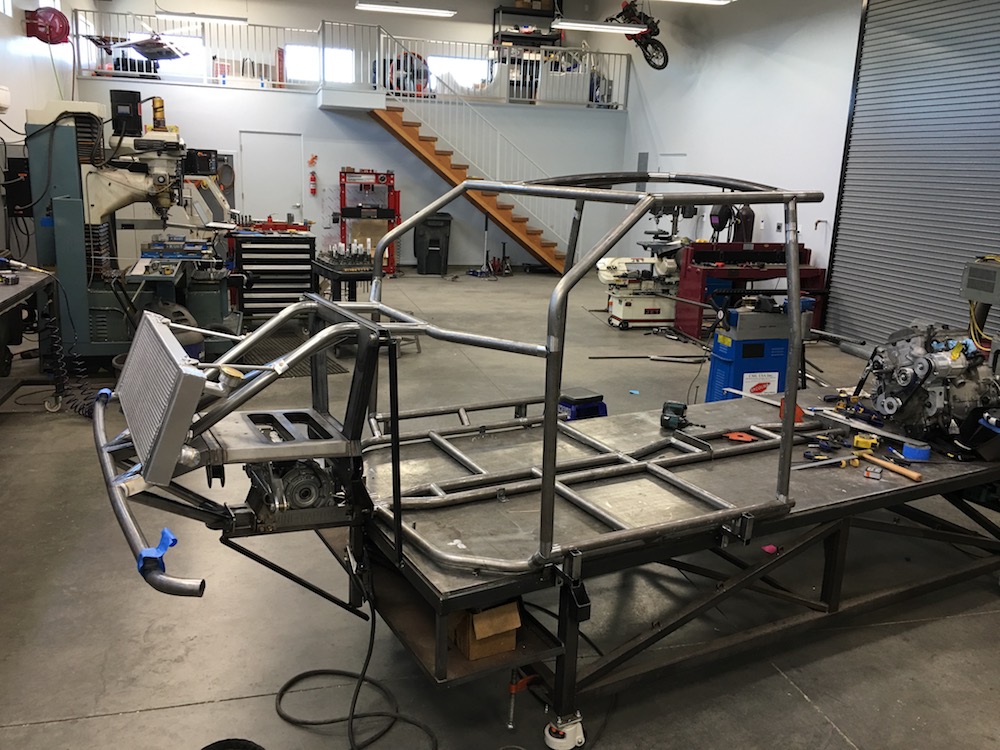
Front bracing (is done now). Clears all the vital stuff nicely. Whew.
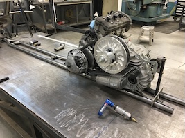
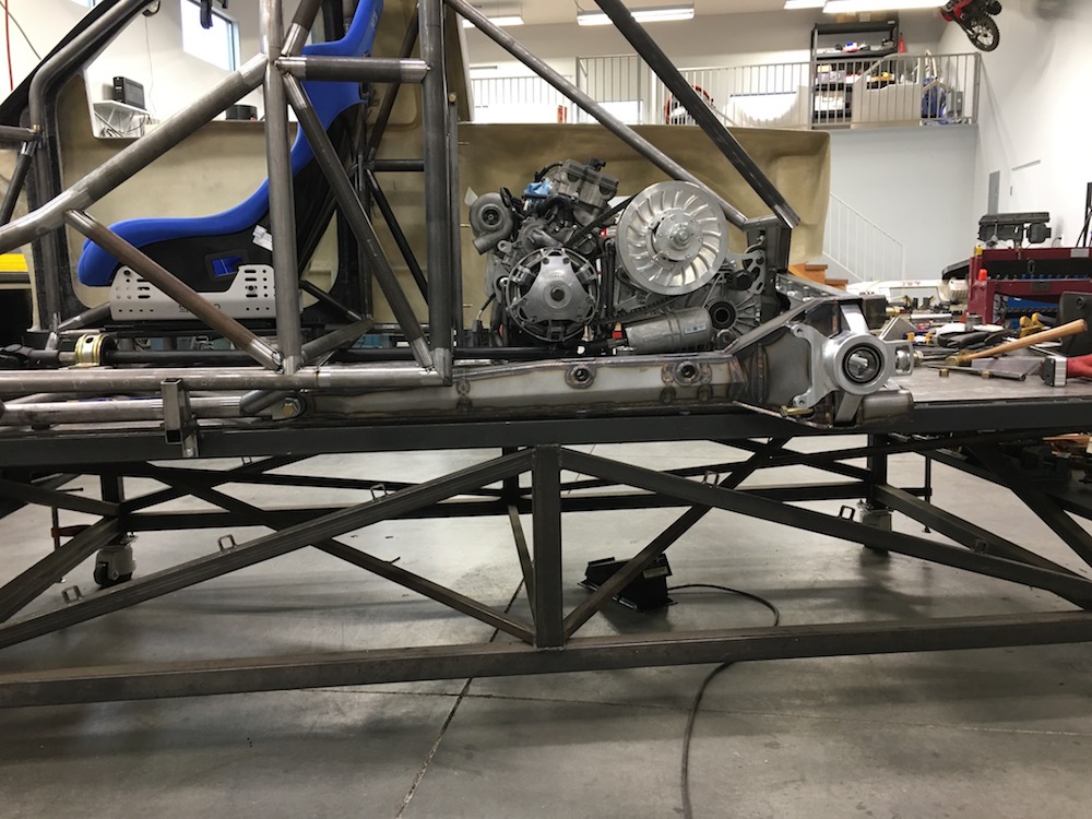
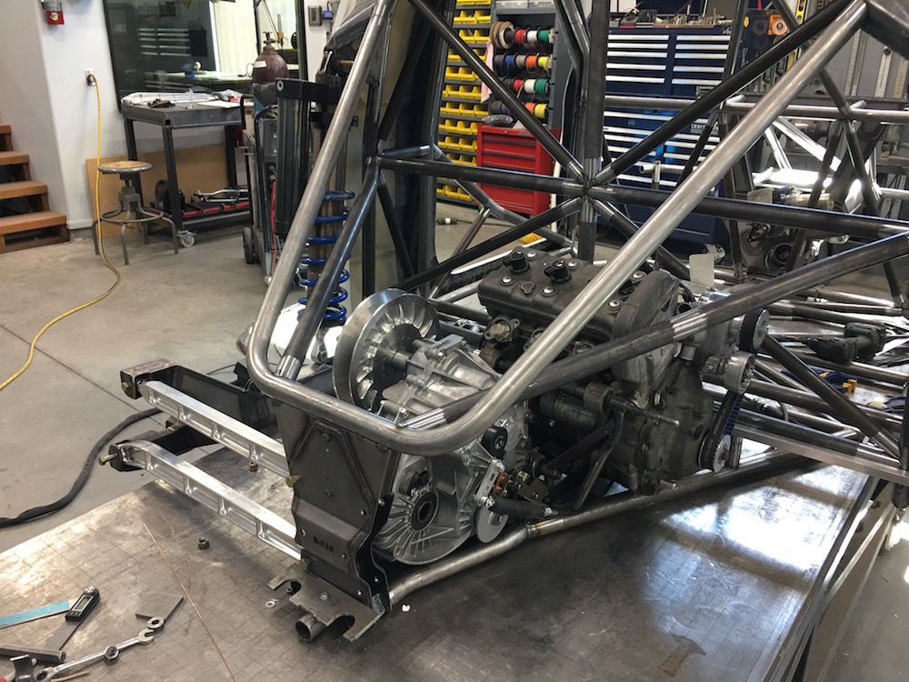
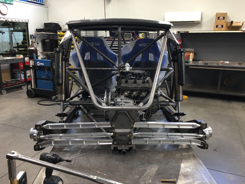
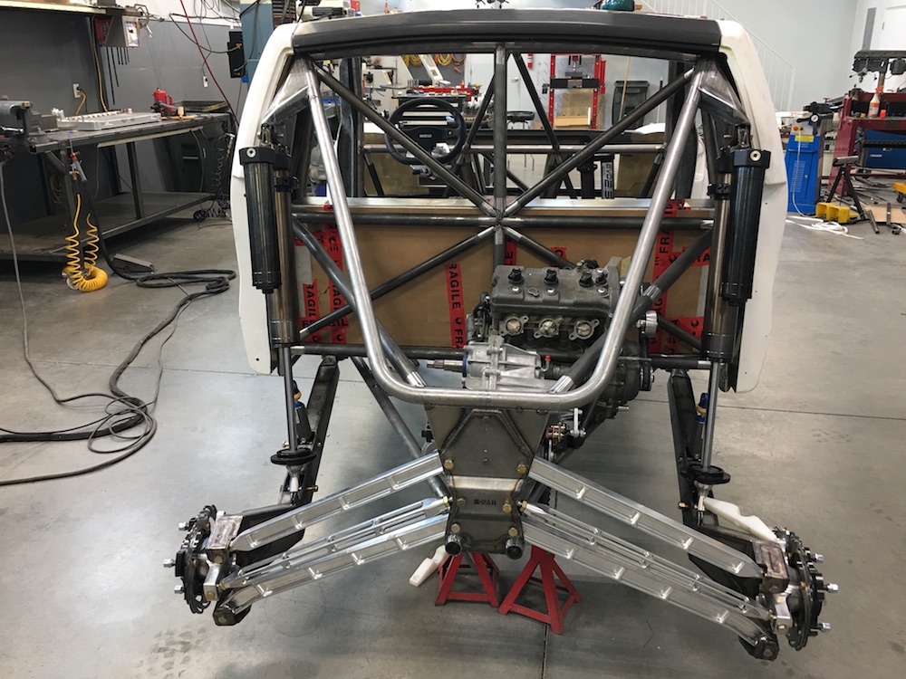
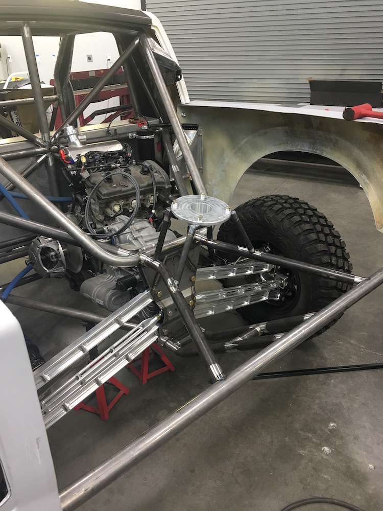
Fitment of stuff - engine in place.
Another shot of the power plant in it's home.
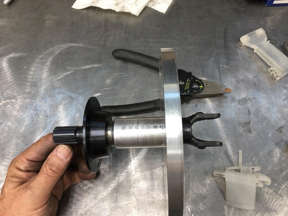
Front drive shaft fitment:
Of course it's short by this much. Crap.

But I'm going to lengthen the front one instead. The carrier fits perfectly here and the rear U-joint is in it's home now.
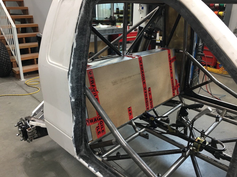
More test fitting - seat again, fuel tank from Talon, via Flyerrider.
Seat is purposely sitting about 2" too high momentarily.
Intake system clears the back of the tank - WOO HOO!
Jan 26, 2018
bdkw1
Nice, how big is the cell?
Me
About this big, by this big, by this tall - I'm holding my hands apart appropriately, you just can't see it.
If flyer would show up here on the forum every now and then he might be able to tell us.
Or maybe Talon can.
I got it second hand when flyer realized he wasn't going to continue with the Ragnar. It's a bad-ass tank too - nice internal baffles, quality sized pickup res in the bottom.
Talon knows what he's doing. Guess I need to pull out the garden hose and a couple of five gallons buckets. Or even better I could go do the math. I am an engineer, after all (or so that piece of paper says).
Anyone need a Jeep radiator with fans and a shroud just like the one I have on the Raptor? I inherited one with the fuel tank.
9" wide base
2" wide top
20" tall
44" wide
4,840 square inches
20.95 gallons.
WOO HOO!!! I have fuel range!
BOO HOO!!! That's a pricey tank when I wanna run race fuel and have 225 hp. I see the 180 hp and 92 octane setup being used more often.
Jan 29, 2018
Side bar fitment:
Da udder side:
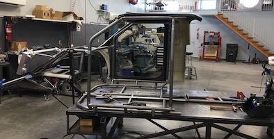
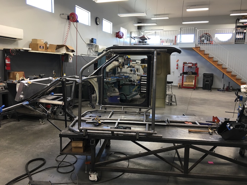
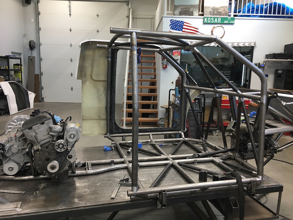
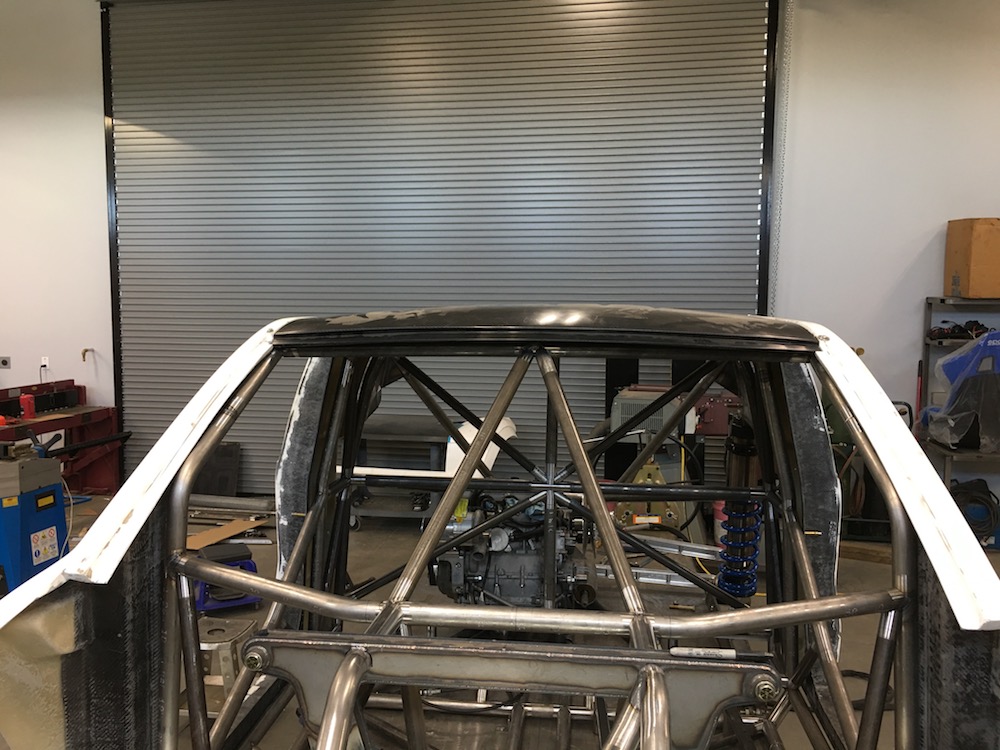
Looks like a cab now!
Roof bars done:
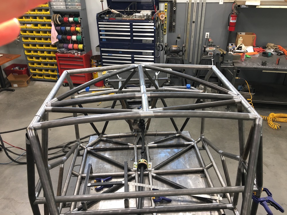
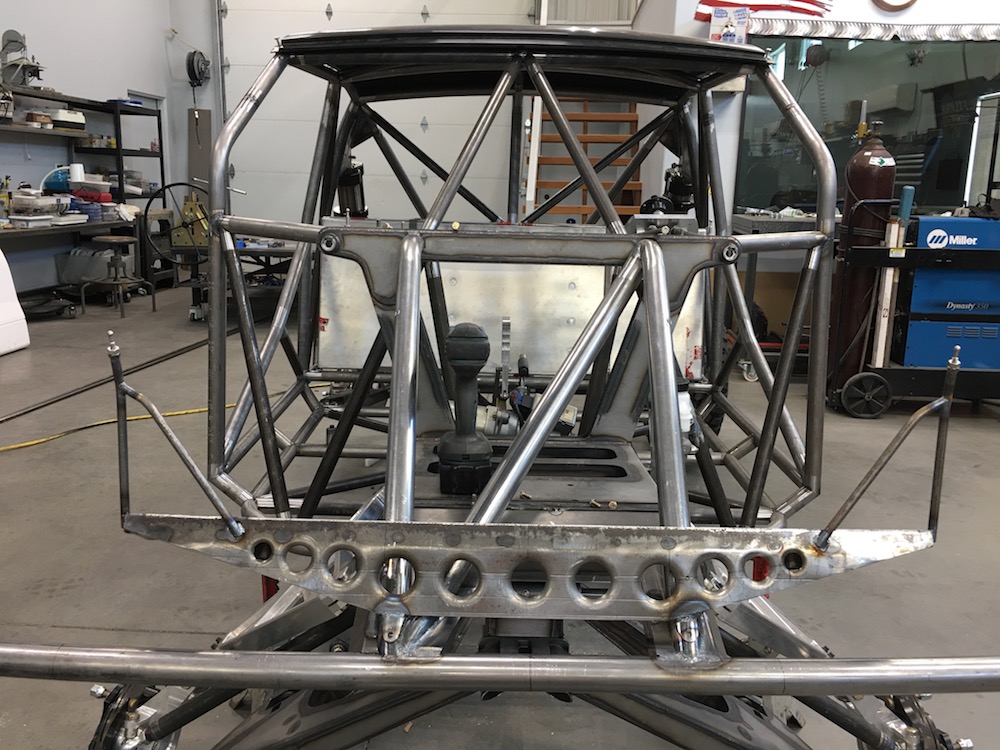
Now I need to start tying in the bottom of the cab and the top of the main rails and then figure out how to put some bracing in around the engine without trapping it or making it semi-impossible to remove. I see a couple of Camburg Clamps getting used in here. Fortunately all the engine cradle/rear does is hold the engine in place. All the driving forces and suspension forces go into the back of the cab.
Feb 5, 2018
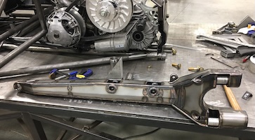
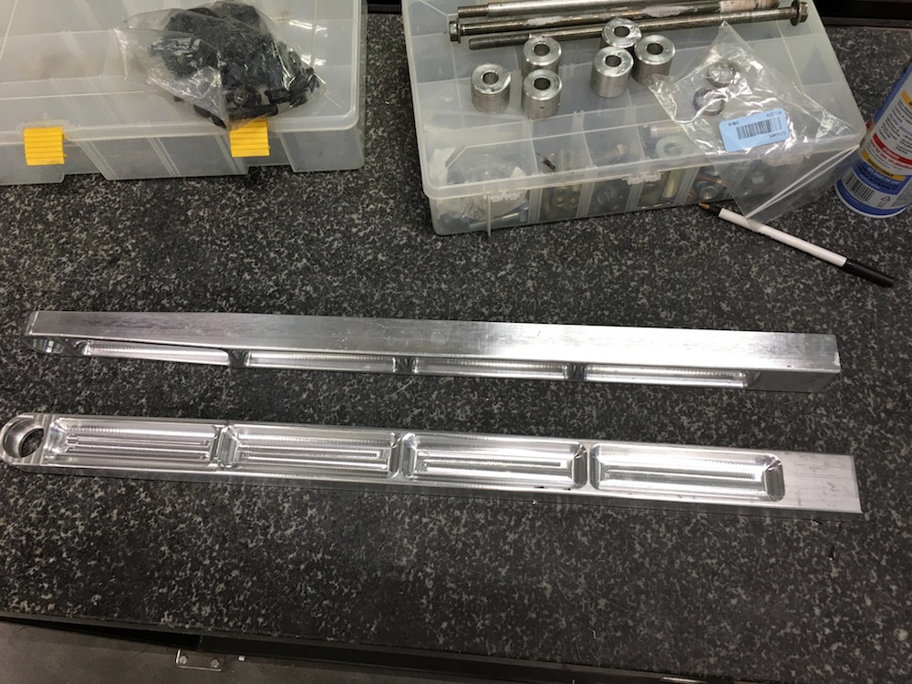
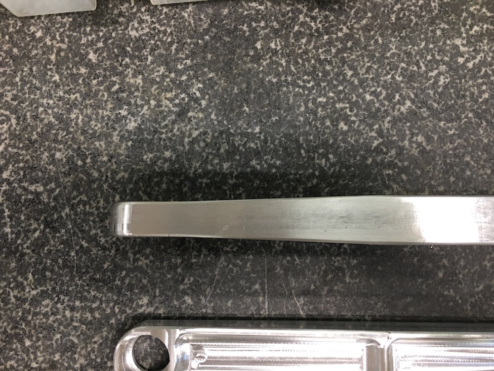
Trailing arm porn!
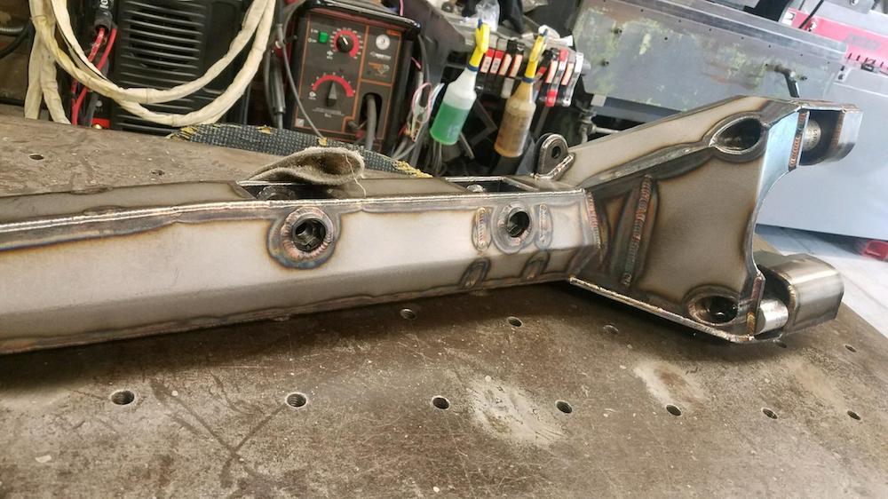
This arm and the rear bulkhead are supposed to be boxed and shipped today and the second arm will be on hold for a couple of weeks - Mr. Space-X is a busy guy.
I'll get the bulkhead in place and knock out the transverse links so I can place the suspension on the chassis. Next will be upper shock mounts - this is gonna be fun... More sheet metal work for JD.
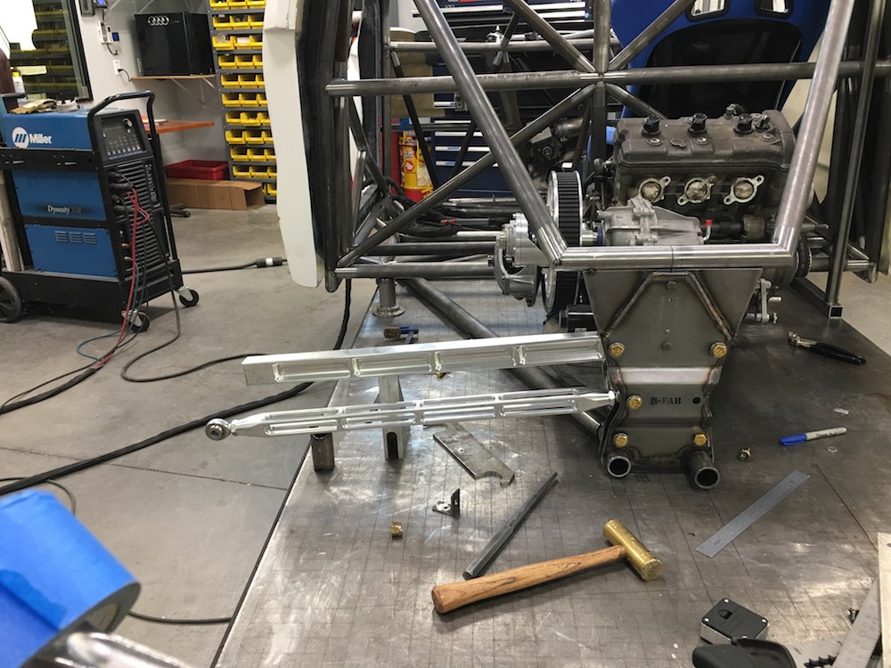
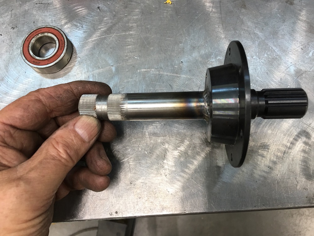
With the arm in place I'll be able to get my axles set up and on order with Benihana.
This thing's gonna be a roller soon!
-----------------
Hey, does anyone know where I can come up with 2" of LEFT HAND thread 10-32 rod or a bolt or sumptin? McMaster doesn't have it.
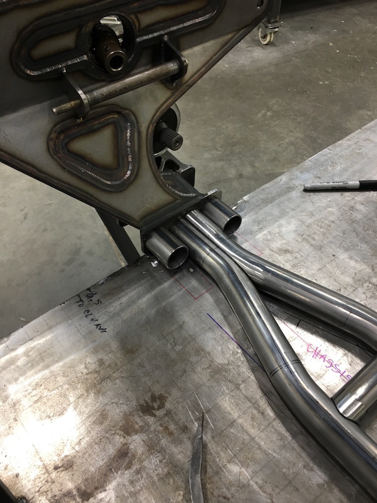
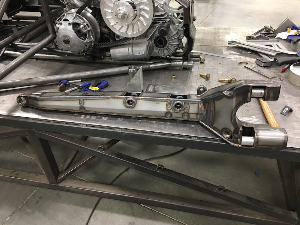
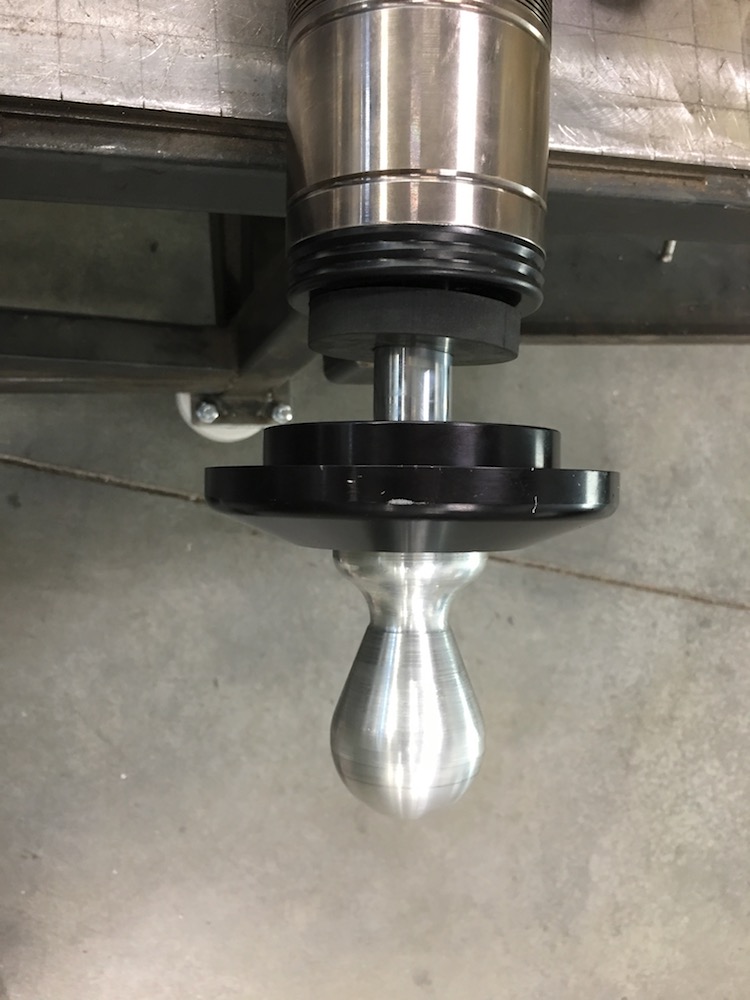
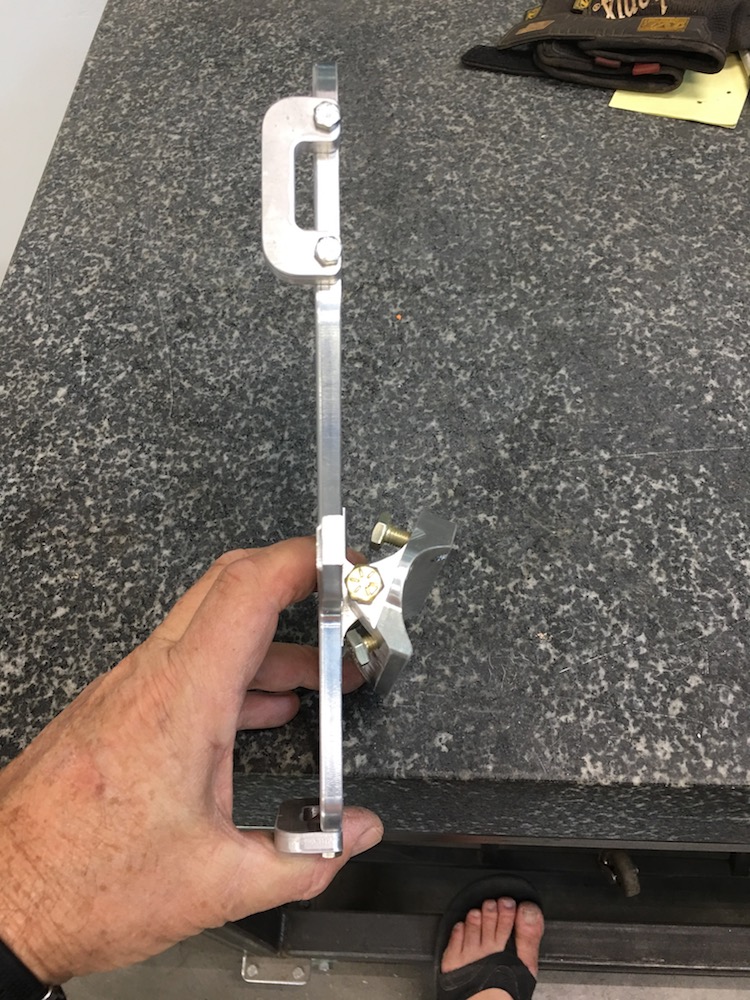
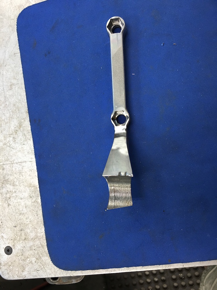
The trailing arm mounting had me baffled...
Been trying to visualize what to do...
While I was cutting braces and working in the area today I suddenly saw it in my mind's eye.
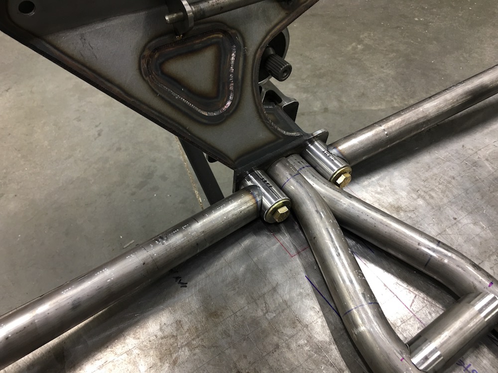
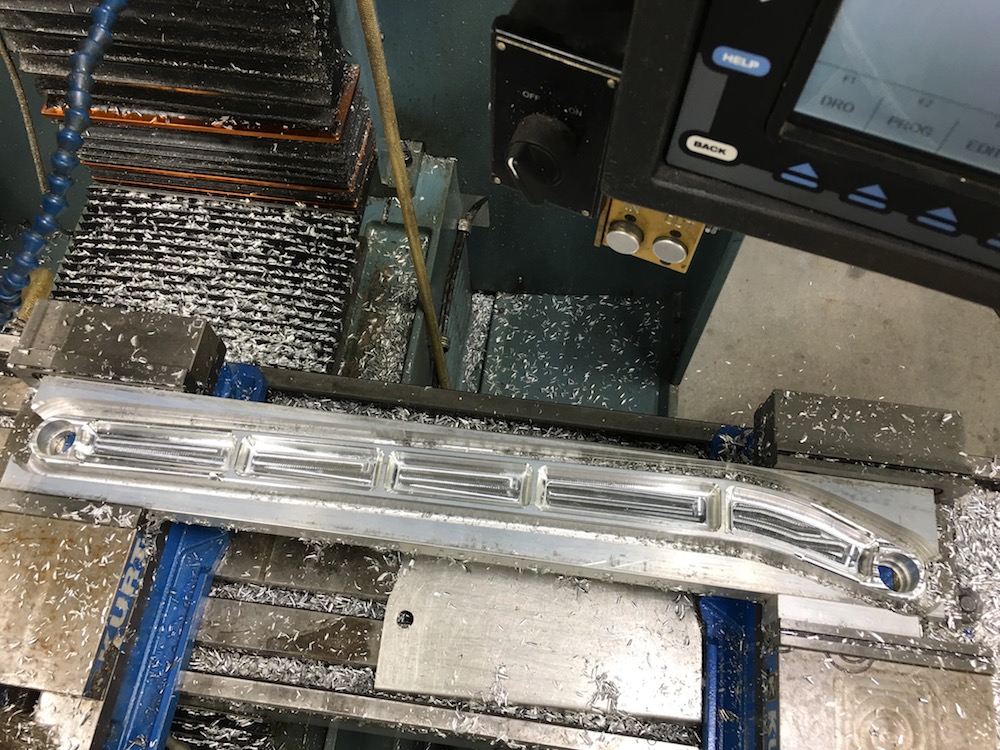
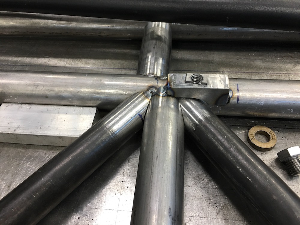
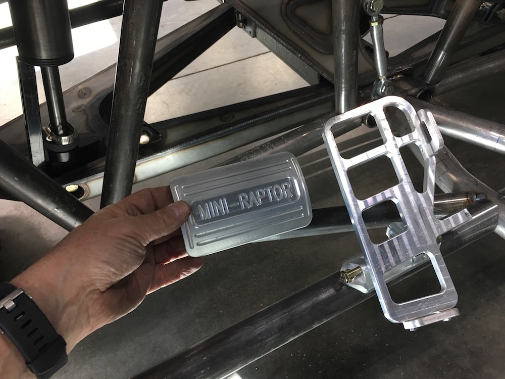
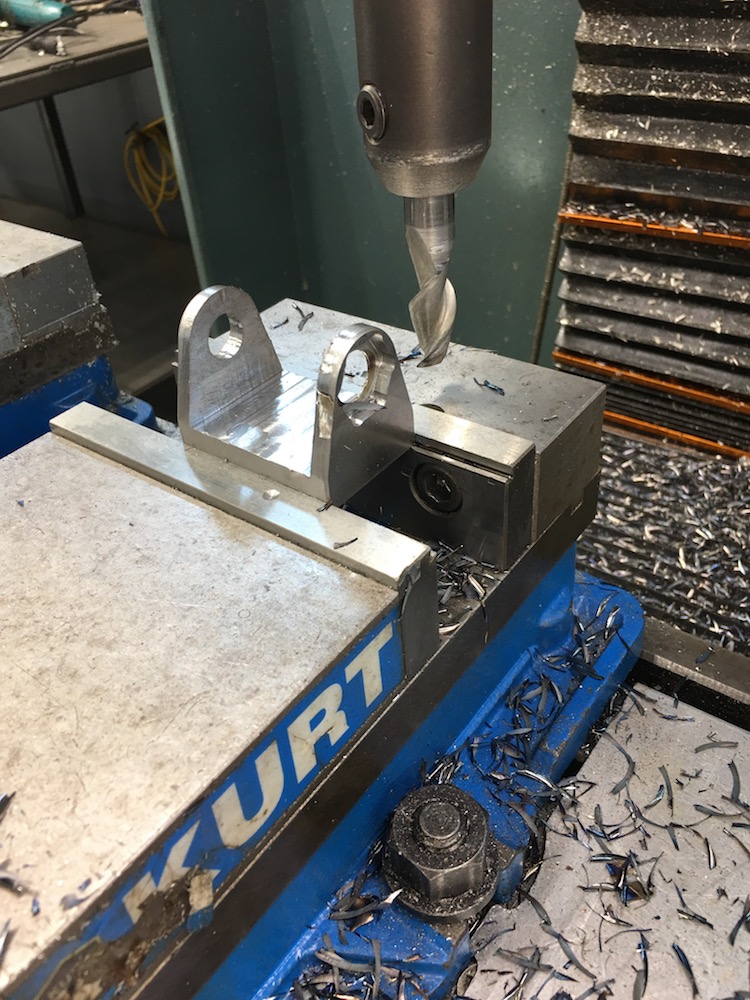
Billet time. The damn chips are HOT and I made thousands of them.
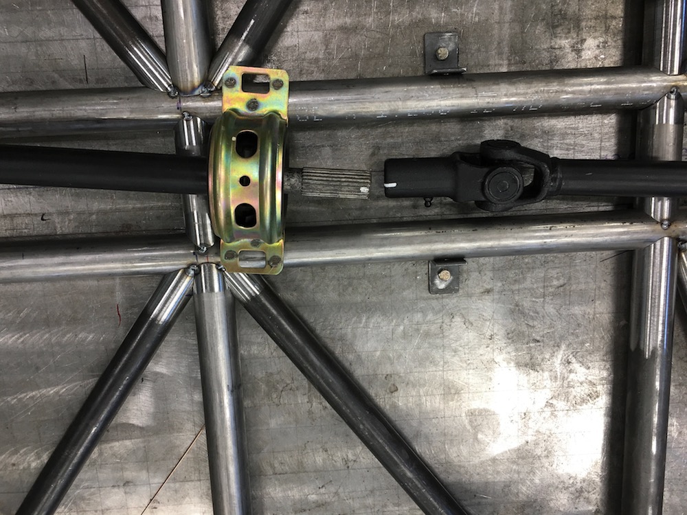
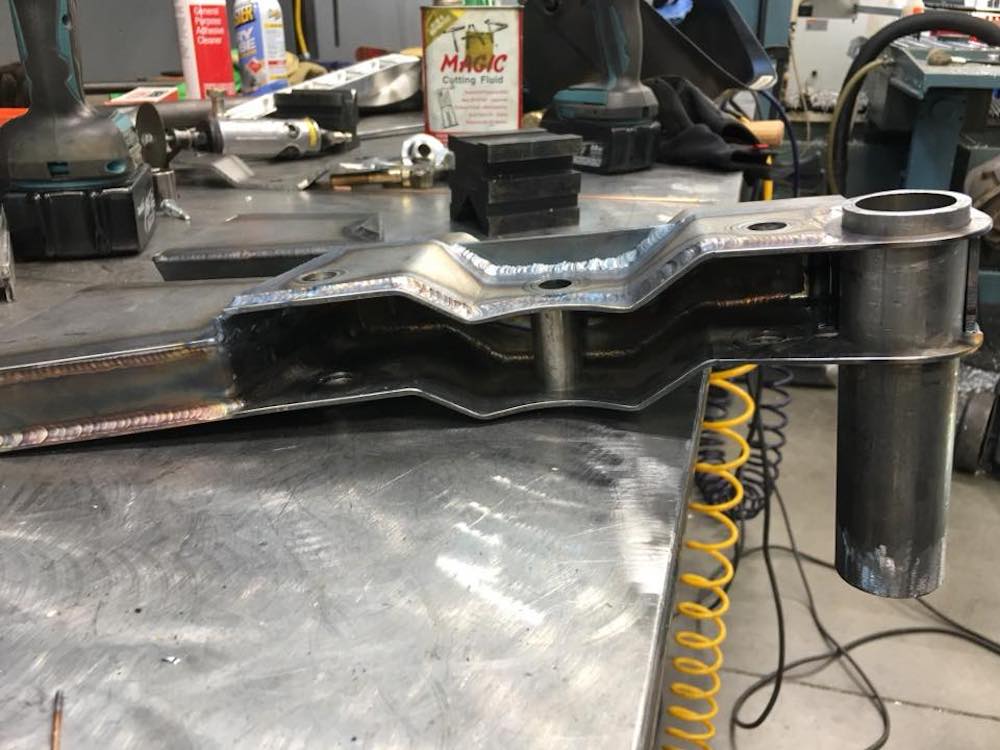
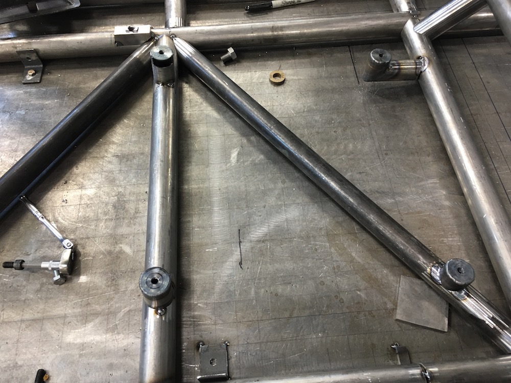
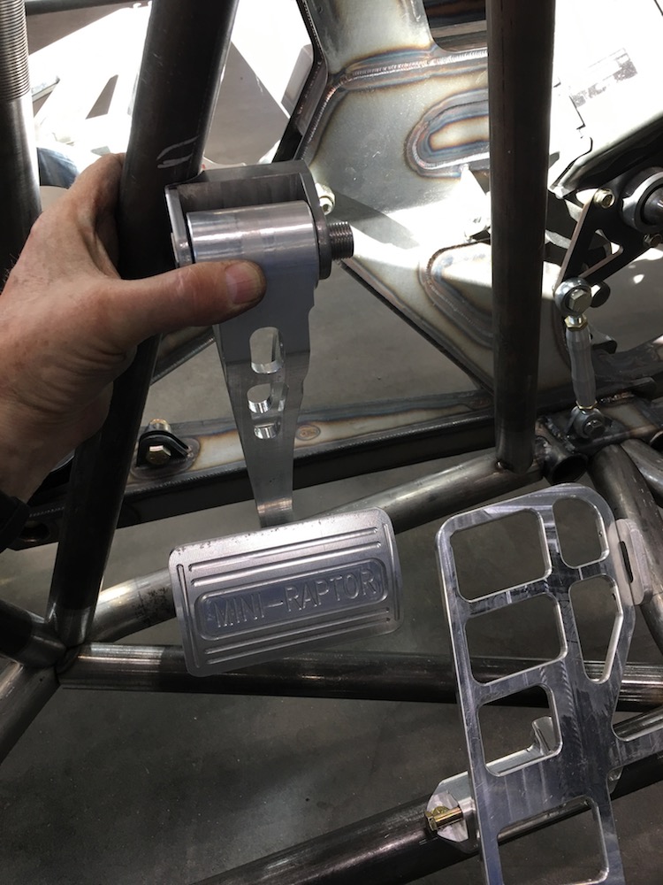
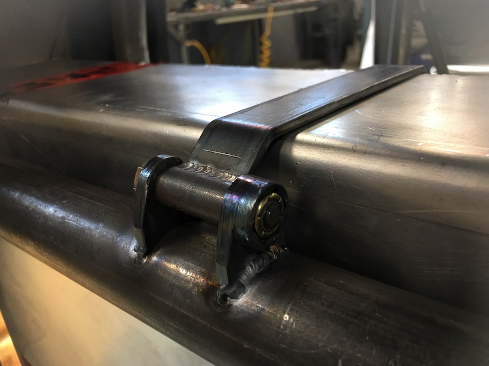
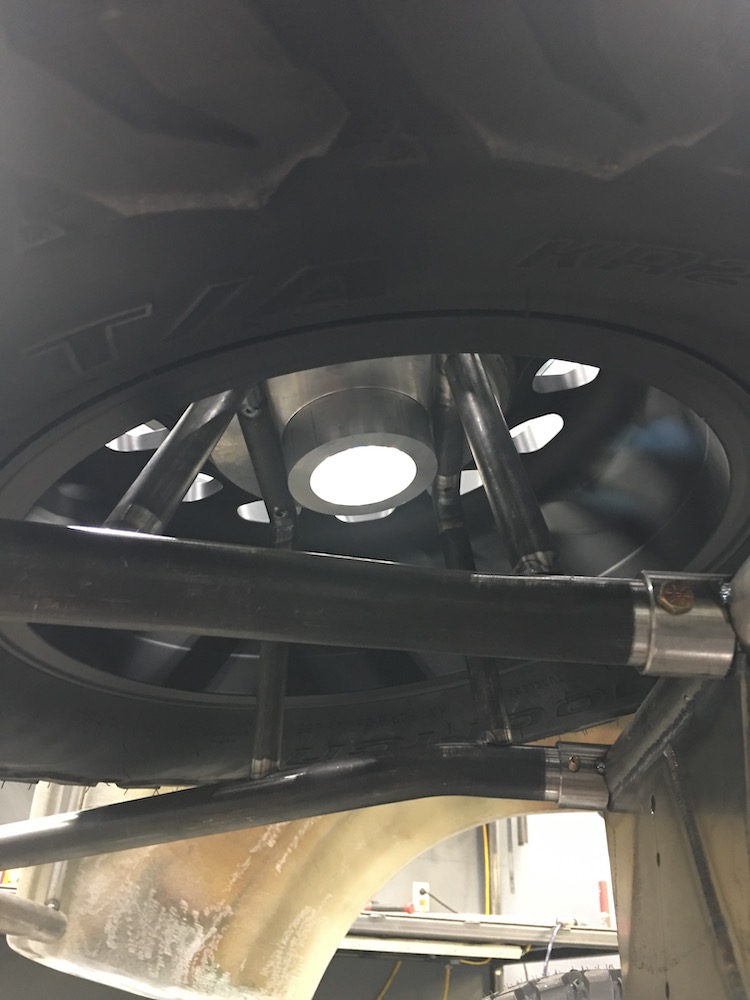
These plug into the back of the main chassis bars and place the trailing arm uni-balls where they're supposed to be in relation to the chassis.

Lots of material removed from a couple of 1.5 x 2 x 2.5" chunks of steel.
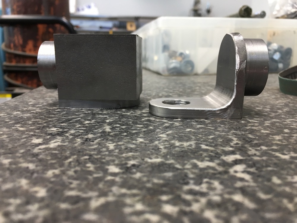
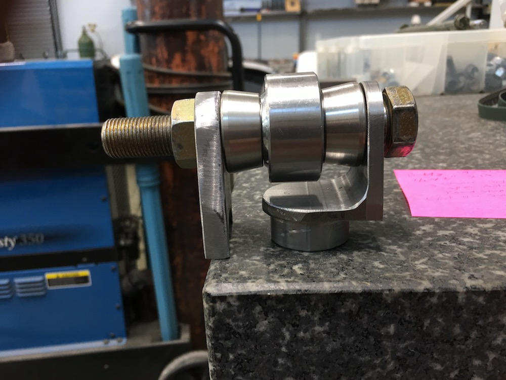
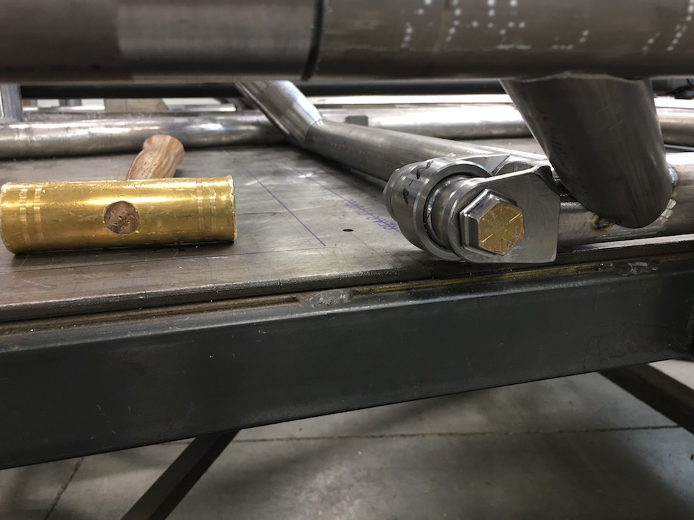
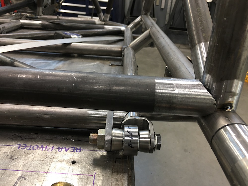
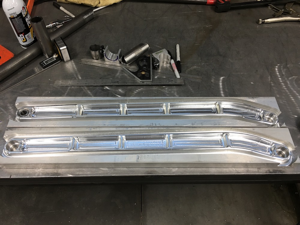
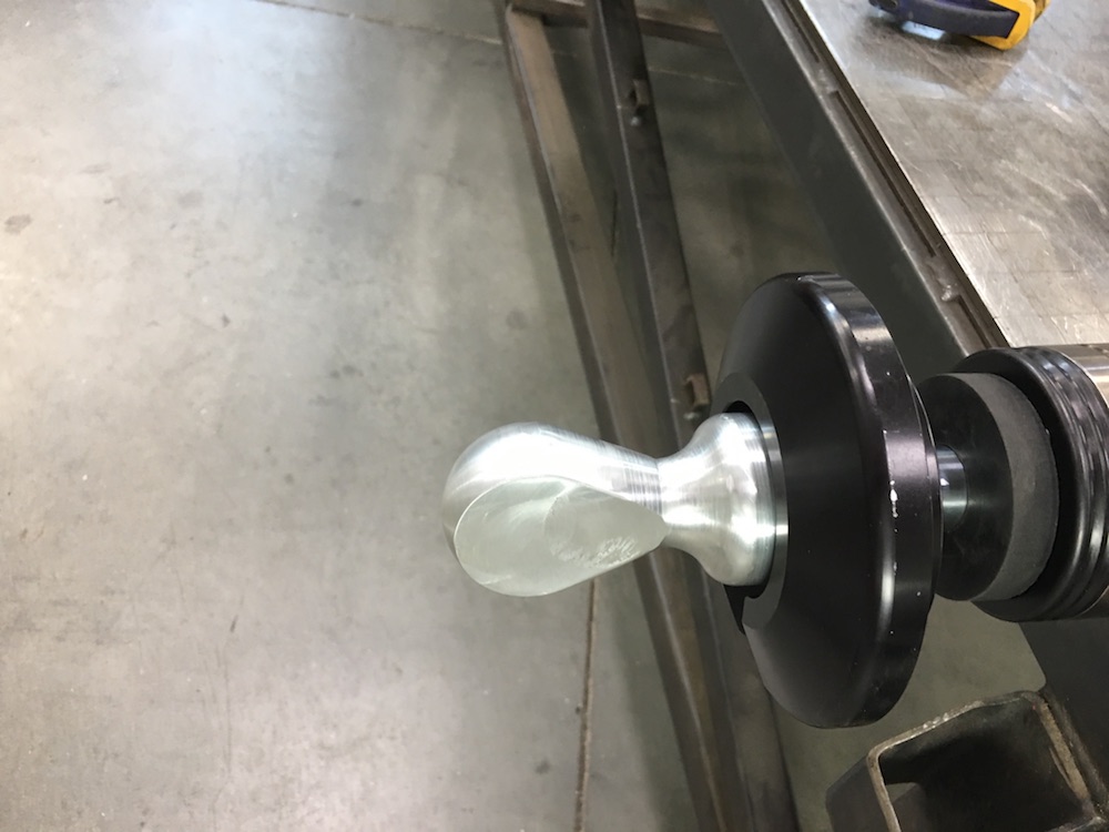
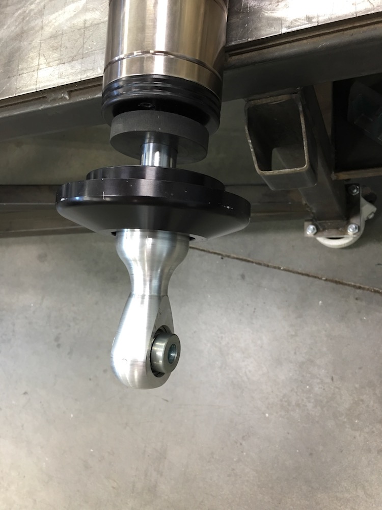
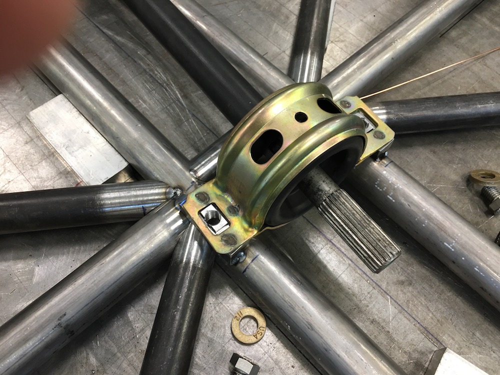
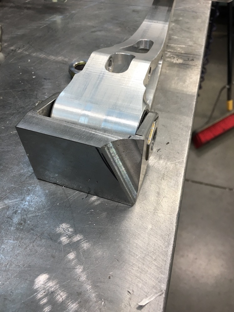
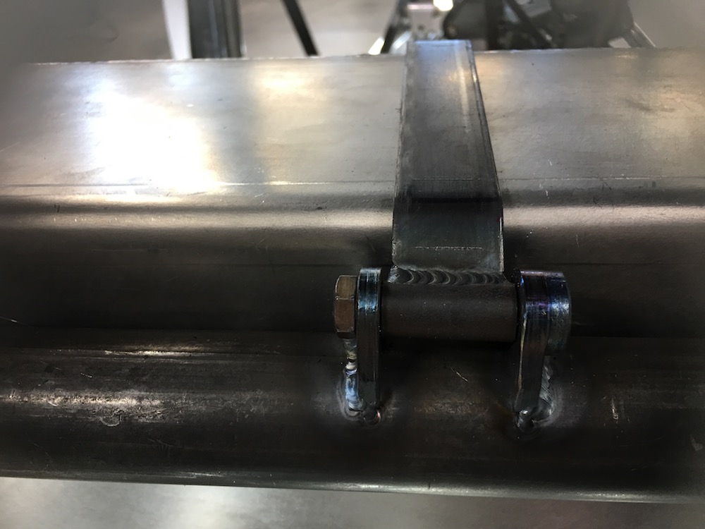
Uniball in place with the inside support plate:
Inside plate is .375" thick, has a nut pocket cut into it and a lightening window. Should be exceptionally stiff.
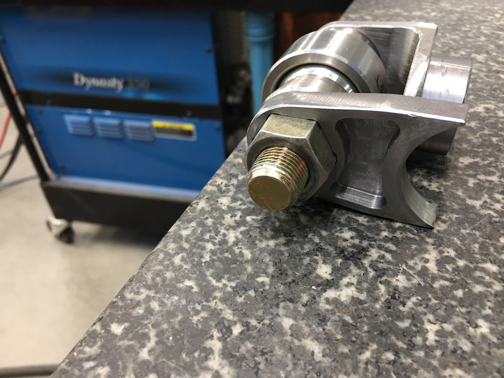
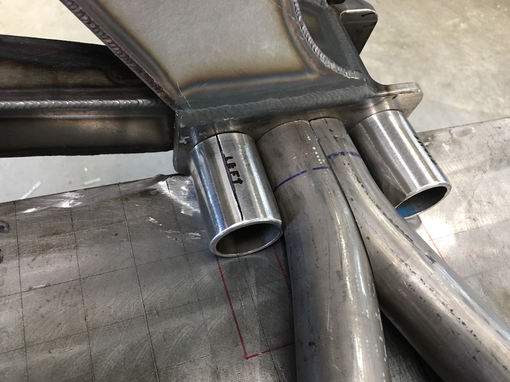
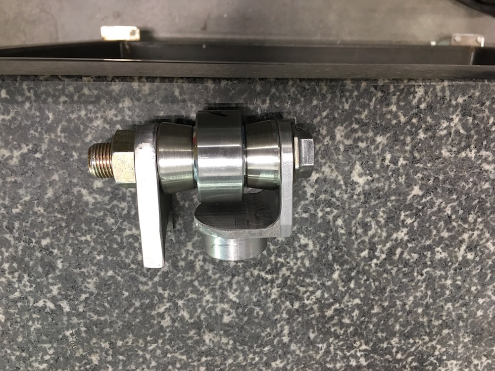
The assembly plugs into the back of the main chassis tube:
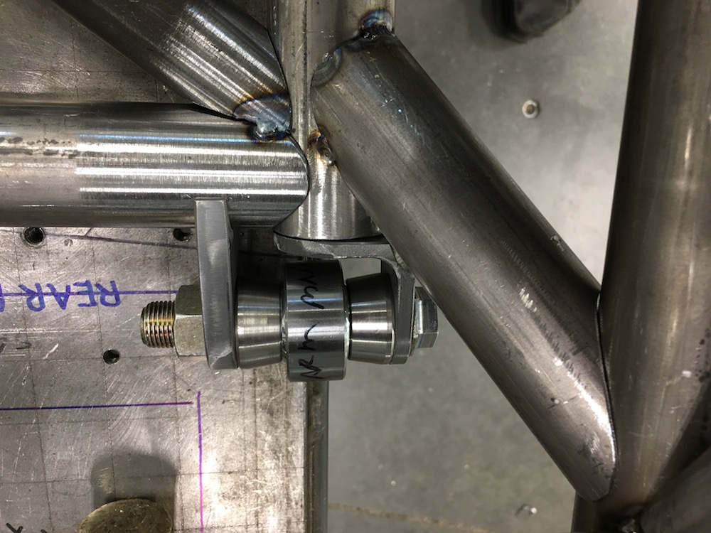

Here are the short braces in place between the back cage cross bars and the lower center section. I have two mock up tubes headed back to the center frame - they'll attach just in front of the trans.

It's been a good day!
Feb 8, 2018
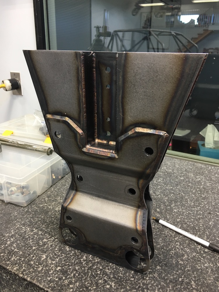
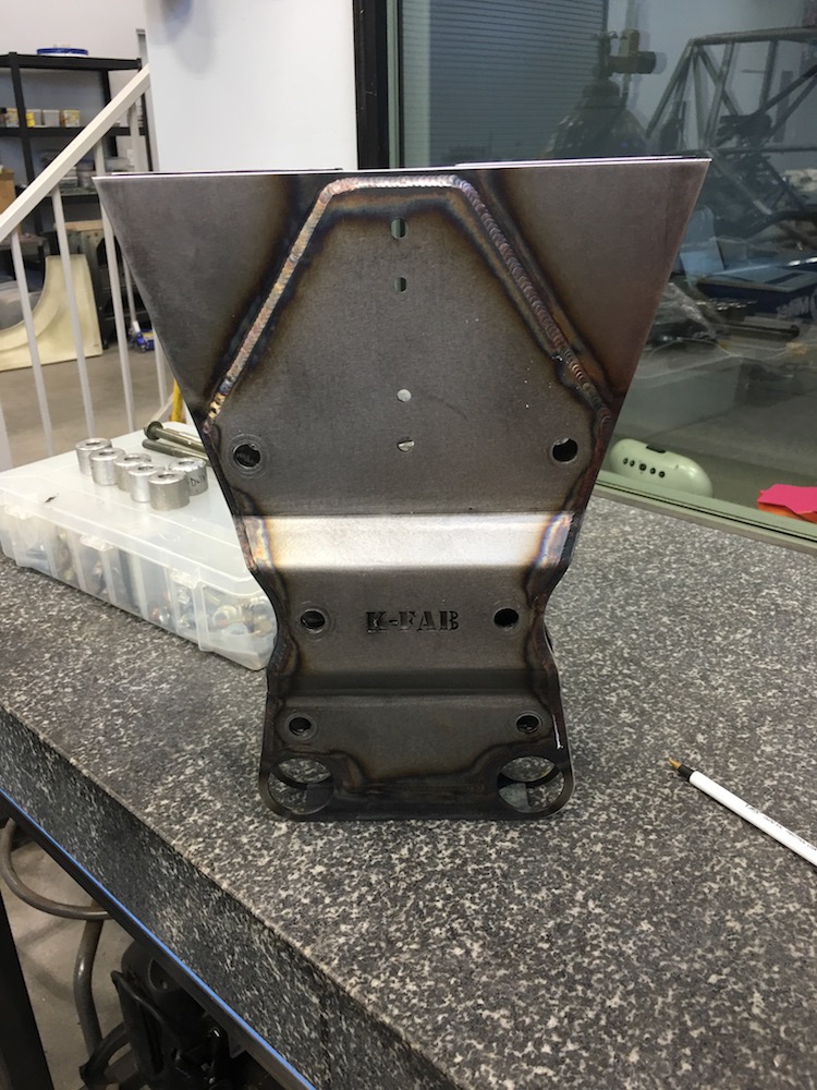
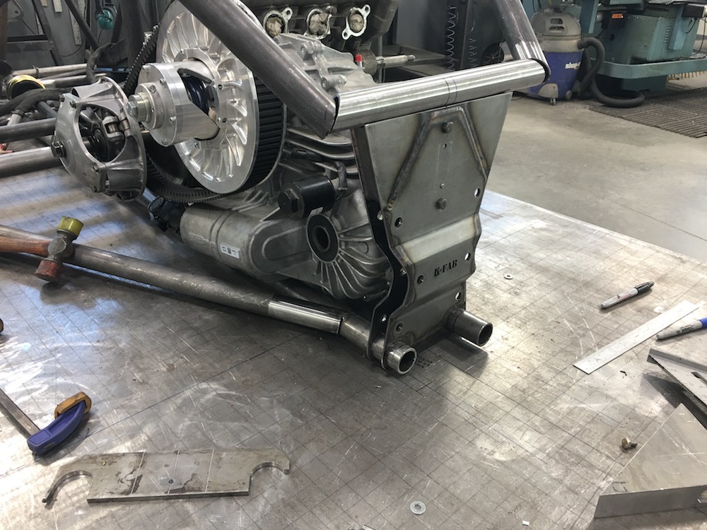
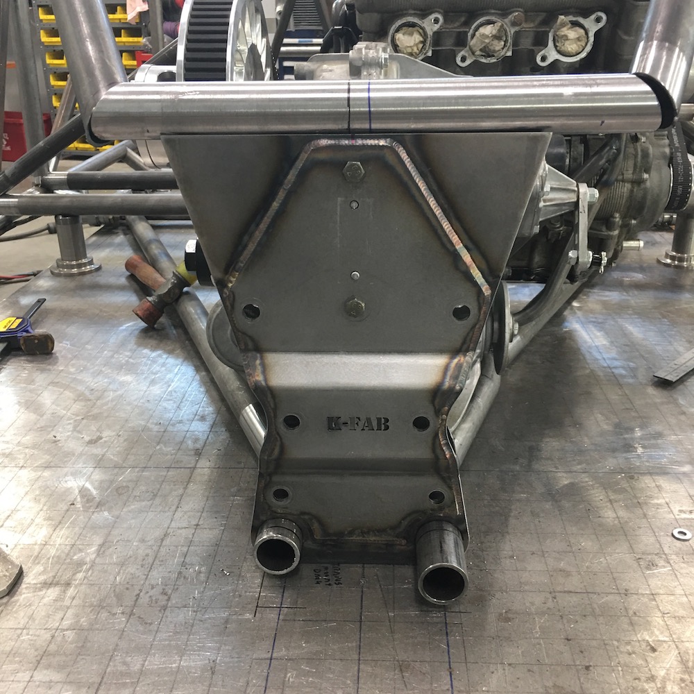
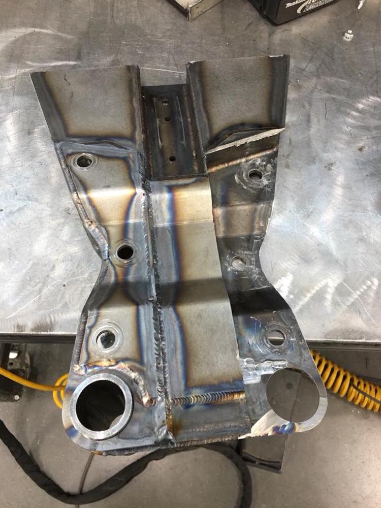
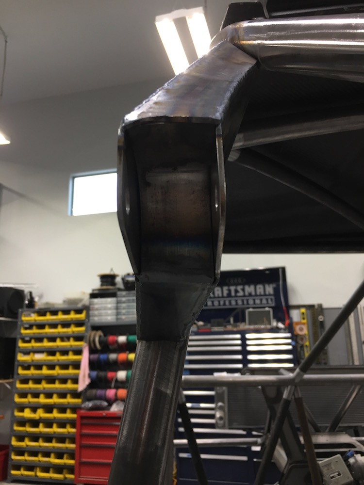
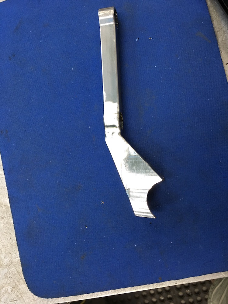
Rear bulkhead porn. Damn this turned out nice!
Three days of shop time are at my disposal starting now.
More to come - billet 7075 transverse will get started on later today or tomorrow.
Had a great conversation with Benihana - I'll be getting axles fairly soon, a grill and he's making some killer headlight and tail light pieces. I'm excited about this.
Waiting on my steering column stuff and windshield wiper mechanics to show up. I found a complete Lexus turn signal and wiper control assembly on Fleabay that I think I'll be able to adapt quite well and the wiper mechanics are out of a Chevy Cruise - I'm hoping (assuming) that GM wiper arms are all pretty much the same tapered mounting pin setup so I'll be able to source an appropriate arm for the wipers.
Just making sure things fit like they're still supposed to. So far, so good.
Had to throw the door on for full effect.
Ever see those cut away drawings? I have one in real life.
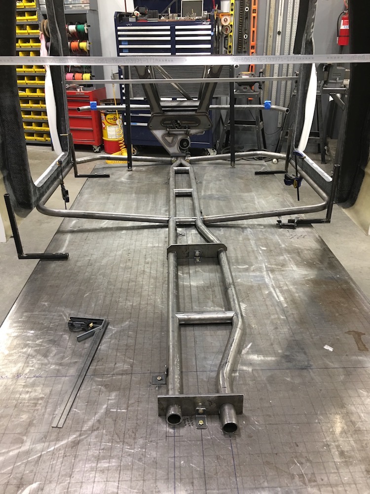
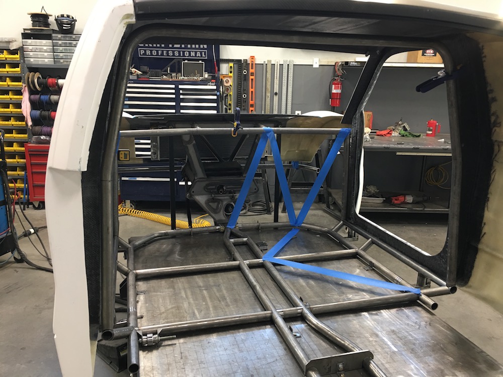
Cleaned up the down bars, got the rear cage bracing all tacked together.
Putting the bed side in place gives me an idea on how to do the back section of the chassis - all 1"x.065. It's not holding anything other than fiberglass, some panels and a spare tire.

Got a lot of room to get creative with for that.
I still need to tie the top and bottom bars together but I have to put shocks in place first. I know they're nowhere close but I need to see it first.
The bolt in the square tube, behind the cage, just up above/in front of the bed corner is the upper shock mount - it's actually about .5" inside the back of the cage. Gonna be interesting...
More tomorrow - got all day to work on it. Woo hoo!
Feb 10, 2018
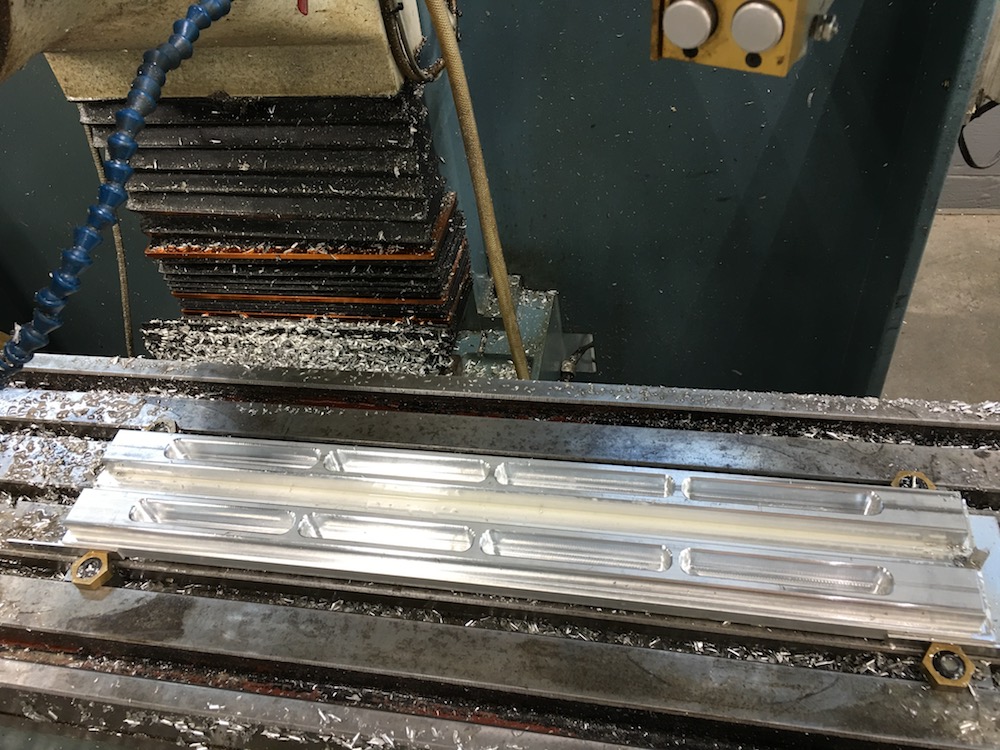
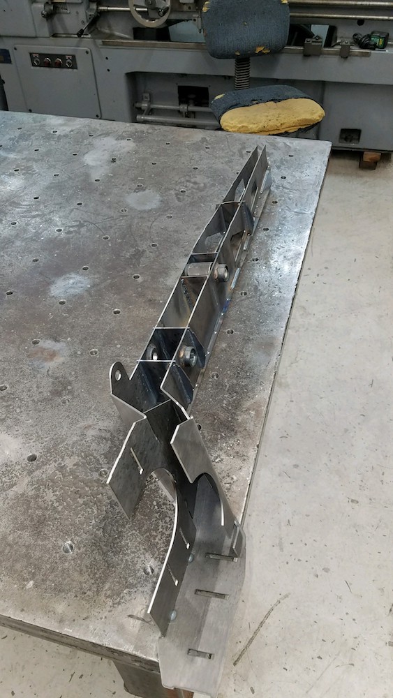
Lower transverse links are in process:
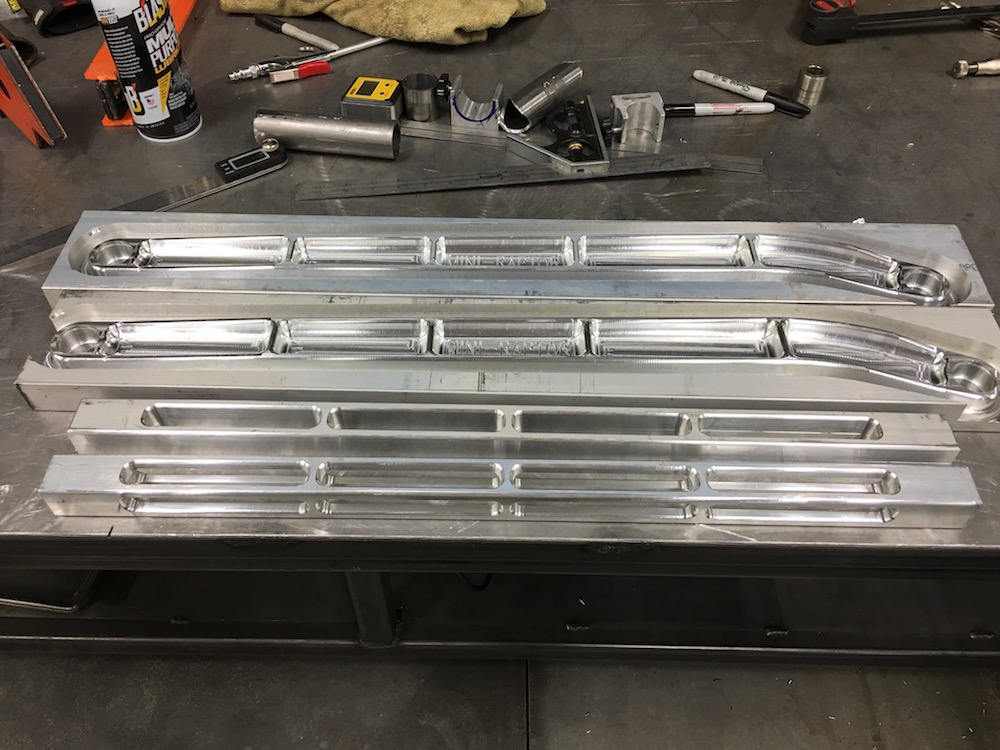
Rear Lower Links half way done:
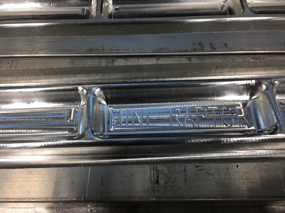
Gotta have the logo in them!
Rear transverse toe control links (a.k.a. rear tie rods):
Today's work. The tie rods will get tapered ends where the heims go in. Gotta make a jig so I can chuck them up in the lathe.
1 square inch of material, should be good enough. 7075's pretty tough and it's just a tie rod:
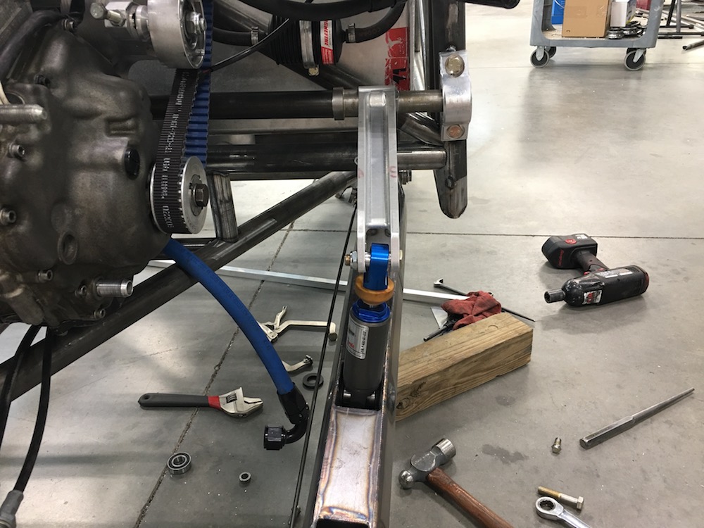
Feb 11, 2018
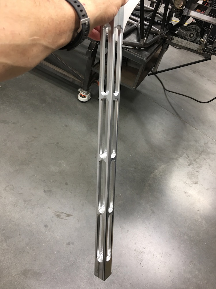
Rear links are almost done.
The tie rods are finished - need to get a new 5/8 tap, the old dull one I have and the 7075 didn't get along well - lots of lube, lots of grunting but good results.

The upper arms still need to have the heim end done - hopefully tomorrow. Still trying to figure out what I'm going to do to them. Probably a tapered cut of some sort down to a 1" square end. Then it's more drilling and tapping. I might give them the same treatment that the tie rods got and just do a taper cut in the lathe.
The ends of the links taper to fit into the bulkhead. I might have to clearance them a tad more - will see in a bit, as one of the trailing arms is on it's way here - hopefully arrives tomorrow or Tuesday.
Starting to look like something here:
Lower arms to be finished next and the rear suspension parts will be finished. Woo hoo!
Does anyone know if you can anodize 7075? I'm under the assumption that you can't but I've seen some links online that are supposed to be 7075 and anodized.
I plan on getting all the billet stuff tumbled and anodized before the whole thing gets assembles. I'm going to have a lot of little aluminum bits on the car.
Feb 14, 2018
Finished the links:

Feet just for Bullnerd.
Trailing arm arrived yesterday too:
There are a few snags. I designed the links to be used with heims. I switched to uniballs and that caused some clearance issues.
So there was some pocketing required:
There also wasn't quite enough distance between the carrier and the arm to let the carrier "steer" as the suspension cycles.
More clearance: (this was sort of expected. We drew/designed it tight.)
Got stuff put together (discovering a few more tight spots - there is a redesign of the rear bulkhead in order).

So, why isn't the shock laying over enough? Looks like the pocket isn't quite right AND the shock end is too short. Fortunately they make longer ends with clearance.
Had to put the bedside in place and see what it looked like - I'm happy!!!
Four inches from full bump:
There are a few things that need to be fixed and figured out but hey, it's custom, one off and shit like this happens. As flyer said I need to learn SolidWorks - would have saved quite a few clearance issue things.
We're going to widen the rear bulkhead a bit and that will solve 90% of the problems I'm having, along with changing the shock ends and all should be good.
More to come.
Feb 15, 2018
Here's the suspension at full bump - tire bottom 4" from bottom of the chassis:
Which puts the swing arm here in the cage:
Shock angle is just about perfect now too - the top of it is actually right where it's supposed to be. Drop the arm and, well... there's a pocket clearance issue. I'm looking at extended hour glass shaped pieces - will probably make my own that fit really close to the pocket at full droop - only cut the side that is in interference, leave the other side straight. Minimal strength loss.
Onto the frame/arm issue:
This isn't a race truck - it's a fun desert runner. So having one back wall tube not intersect at a corner isn't going to be that critical - all the driving forces and the main hoop are in the B-pillar area, the back can hang a tad for arm clearance's sake.
So here's the big issue - the links I made were supposed to use heims. Those had all the clearance needed.
Then I get stupid and decide to go with uniballs, not thinking about clearance, not thinking about rotation of the links while the suspension cycles. Heims had that covered.
I've dropped back and punted for the moment:
I've clearanced the links at the bulkhead:
Upper:
Lower:
The jamb nut was too close to the plate so that got knocked down a bit:
And the outer end of the lower link needed just a teeny tiny bit of massaging:
I still need to do a bit of sanding for a little more clearance but at least there's no tolerance fit anymore. I'm not getting witness marks when I bring the wheel up to full bump.
BUT - and this is what worries me - the droop angle from horizontal versus the bump angle is probably twice as much, which means twice as much rotation which means twice as much clearance needing to be cut.
I'm going to rotate the chassis on the table next week so I can drop the suspension out without table interference. Then I'll see just what happens when I let it drop out to full extension. If I have to remove too much material in the arms, I'll cry and then go cut new ones that have heims at least on the inner ends (damn, shit, F*&^).
There is the thought of taking the bulkhead and cutting the forward side plate, removing the two forward "wings" of the piece and spacing them out .5 to maybe even .75". Discussion of doing a new one that's wider has also happened, but I'm already at the limits of the links fore/aft. If there's a change it has to move the links forward at the bulkhead or there will be more binding.
Mar 22, 2018
Back at it.
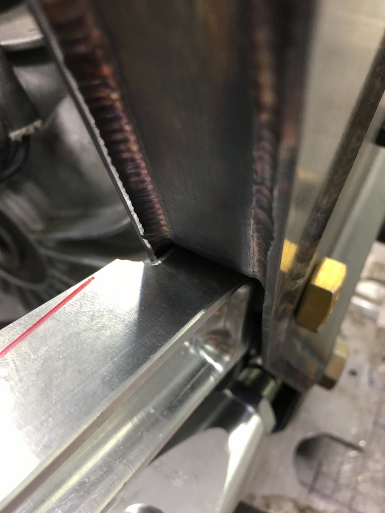
Took the back bulkhead and cut it up. Removed the front two "wings" so I could get some clearance between the plates and not have suspension components bashing into it.
Then I added some shoulders on the spacers; .125" more on the rear and .275 more on the front. Nothing hits now.
I'll make a couple of plates that will position the "wings" appropriately. I need to put a tranny drain access tube through the middle of the bulkhead too. Missed that...
I'm a tad pissed off at myself for grinding clearance into the links - at least I only did it on one side.
I'll get this bulkhead issue fixed and then it's time to rework the two main cage hoops. The miter joint at the a-pillar has to go.
Mar 28, 2018
So the "wing" mods worked out. There were some other clearance issues that I had to address and will still have to but I have progress.
Here's the spacing for the pieces I cut off being taken up with an offset plate:

I mentioned some other clearance issues (remember this thing was designed with heims in mind instead of uniballs in the ends of the links). The lower links ended up dropping down onto the ends of the lower rear main chassis tubes and wouldn't droop out much past horizontal.

Which lead to cutting notches in the tubes so the links could drop down:

FINALLY I was able to move the chassis around on the jig table and check droop. I have an honest 18" of travel right now with 4" of ground clearance at full bump. There's easily another couple of inches of droop available once I get the two pockets that the links fit into in the arm cut out a bit more. There will be some shock mods (longer lower end) and some arm mods (doesn't allow for the shock to rotate forward enough - the shock end interferes with the pocket as the arm drops out. I'm thinking that I should have about 19" of non-interference movement once everything gets machined and made to work. What a pain in the ass!!!

The upper link's outer jamb nut hits the top of the arm:

And the lower link hits the top of the pocket it fits into. A bit of mill time and around .100" of material removal from each spot will make the world good.
Once I get all this crap clearanced out and make sure everything moves like it's supposed to I'll move on to making the new main hoops of the cage. There are a couple of miter joints that have to go and I'm not happy with fitment of a couple things.
I need to get some seat time with Bend-Tech and figure out how to do the main upper hoop(s). Ah the joys of learning new software (like I should have done with SolidWorks from the beginning...)
Apr 9, 2018
I'm back - guests are gone and I get to play in the shop again. Woo hoo!
Got the cage redone - no more mitre joints but there are some sleeved spots... I SUCK at bending.

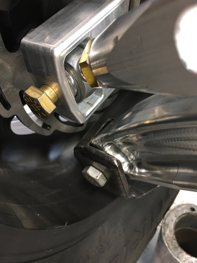
Presently working on shock ends so they clear the pockets on the trailing arms.
Apr 30, 2018
Guess it's been a bit since I've 1) done much on the Mini-Raptor and B) posted.
Butt plugs finished and ready to hold the shock in place correctly:

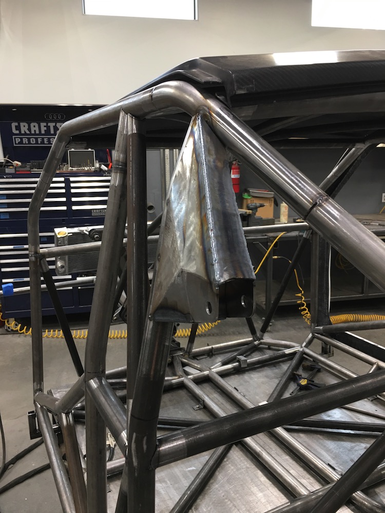
Redid the back of the cage and got it all nice and tidy. Some of the best fitment thus far too.
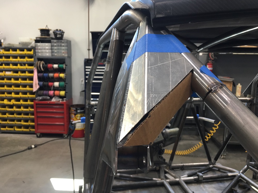
Presently working on getting the upper shock mounts done. As The Wizard put it, CAD (Cardboard Aided Design) Metal Origami. I'm really pleased that this all went down with NO tossed pieces! WOO HOO! (for once... shit...)
Outer plate:
And the inner plate in place now too:
Hope to get more done tomorrow.
May 2, 2018
Spent a couple of hours massaging the inner plate's fitment and then making the three pieces that fit between the two plates.
Still have a little detail work on this part and then I'll start into the tie in that goes to the down bar on the right.
vThen I get to do it all again in a mirror image. Oh the joy! - was smart and have already cut the two main plates out and marked them so copying won't be bad. I'll do the same with the two tie in plates too.May 7, 2018
Upgraded the CAD system to ACAD (Aluminum Cardboard Aided Design)
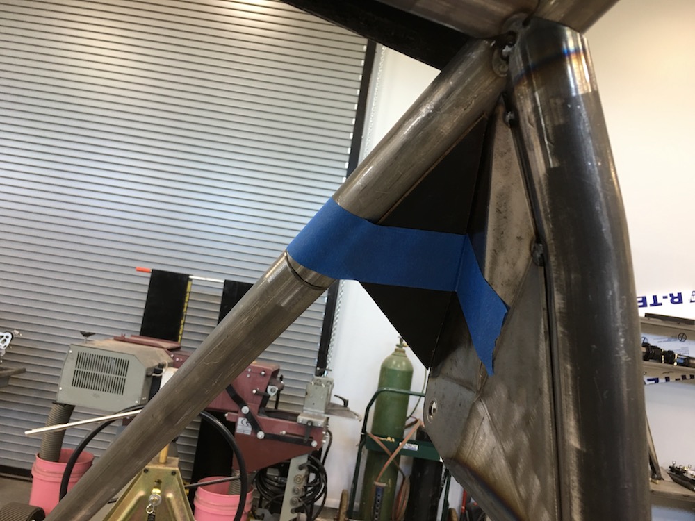
Once I got all the aluminum and cardboard mock ups figured out I transferred it over to steel and stuck stuff together while still on the chassis.
After it got tacked, it was full weld time.
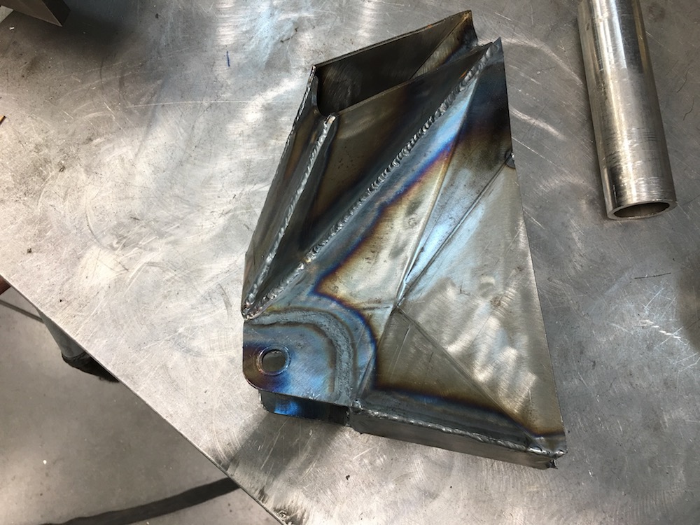


It darned near clips back in place. Too bad my welding looks like shit! (I'll get an inch or two of really nice beads then, meh. Crap)
I have some welding to do around that corner of the cage then I'll stick it back onto the chassis and start on the other side. Had planned on doing this over the past couple of days but ended up being busy with other stuff.
Hopefully today I get to go down to the shop and play a bit.
May 30, 2018
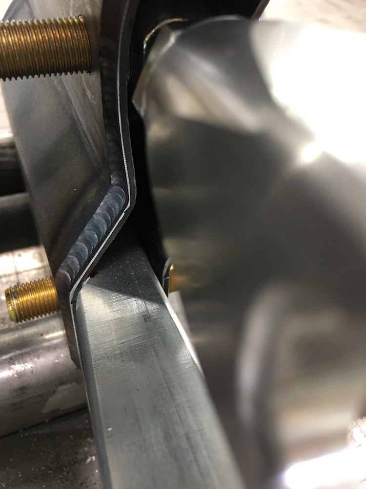
More redone stuff, straightened stuff, bars, fab, blah, blah... I'm getting really good at redoing this thing. I have to laugh at my buddy Jay (guy who built the Coyote) - I was bitching about how redoing parts of the cage again and again was getting old and he just smiled and said "Yeah, welcome to the fabrication world." He redid the first Coyote's roof line three times to get it right.Got the rear shock mounts done, minus the doubling plates. I'll freely admit that I ground off the shit welds, made everything nice and pretty and then I'll get the doubling plates cut - they're gonna cover up the areas I ground down anyhow so it needed to be smooth (that's my story and I'm sticking with it):
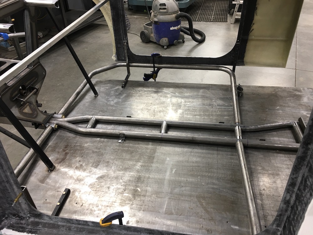
Also got the rear of the cage tied into the bottom of the chassis:

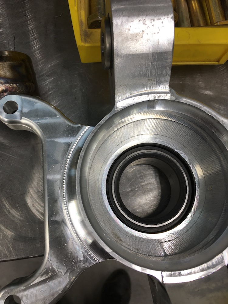
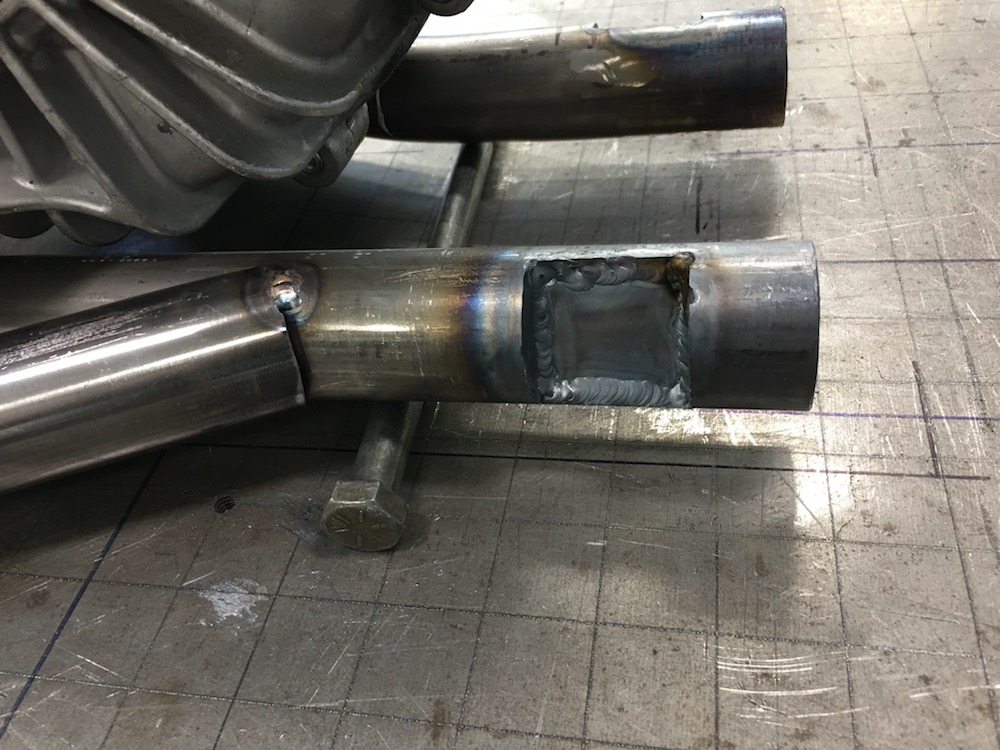
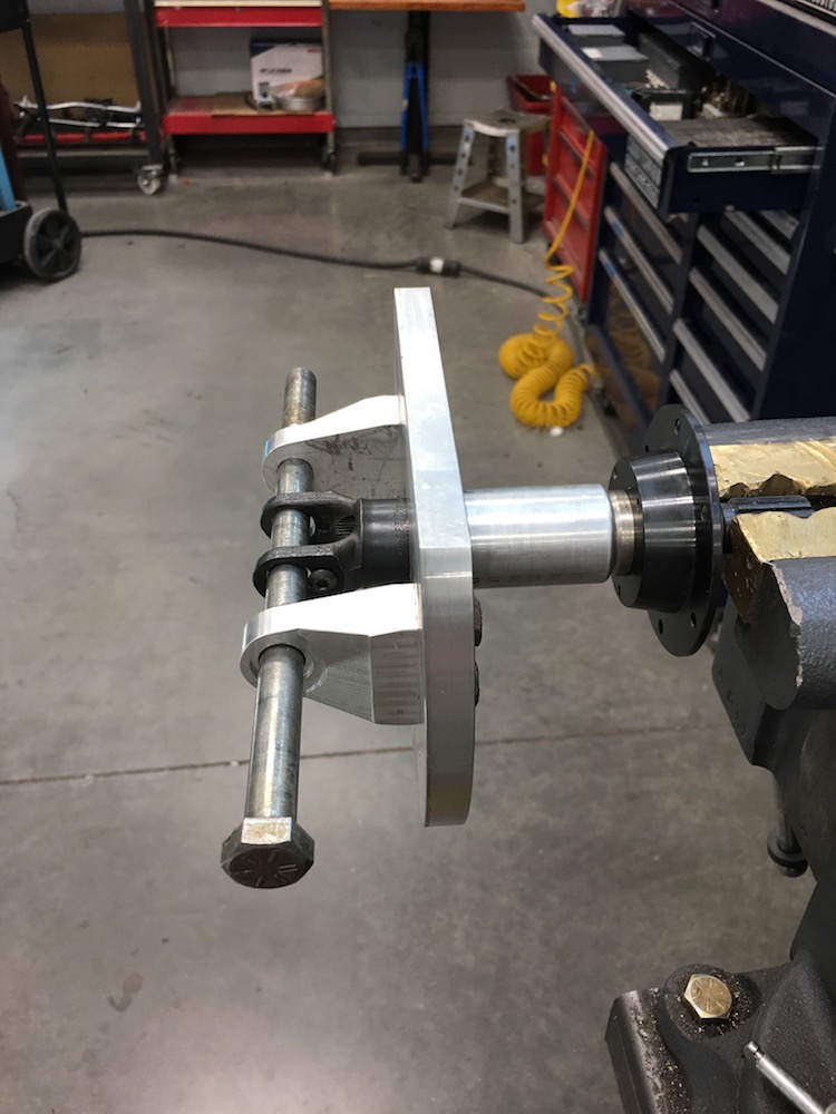
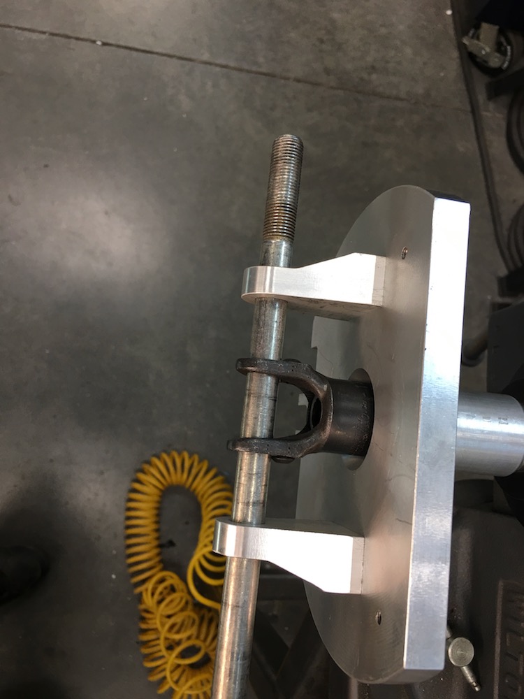
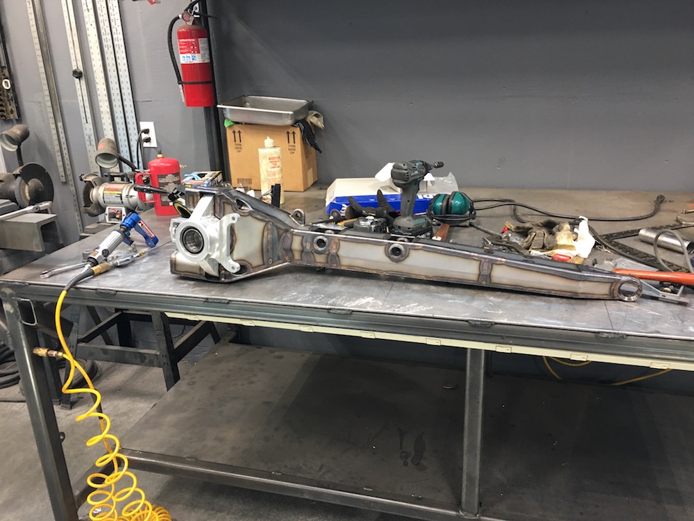
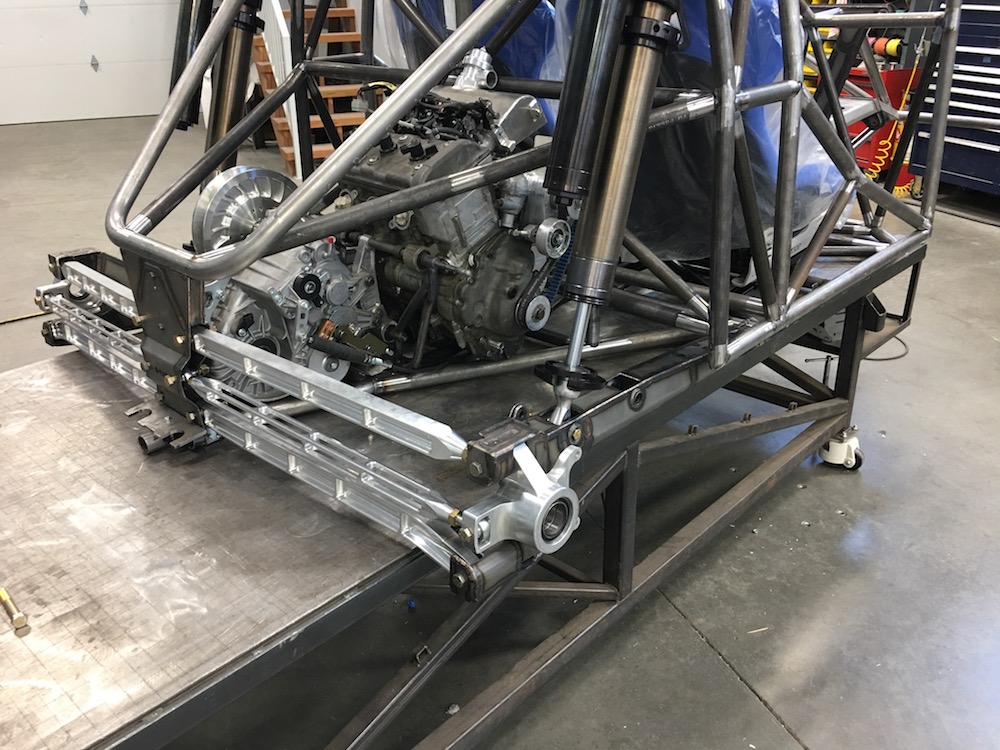
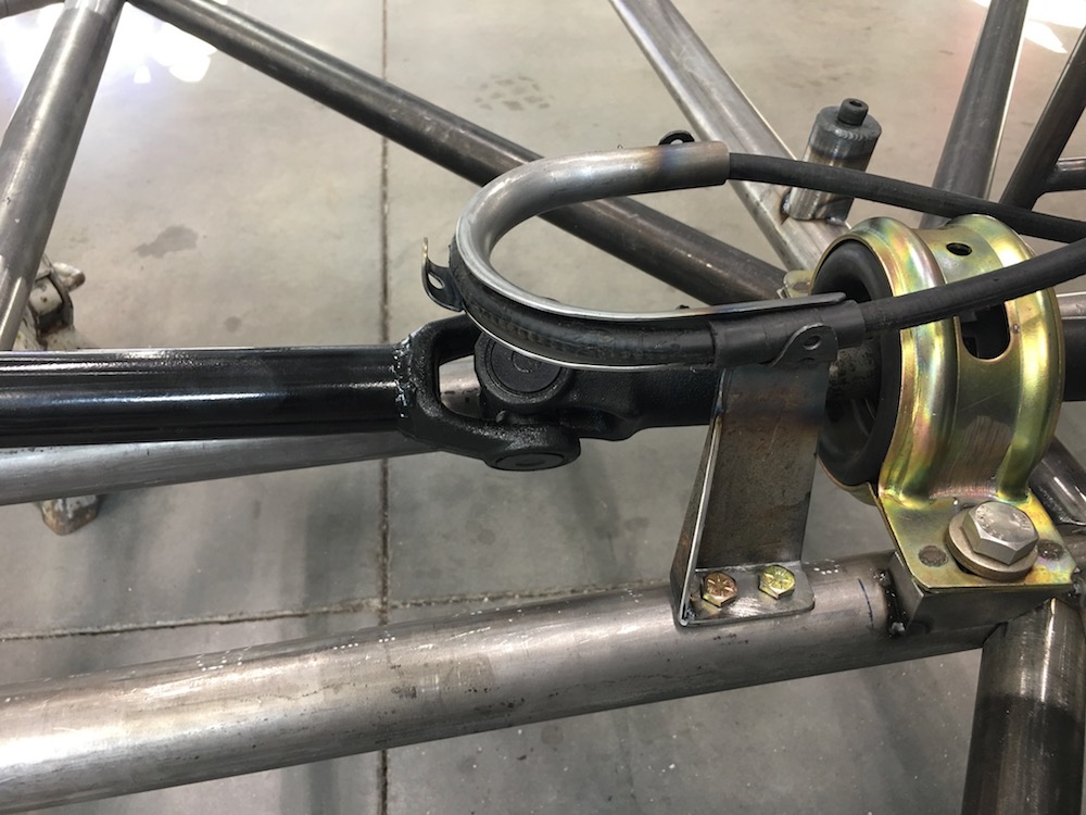
Tended to the drive train - made mounts for the center bearing carrier:

The front shaft ended up being 3" short so I had to modify it. I took the daaboots route and made my own using the OEM u-joints.
I was kinda (un)surprised at the good ol' "Made in America" quality of Polaris. They may make a decent machine (we love our XP) but their quality is something to be not overly impressed with. The clocking of the u-joints was off by about 5 degrees. And people wonder why the drive shaft on the XP likes to vibrate itself to death?
First step was to cut the ends off - machined them from the ends of the tubing. Turns out the tubing is 1.25x.065 - and I have a bunch of it in chromoly.
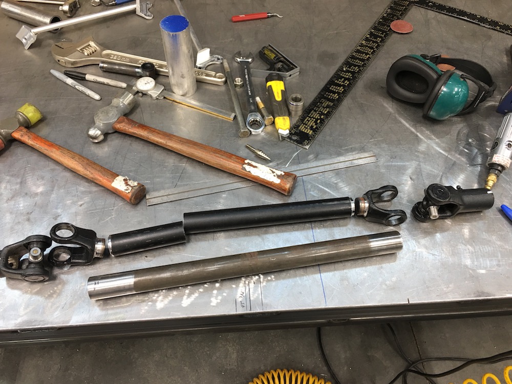
It turned out really well:
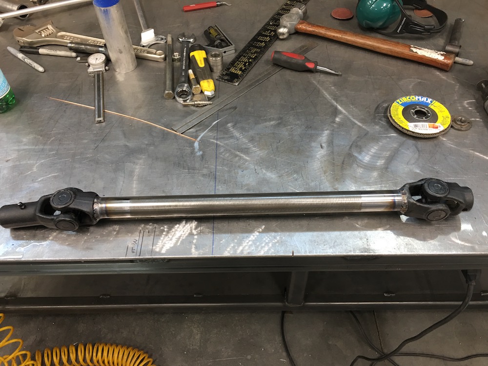
Test fit - works perfectly:

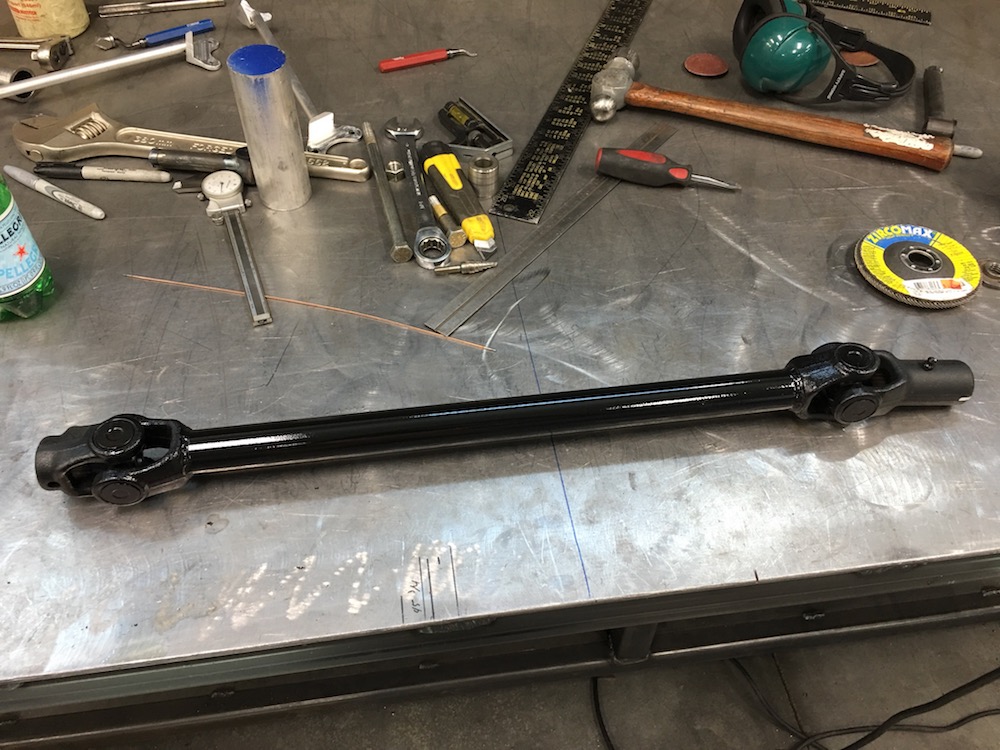
A little rattle can work and it looks like OEM (with the u-joints clocked perfectly, ahem, Polaris):
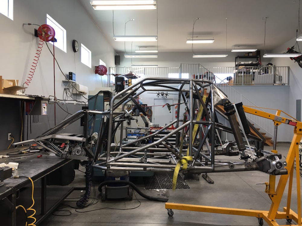
As I've built this thing the cage has kicked my ass. Trying to make a bunch of toooobing fit inside a flexy shell's proven to be a bitch. I have a bunch of used tubing sitting in the trash bin presently.
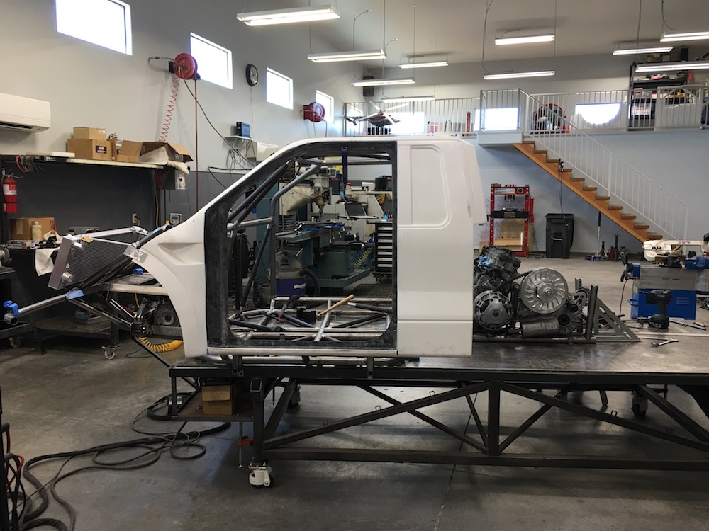
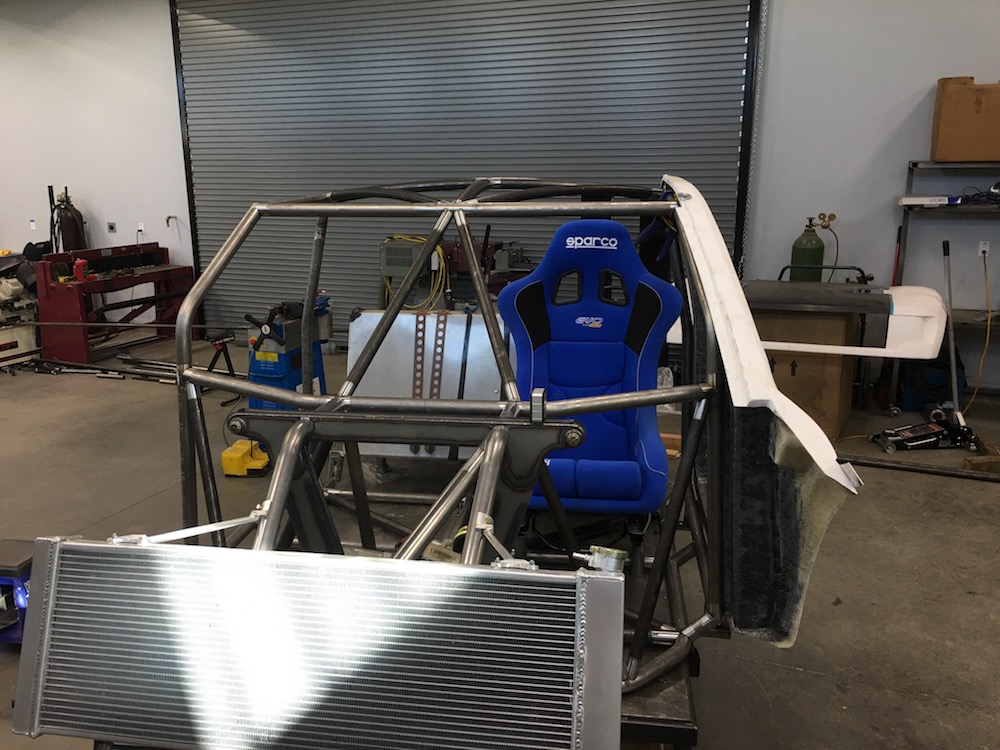
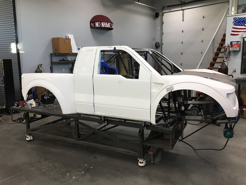
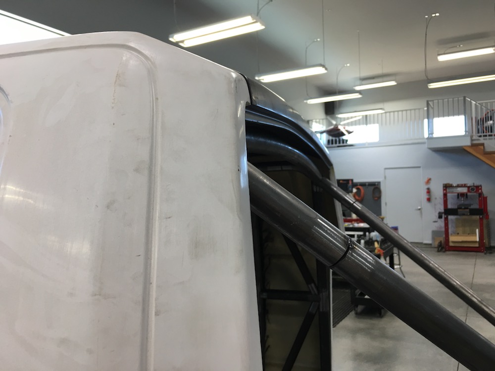
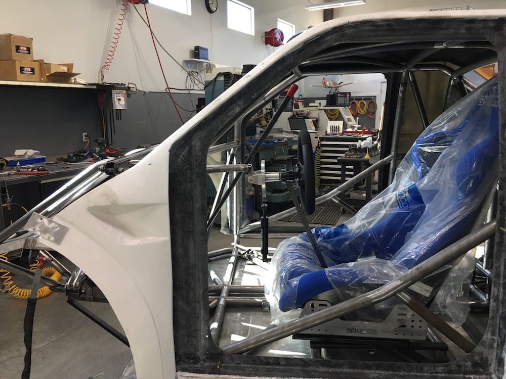
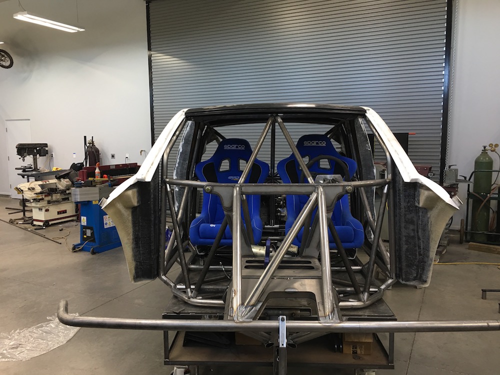
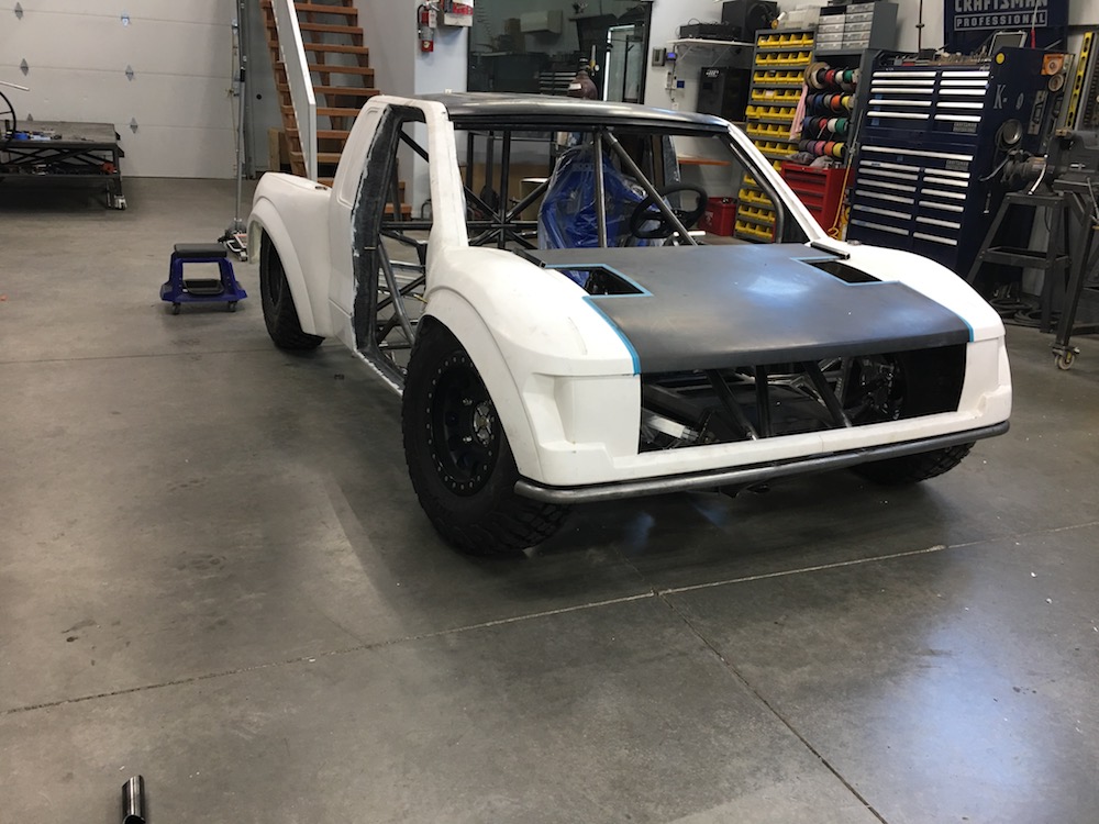
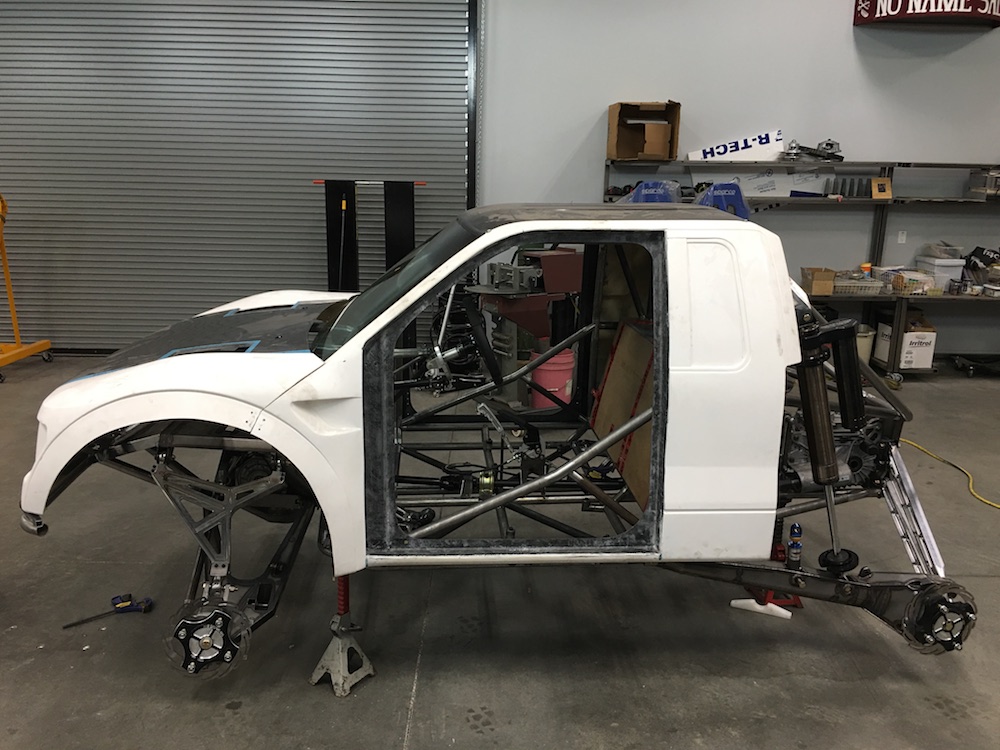
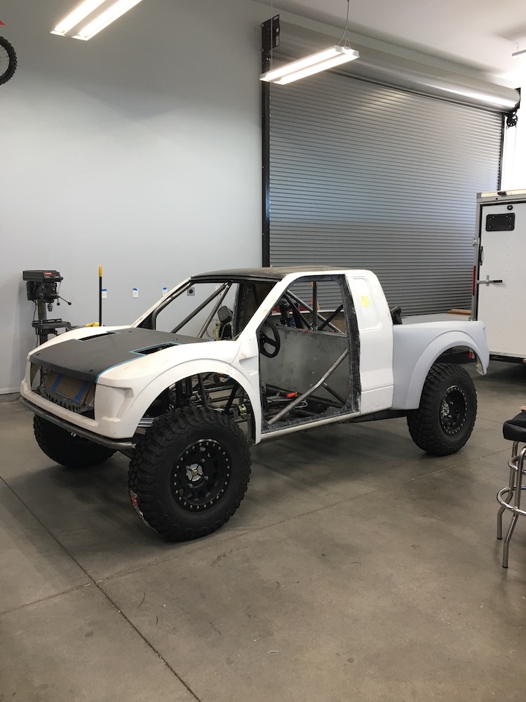
I put the body on again and started looking at placement of things inside, like the seat, steering wheel and pedals. I've had the body set up so that it sat on a some locating posts. It was time to go ahead and get it mounted (temporarily) to the chassis in the correct, permanent place. I made sure everything was level and straight in relation to the bottom of the chassis (I know it's flat/straight/right)
There were a couple of things that didn't look right; there was a big gap above the right rear shock mount and none on the left (sorry, no pics) and the front upper windshield cross bar was too low - you can see it here (older pic). You can see light between the bar and the lower lip of the roof line - from a front view this was about an inch+ of light.
From the front view (thought I had one) it sat about 1.5" low into the windshield opening. Not good, not pretty, no bueno. It also lowered the roof bars a bit more than I liked - too close to my noggin.
Off with all the bodywork again, out with the cut off wheel and out go the front upper bars and braces. Fortunately (for once...) I was able to salvage the bar and mod it to fit like it should have in the first place and mod the roof bars (shorten). Unfortunately I don't have a tube stretcher so I had to redo the front down bars. I ended up with more brain container (mine's about half empty anymore) clearance, better vision and a more aesthetically pleasing look:
Back on with the bodywork and then it was time to tend to the rear cross bar. Turns out it was off by about 1/4" on each side between the shock mounts, which made it low on one side pretty badly. More cut off wheel work, more grinding (saved this tube too!) and then back in place nice and level. Not sure how I screwed this pooch as badly as I did but it's all good now.
The last main chassis thing I needed to do was the mid bars from the top of the rear bulkhead to the mid line of the chassis. A quick sighting looked like I was going to have shock clearance issues on the left side and shock and engine clearance issues on the right side. I was also worried that the clutch on the trans may be interfered with on the left side.
Turns out my worries weren't legit other than it being a bit close for my liking to the shocks. A quick 5 degree bend and tada! Clearance!

They fit in place like they were meant to be there! (guess they are, eh?)

Right trailing arm is finally underway too - Mr. Space-X said he hopes to get it done in the next week or so. I get that and I'll have a rolling chassis.
Time to start working on the cabin layout.
May 31, 2018
Chassis - main stuff done.
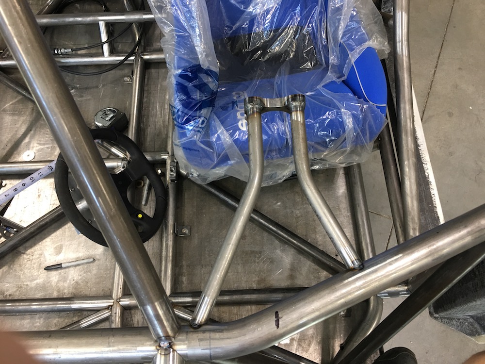
Time to head inward. Put the seat in, hold a steering wheel out in front of me and make vroom, vroom noises.
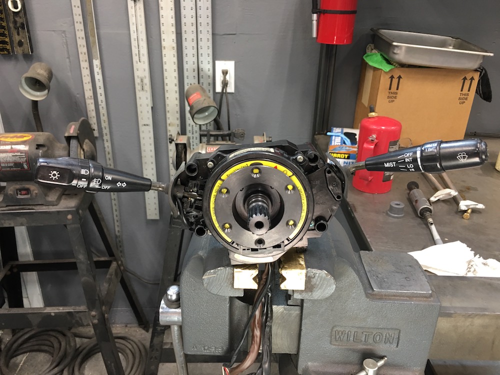
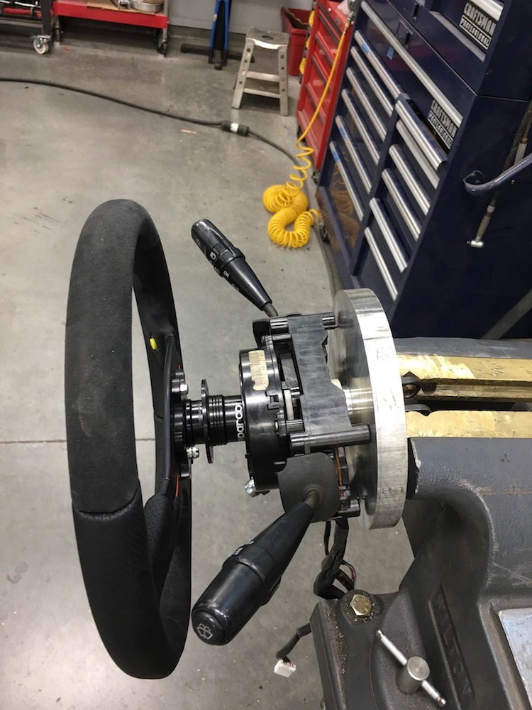
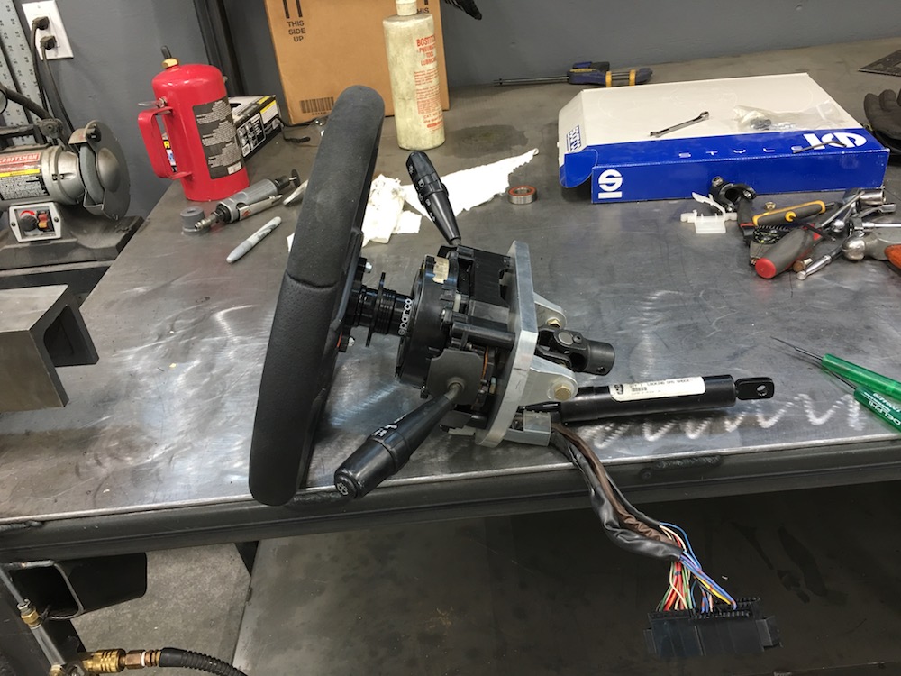
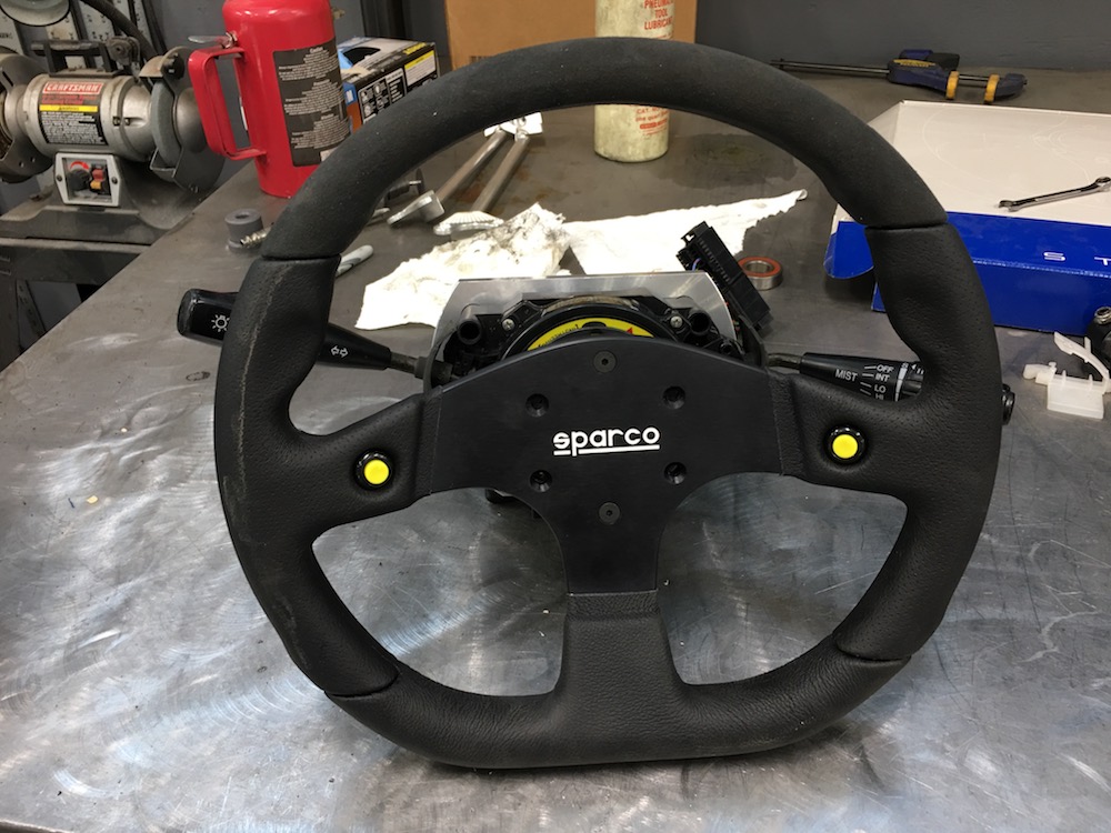
I couple months ago I got on Fleabay and purchased the steering wheel controls (wiper, lights, blinkers) from a Toyota - the Mini-Raptor's gonna be street legal so why not make the steering column as "normal" as possible? It drives me nuts that the RZR's turn signal is a pain to use - bad location, no self cancel. I got one that has a fog light switch so I can operate my light bar from my steering column. One less switch on the dash, or room for one more feature depending on which way you want to look at it.
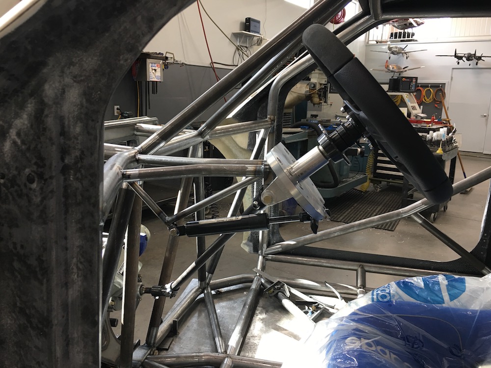
Anyhow, I've started the steering column. It'll have tilt and is a quick release. I'm using the tilt setup off an XP - it's simple and effective.
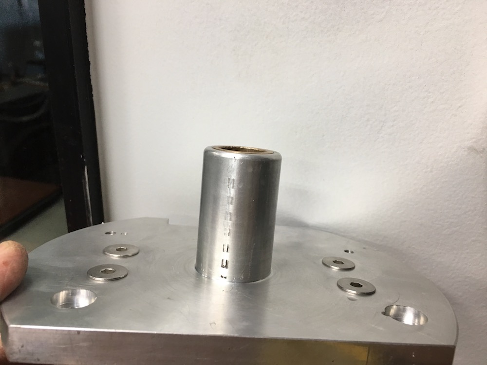
The shaft is a short, stubby thing - the pivot for the column has to be in the middle of the u-joint. I have a fairly steep angle down to the steering box too, so shorter is better at the moment.
When I ordered the Sparco wheel I ordered their quick release setup too, thinking I'd be getting a shaft and a quick release hub. Nope, it's weird - the shaft isn't a shaft, it's a plate. So I counterbored the back side and welded in my shaft.
I needed a way to drive the signal canceling "barrel" thingy (I don't know what it's called...) and the flange ended up being perfect - almost like it was made for this. I had to machine the plate that's behind it (locates the barrel thingy) so the flange would fit flush - that's it. Offsets were right, depths good. I like it when things like this happen.
There are three holes (you can see the top two in the bore of the flange) that the barrel thingy pins into - that's what drives the self cancel.
Side shot with the u-joint in place.
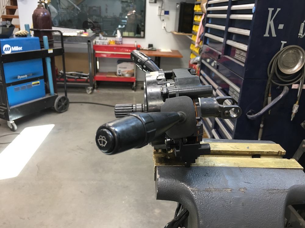

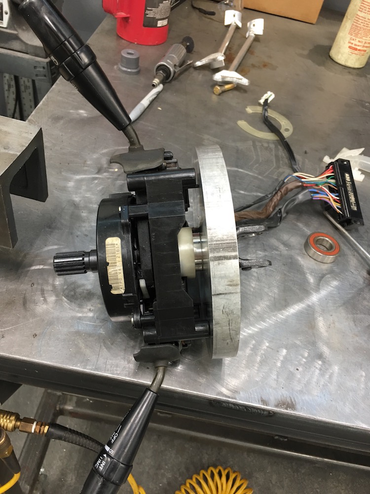
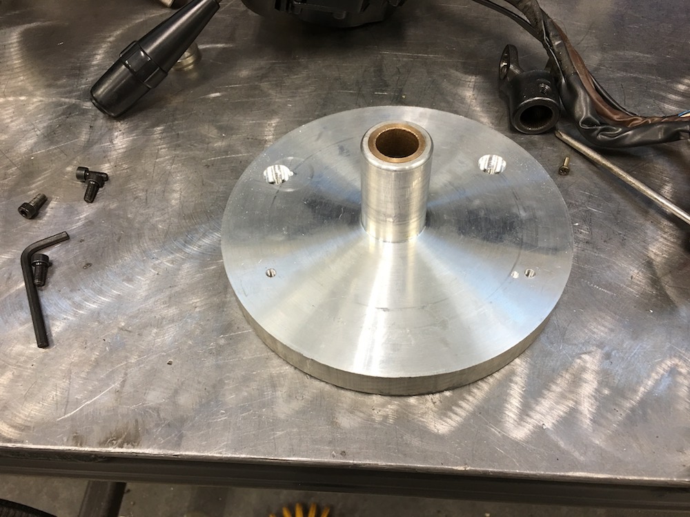
I machined a snouted plate that has self lubing bronze bushings that will be the steering column and tilt plate.
I still need to machine pockets for the four tabs that hold the column controls - the white sleeve will sit flush against the plate when I'm done.
I'll also make a pair of pivot ears that will mount to the back side of the plate. I'll leave the area between the ears and the center fairly thick and thin out the rest of it - pocket it out. I want the edge to be fairly wide so I'll have something to mount the cover I'll make for it to.

Jun 2, 2018
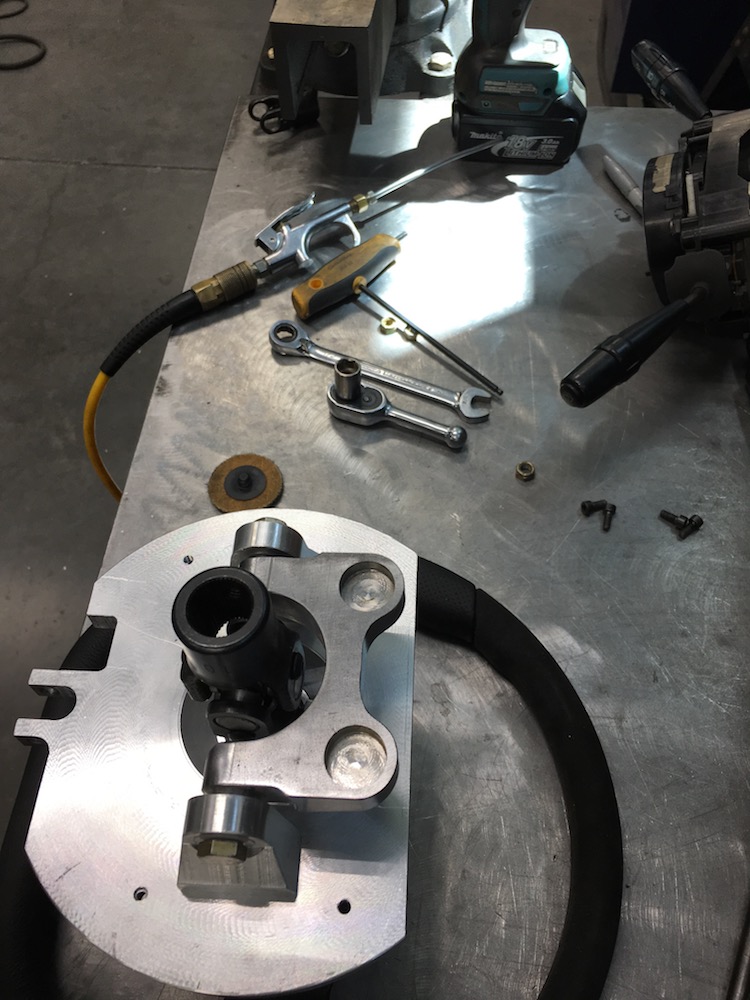
Here's the snout side of the plate. Oil impregnated bushings installed. There's a plastic piece the back of the control unit that slips down over the snout with a slight interference fit - should help keep the dirt out of the system. 2.3" of support on the steering shaft.
Here's where the snout ends up in the system once the control unit's put in place:v
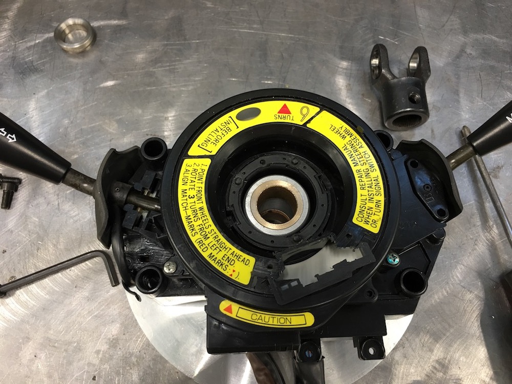
Steering shaft in place in the main plate:
Circlip keeps it all from falling apart - and the u-joint will too. It fits right up against the clip:
Pivot ears in place. Pivot point is right through the middle of the u-joint so there won't be any binding. I bolted the ears in place but I think I'm going to go ahead and just weld them on. There's a slight clearance issue with one bolt head and the back side of the control. If I weld, that's two less things to worry about coming loose too.
Side view of the steering column:
Front/Top view. I was able to use the OEM Toyota wire harness holder so the wires run just like they do in the vehicle. Keeps things nice and tidy:
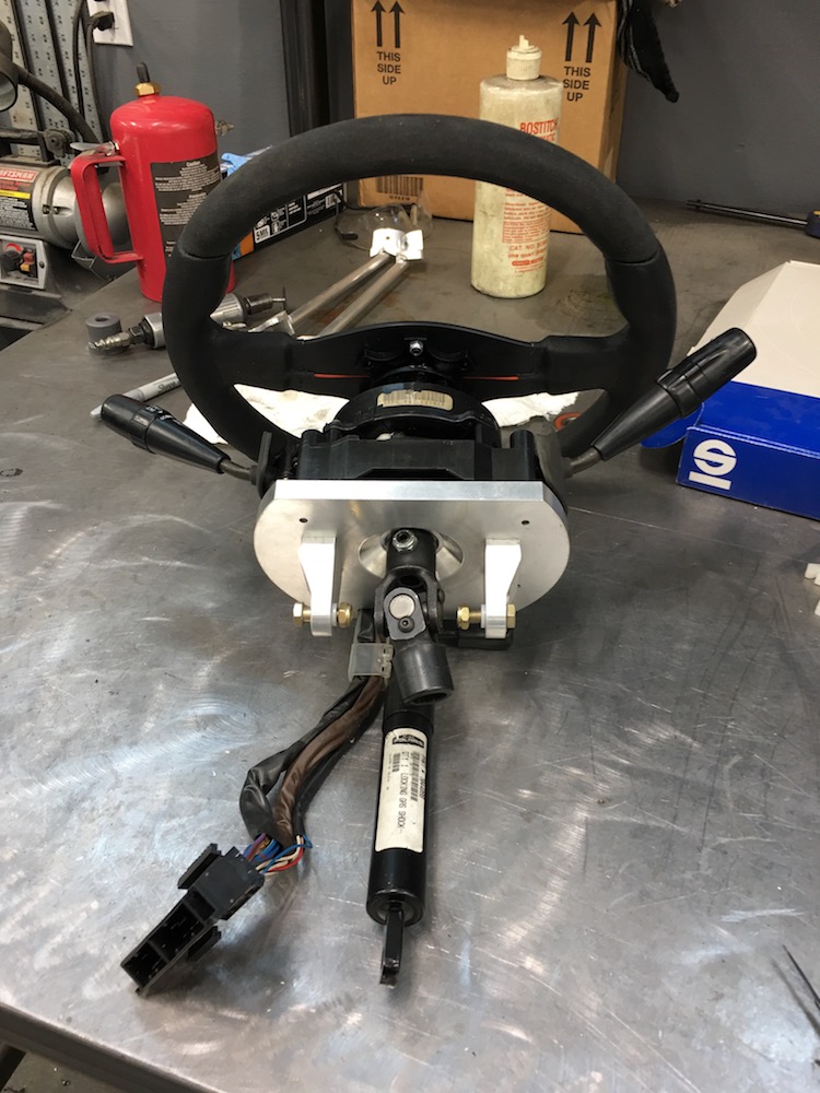
Bottom view. The lockable gas strut is for tilt. Polaris has this down and it works well. Notice the wire harness routing thingy. I did screw up and put the bolt in from the wrong side. Did the bolt before I realized that the wires come out of that side - on the bench they were laying on the other side of the two ears that the strut attaches too but once I put the wire harness routing thingy on the control box I realized the bolt should have gone in from the other side. Oh well - it all fits anyhow.

Side view of the column:
Once I start playing with composites (fiberglass and carbon fiber) I'll make a cover for the controls that will bolt onto the aluminum plate. All that stuff will be nicely hidden.
Today I'll get the seat put in it's place in space (not necessarily mounted yet), hold the column out in front of me, make vroom, vroom noises and start figuring out where the column sits in space. I'll do a temp mount of some sort to hold the column where it's supposed to go and then start working on the dash board area's support bars and such. Pedals will also be part of this process, which like the column, need to be made. I have an OEM Polaris XP master cylinder that I'm going to use (why not - it works and I'm using XP calipers) so I'll have to make my own pedal setup.
As mentioned by the Wizard - counter sunk the bolts and all is good.
Not bad for just pulling this out of the air as far as a design goes. Steering shaft had to go through something that was going to hold the column that was going to be mounted to tubing to the frame. I just winged it on the mill and ended up with a pretty cool part.
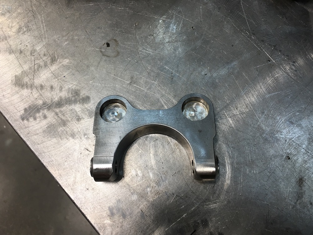
Pivot bulkhead in place on the column:
I swear it was watching me...
Test fit for height:
Top view of the mount:
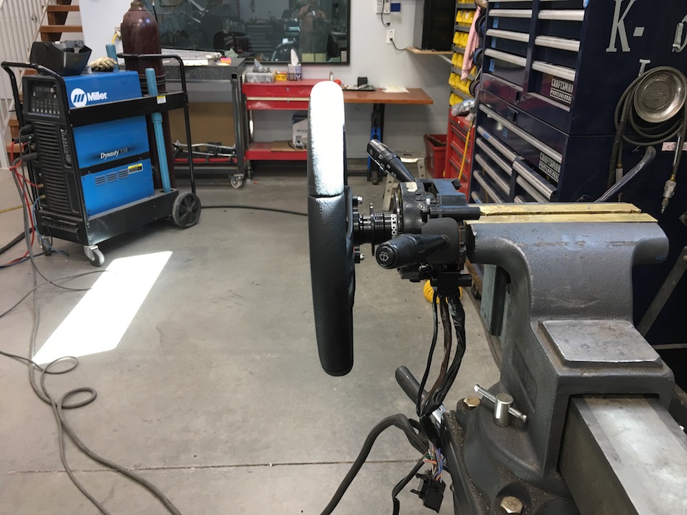
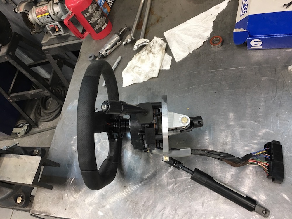
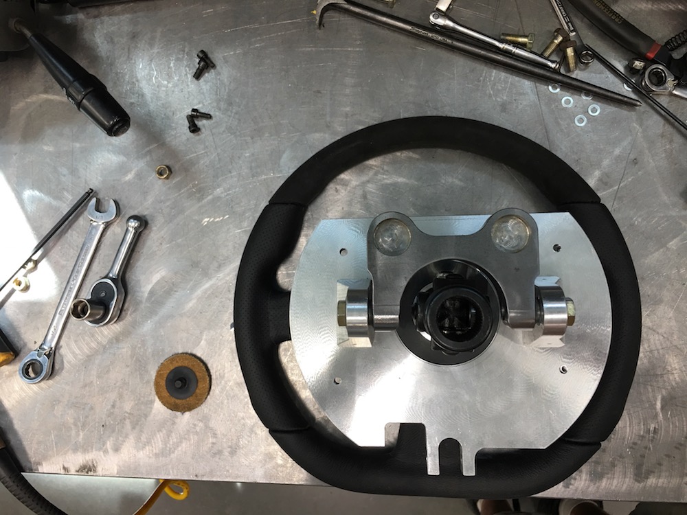
I have a tilting steering column!
The u-joints are going to be at their max deflection - I had to go and do a little clearance massaging on the bottom one to get things to line up. I'll get the top one done next and then cut the steering shaft down to the correct length.
I also need to bore the spline that gets welded onto the input shaft of the power steering unit so I can slide it farther up on the shaft to lessen the steering shaft angle a tad.

Things are moving along well. No throwing anything away today!
Jun 7, 2018
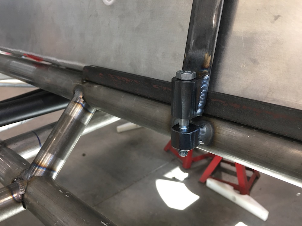
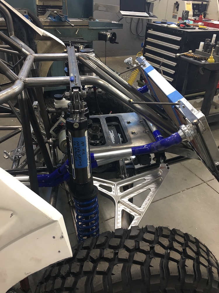
Mount for the adjustable gas strut that actuates the tilt steering - had fun making this little clevis:

Everything installed and functioning. The triangulation bar that comes from the pivot bulkhead down to just above the clevis was needed. The gas strut has a lot of force behind it and I didn't like the amount of flex I saw when tilting the wheel.
Steering wheel in the up position:
Steering in the down position:

Front/Top view of the setup. I'm pretty pleased overall with how well this came out.
I still have to weld the two u-joints that are down between the power steering unit and the rack together - will spend a bit of time making sure everything is clocked accordingly. Not sure if that'll get done today or not - need to get a couple pieces of hardware installed before I do.
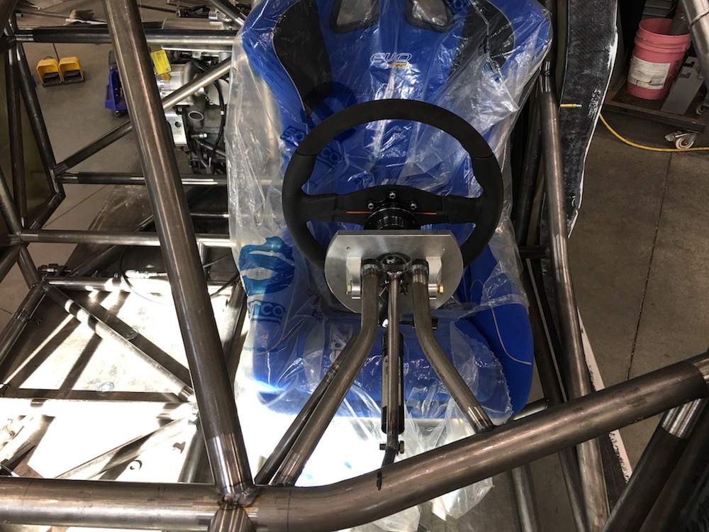
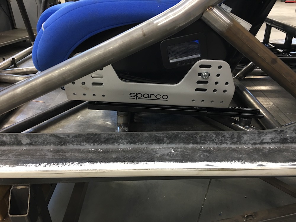
Seat mounts are today's project. I've already started them but there's still machining to be done.
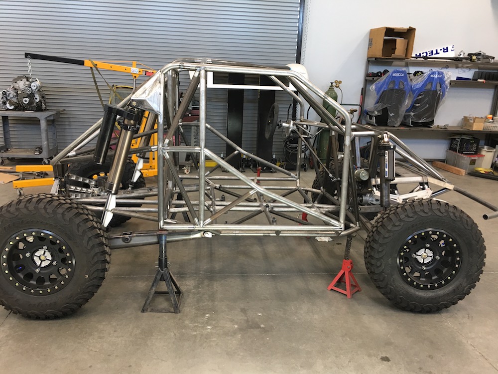
The setup axles went to Knine Racing on Tuesday so hopefully I'll have a functional set in the next few weeks. I get my other trailing arm and I'll have a roller!
Gotta start looking at how I'm going to install the sway bar once I get the arm and the Mini-Raptor sitting on it's own and off the table.
Seat mounts are almost done. Pic doesn't show the passenger's mounts and there's only three of them so far. The elbow that goes to the cross bar is a little time intensive.
My welding is getting better - at least when I can reach and not hang over things and try to push the pedal with my knee and ....
Jun 8, 2018
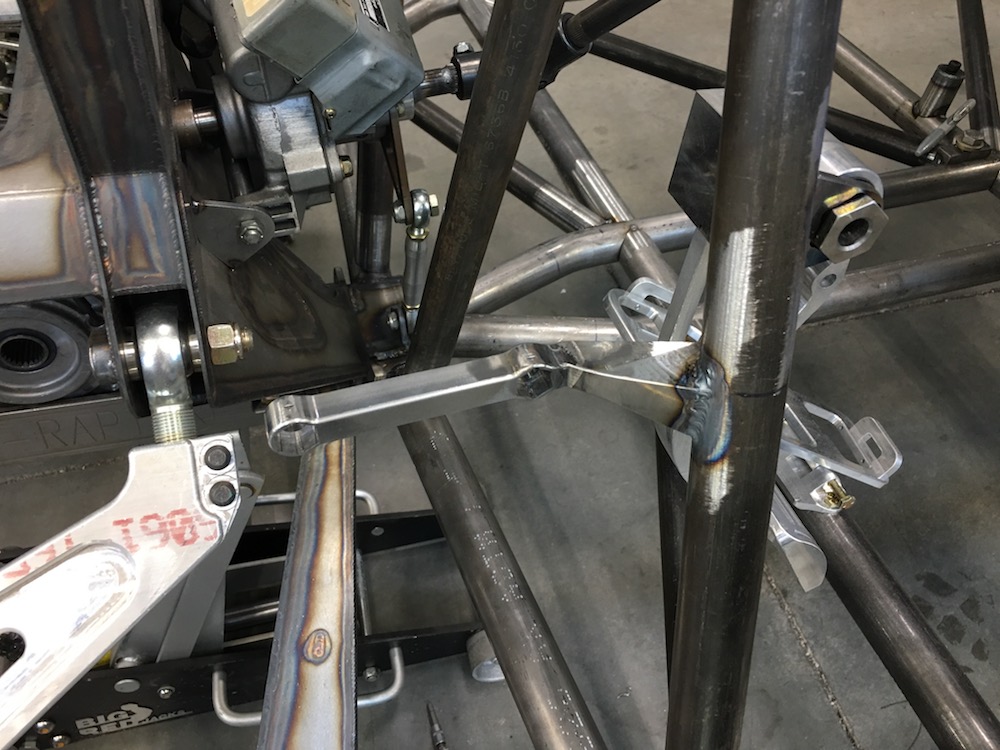
Stood back and looked at the project today and for the first time I can actually start seeing the light at the end of the tunnel. Feels kind good. Axles are on order (4-6 weeks), fuel tank is being done - Talon & Smitty are at the Finke Desert Race presently (Smitty got to ride a KTM back down the road that follows the track today - I'm envious) - but it'll show up soon enough.
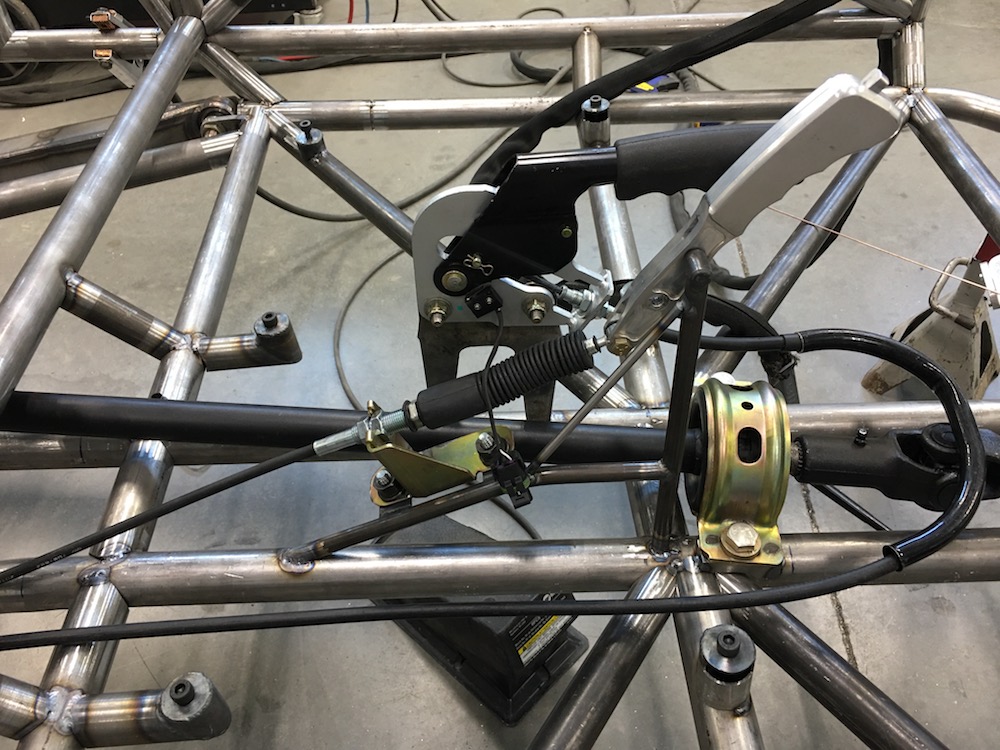
Got the seats in and did the final steering work - welded the u-joints between the power steering box and the rack together, made a stay for the power steering unit, started figuring out control arrangement - I have a parking brake lever and a shifter that need to find a space somewhere above the center carrier bearing and between the seats. I see small tubing fab in my future.
Seats from the front:
Seats from the side - driver's side fully forward, passenger's fully back - I don't think it's actually going to go back quite this far before it hits the tank.
As per The Wizard's instructions (because he is The Wizard, after all) I angled the seat bases so that when the seat goes back the seat goes down and keeps a fairly constant head clearance from the roof bars. Built in no bonk, if you will.
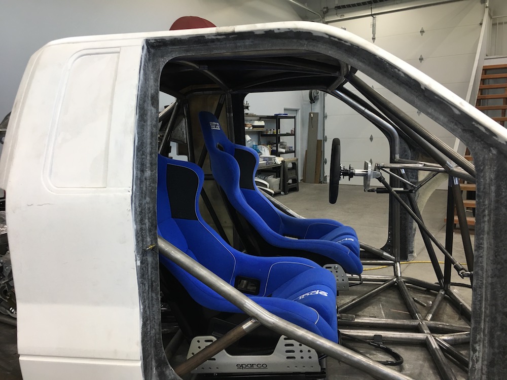
Here's a shot that shows the angle fairly well:
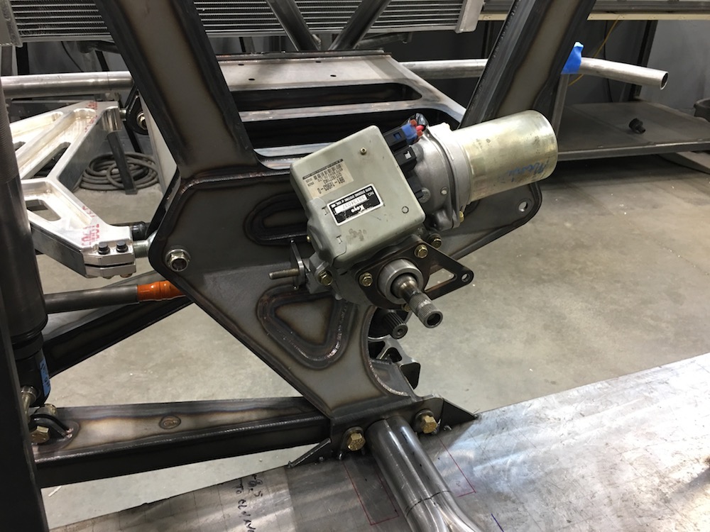
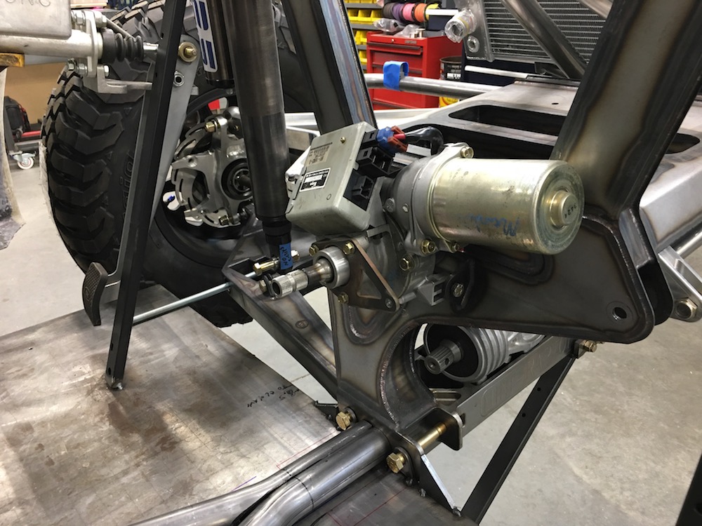
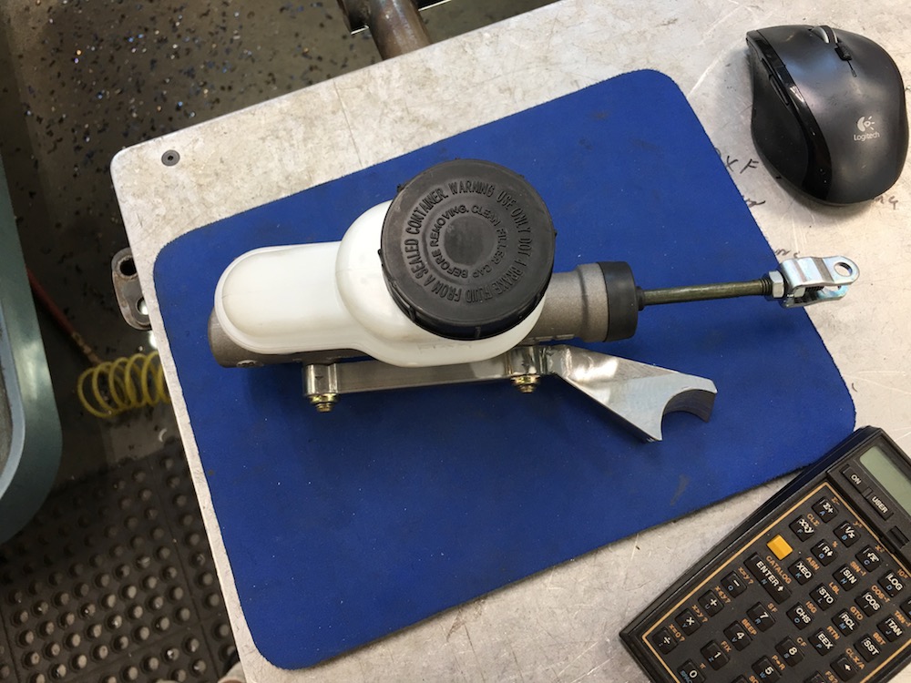
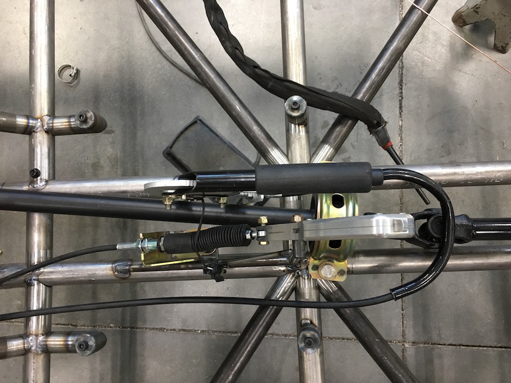
The power steering unit pivots so I had to make a stay for it:
Pedals are next; I've already sat there flexing my feet trying to figure out where they are going to sit. There's not a lot of room for the brake - I may end up modding/moving one of the bars in the chassis so it's not in the way and can be used for a mount. We shall see...
It's machine time - the pedals are going to be fun/interesting to make.
Jun 21, 2018
Been out of the shop for a week - my daughter has been in town.
My long awaited right side trailing arm is supposed to arrive TODAY!!! I'm gonna have a roller!!!Axles are on order - expect them in a few weeks.
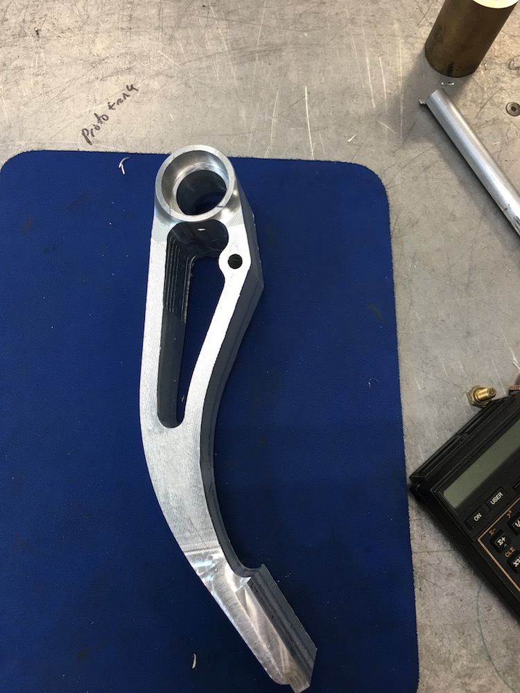
Been working on a throttle pedal. This is today's project - hopefully I'll come away with parts at the end of it.

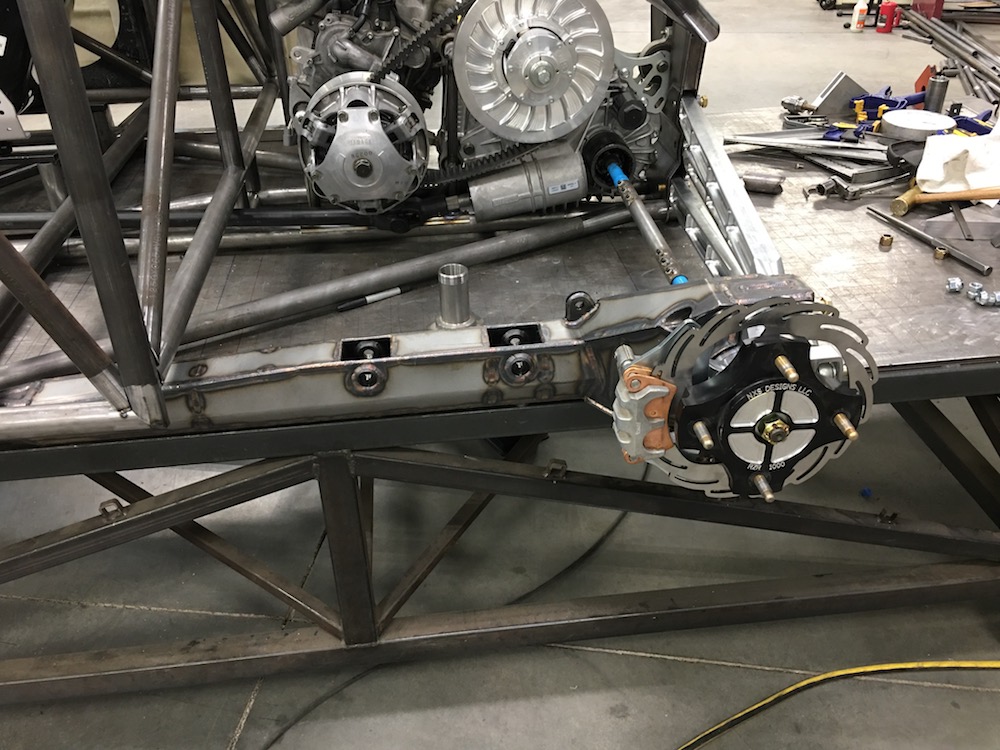
My elusive right rear arm showed up today! WOOP WOOP!!
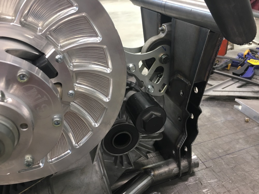
And it's now installed:
Got the pedal finished before I put the arm on.
Here's the top of it coming out:
Then it was flip it over and cut the pivot out:

Here's the bottom side:
And the top:
I'll work on the pedal base/mount tomorrow. and hopefully can get it located in the chassis afterwards.
I'm not going to know what to do with a roller - it's been on this table forever.
Just got a text from TALON - he says the tank is huge and that I'll be able to drive forever.
I'm kinda excited again!
Jun 22, 2018
TALON's knocked this one out of the park!
If anyone needs a fuel tank (or just about any sort of off road accessory), hit him up at B&B Off Road Engineering
bdkw1
Also, how about some full frame shots without the body. Hard to get ideas on things with tight shots and the body on.
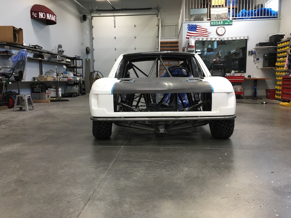
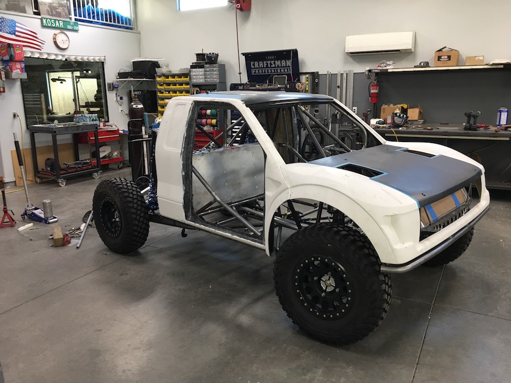
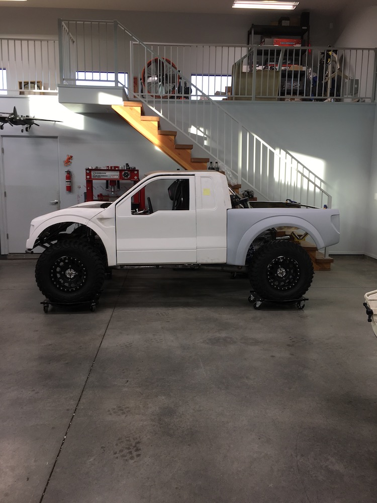
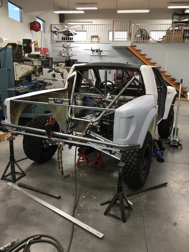
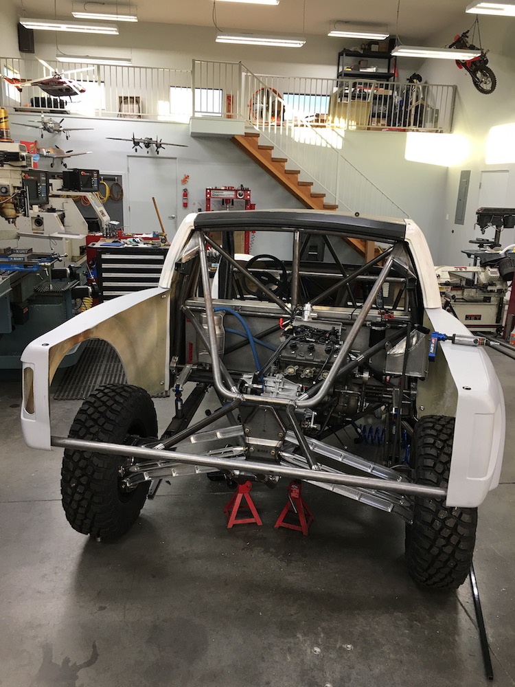
First thing I did today was pull the bodywork and take pics JUST FOR YOU. Happy now? - or at least do you feel a little special?
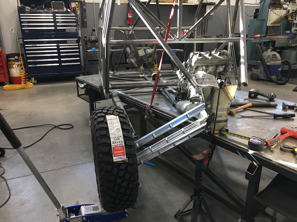
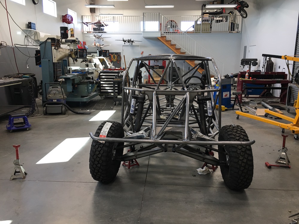
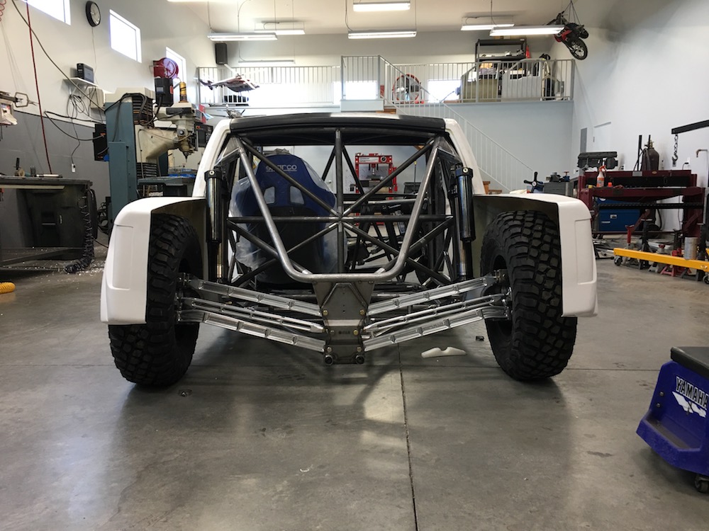
Drivetrain comes out without issues!!!

Ladies and Gentlemen, it comes off the table for the first time! and then over to the bench for a quick weld session on a couple things.
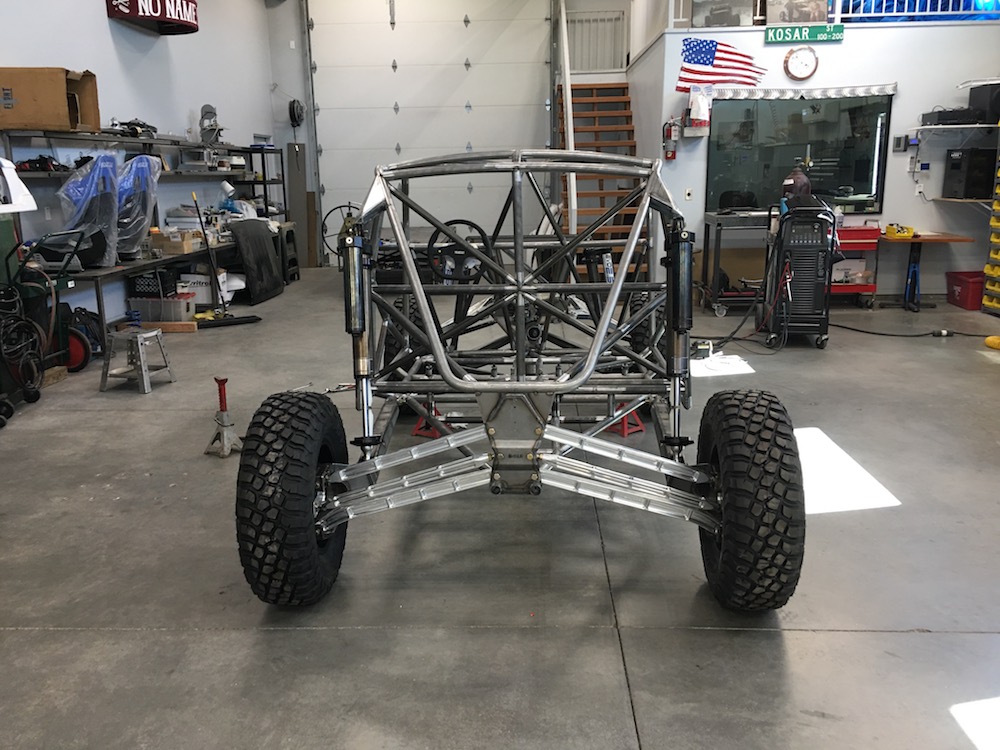
Sitting on jack stands, getting ready for the front end to be put back on:
Ready to drop onto it's own suspension:

Needs a bit of front end adjustment...
Rear view:
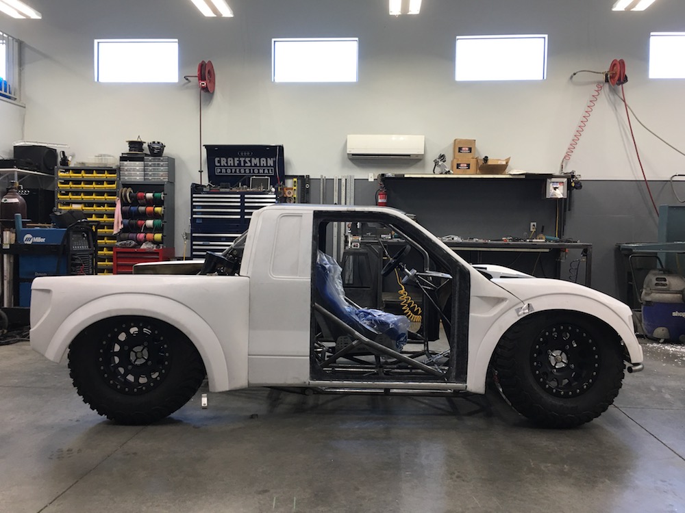
And of course I had to put the body back on (and adjust the front end a bit):
Ride height will probably four to six inches lower than this.
Jun 25, 2018
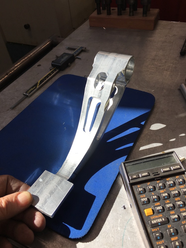
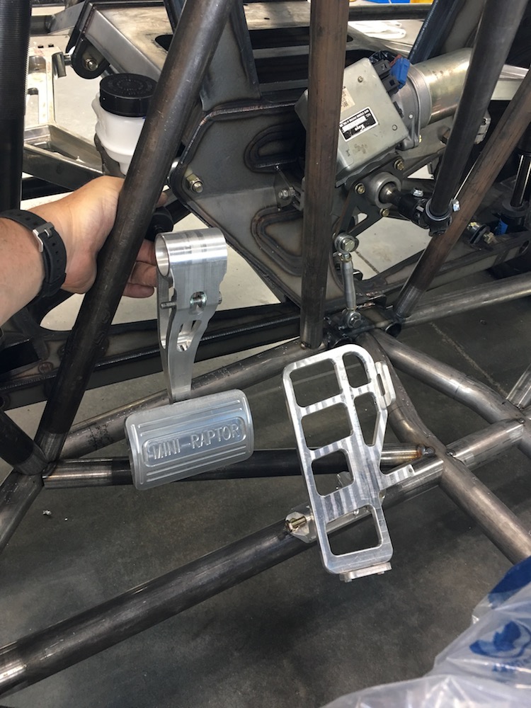
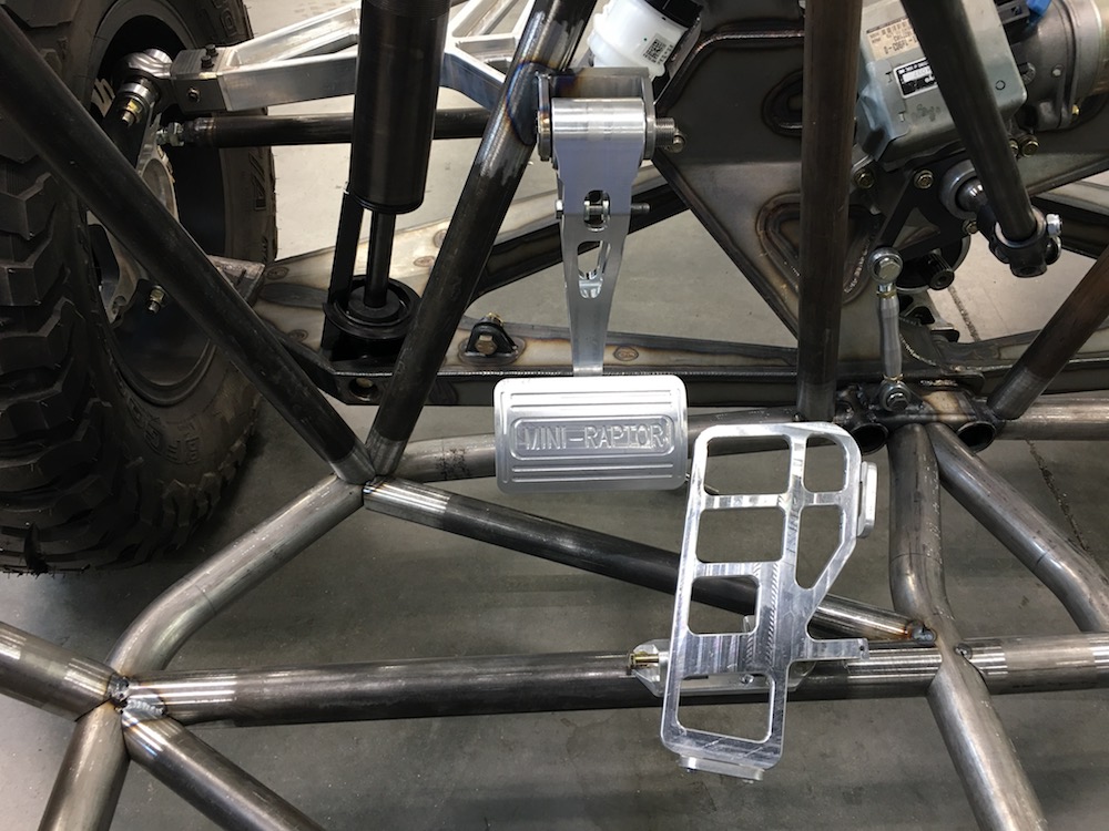
We have a fun pedal!
Pedal and base:

Pedal with the heel and side stays in place:
Side shot - the two bolts are for adjusting throw:
The whole thing assembled:
Bottom of the setup - it fits on the cross bar like a glove.

In it's new home:


There will be an arm that comes off the tab on the right side that will pull the throttle cable. I'll figure out the length of the pull of the throttle cable and then make the arm accordingly.
Ride height:
Brake pedal's next.
Jun 26, 2018
ProtoDie
Pedal looks sweet, like it was designed for flip flops ;)[/QUOTE]They were used as a template a couple of times.
Oh Shit pedal is done. Tomorrow I'll start working on the arm and master cylinder mount.
Hopefully I can have the brake pedal setup installed by Friday - at least that's the goal.
I also got the go pedal mounted - you can see that there's interference between the bolt heads - when it's time to assemble, I'll actually use pins with set screws so everything is flush and out of the way. The long bolt is temporary.
Jun 27, 2018
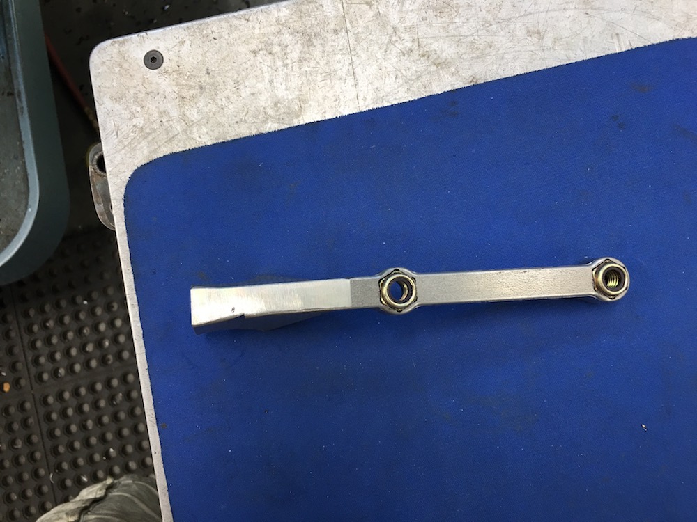
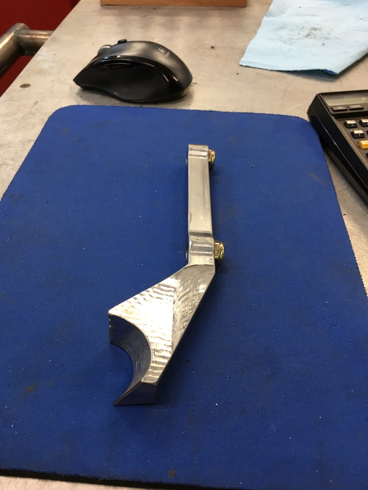
Brake pedal and lever are finished. Next is the master cylinder/pedal mount.
Somewhere deep inside this piece of aluminum is found the ever elusive pedal arm. Care must be taken whilst extracting.
During machining the piece decided to hop out of the vice and make a few laps around a 1/2" ball end mill spinning 5K.
I dropped everything and went running across the room, screaming like a little girl. I don't want to get hit by a 10" long 3x2.5" piece of billet.
It did some cosmetic damage:
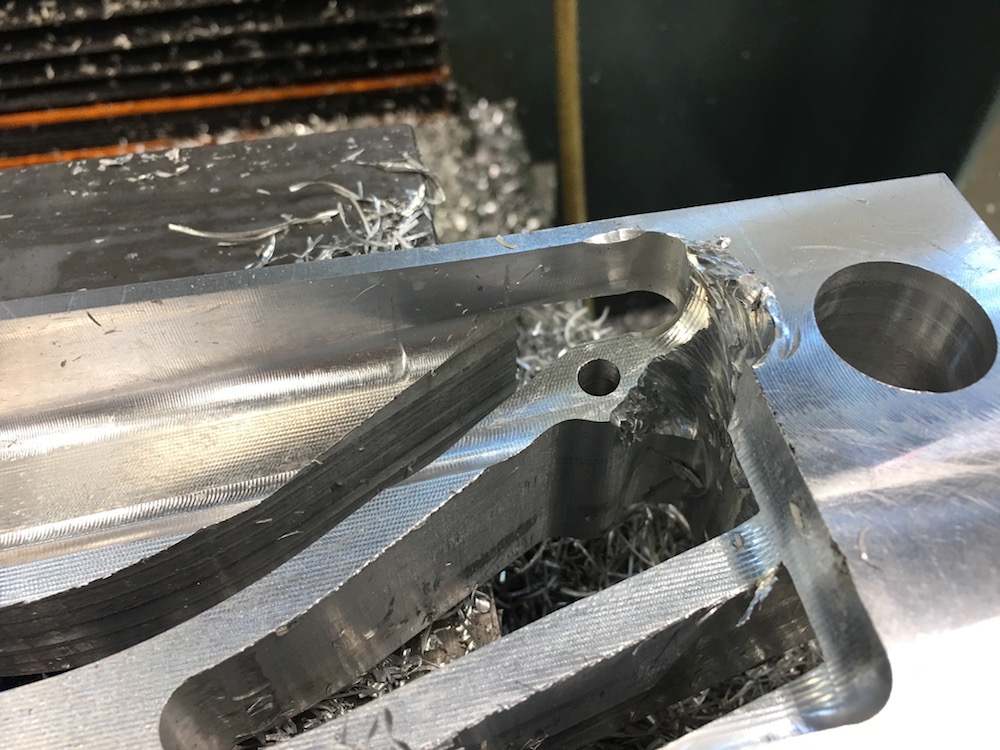
Look at the corner of the piece - and if you look in the background, you can see where it hit the mill.
Like I said, - I don't wanna get hit by that.
The other side of the pedal getting contoured:
Ready to be released from it's former home:
Tada! A pedal!
You can see the bad pass just before the piece jumped out of the vice. I heard it but didn't have time to react - just run.
More holes. Holes are good. - well, unless they're not supposed to be there, like in tires...
Master Cylinder attached:
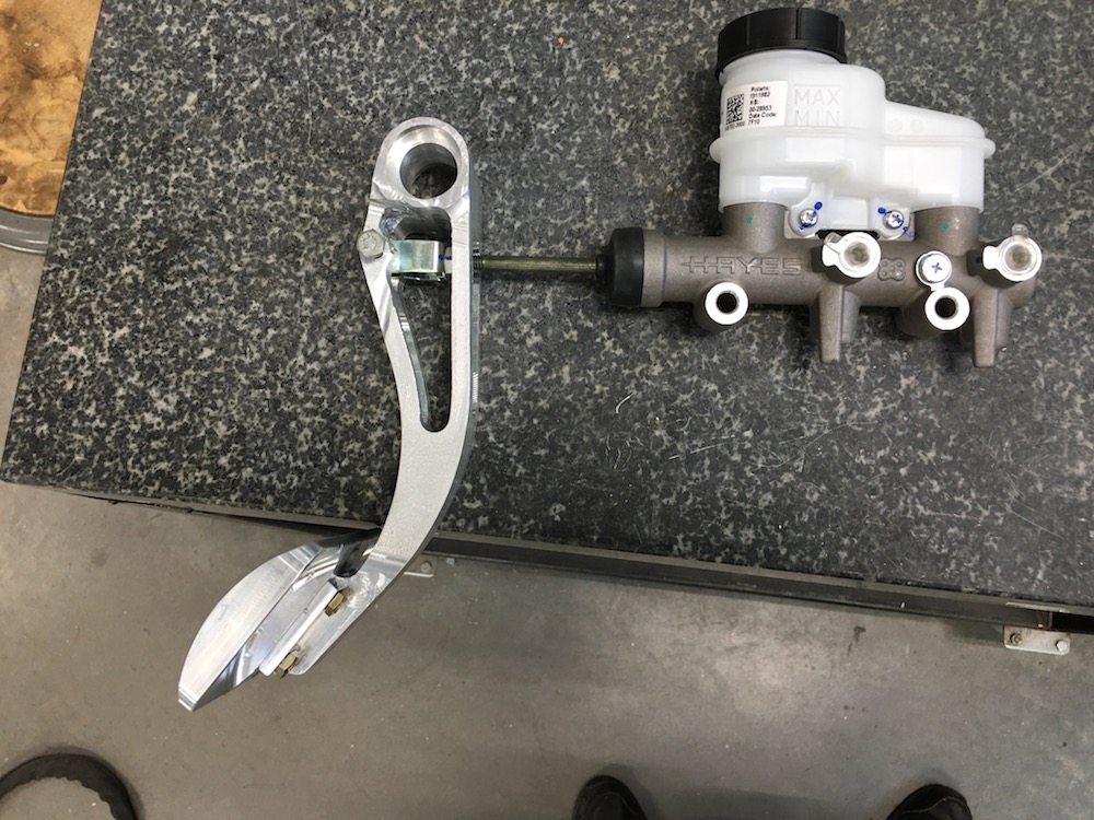
This goes here!
Jun 28, 2018
Dropped:
Pedal arm mount:
Mounting notch:
Pedal goes here(ish):
Mounting notch fits perfectly. Woo hoo!
I have a brake pedal installed!
Jun 29, 2018
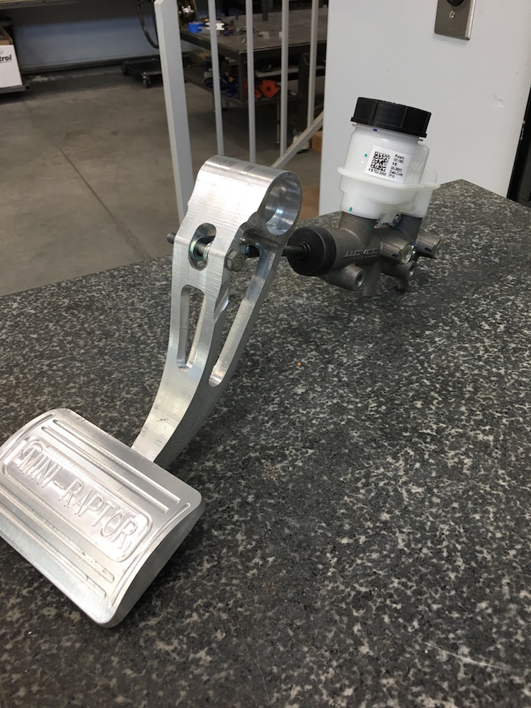
Pedals and brake master cylinder are in place and finished.
I made a stay out of steel for the m/c that attaches to the same tube the brake pedal mount does.

Master Cylinder in place:

Stay mounted:
Pedals all ready to go!

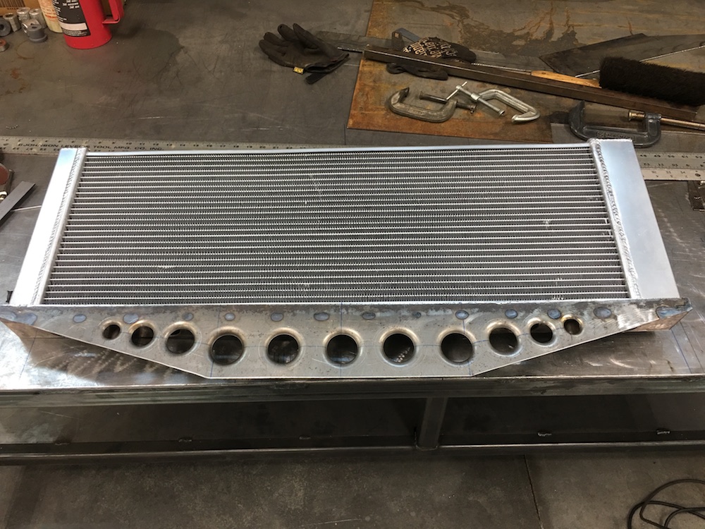
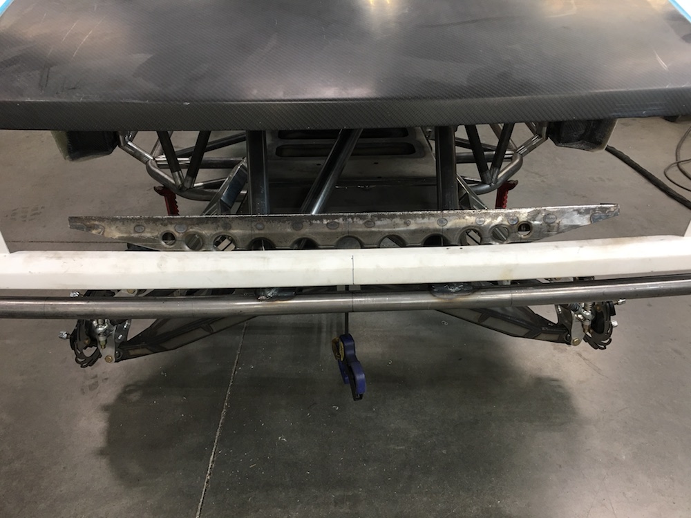
Next I need to get the cab mounted to the cage so I can permanently locate the hood so I can get the radiator redone.
I wasn't happy with the peg mounts in the radiator and will follow advise given to make a cradle that holds the radiator across the bottom.
Once the radiator's in, it'll be drop the engine in and then start on the center console - have to deal with the drive shaft and bring in a parking brake, gear shifter, brake bias bar, seat belt mounts and possibly coolant tubes - not sure on that one yet...
Jul 5, 2018
Parking brake and shifter (temporary piece) in place:
I still have to figure out how to secure the parking brake cable out of harm's way - it's a floppy thing that's right over the top of the drive shaft and that's not good.
Jul 6, 2018
New shift lever with a better feel than the last one (which is in the for sale section if anyone wants it cheap).
For my parking brake cable I went the Wizard Route (he verified what I'd been thinking I'd do). Bent up a piece of tubing, cut it in two (that was fun), cut the bent tubing off the brake cable (that was even more fun! - NOT) and then routed accordingly.
The cable stay bolts to the chassis so if I have to deal with the carrier bearing I'll be able to get to it fairly easily. I made sure that I could get the drive shaft out from between the shifter stay and parking brake mount already.
Jul 7, 2018
Houston, we have a problem.
Windshield is about 3" too long and the main front upper tubes are in the way.
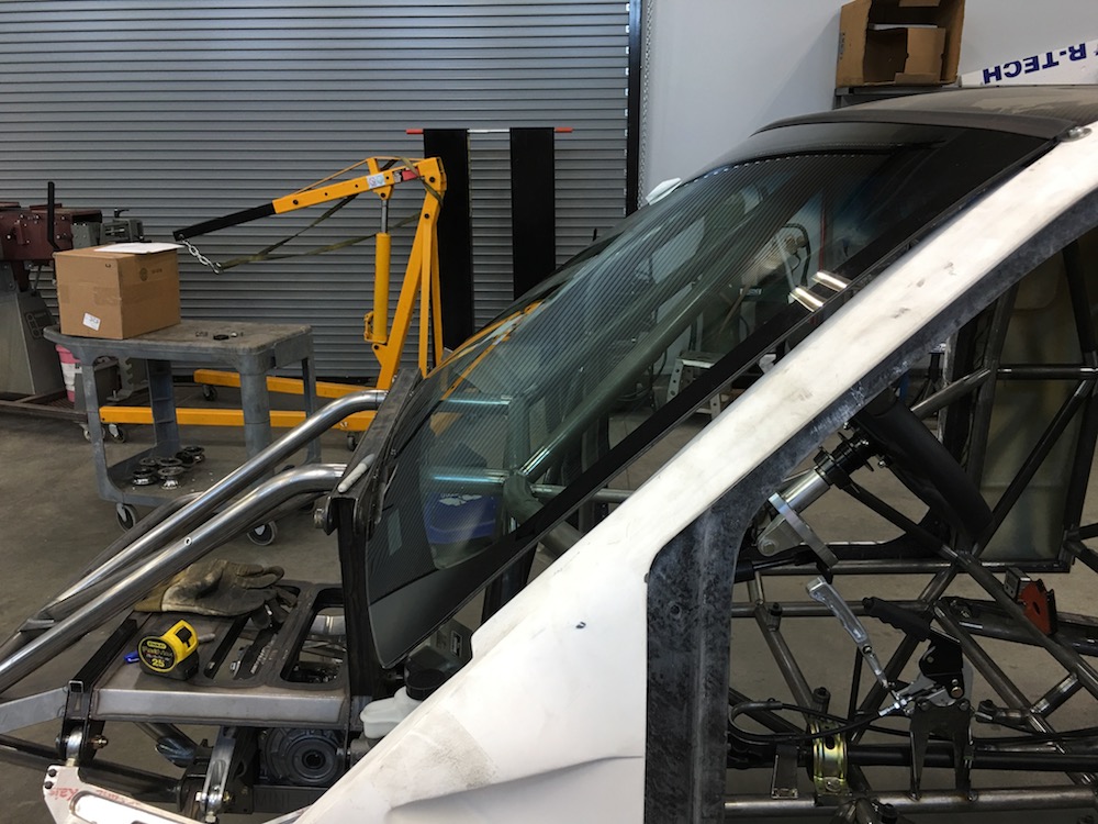
So I get to have the windshield cut to fit. Remove the taped off area and I'm good to go (I hope).
There's a company here in town that can do it so I'll contact them on Monday.
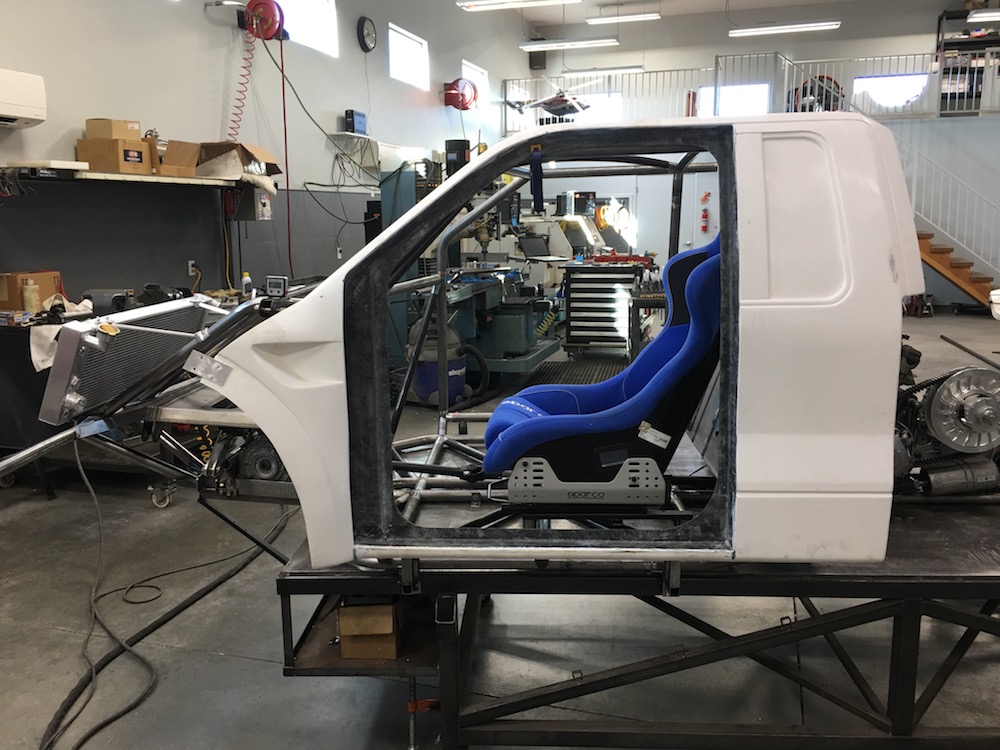
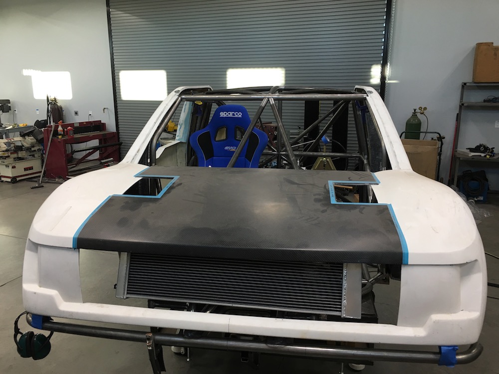
The whole reason for the windshield fitment was to make sure the bodywork is on completely straight - surprisingly it is! Woot woot! So I started getting it permanently mounted.
Started on the front corners, got the mounts figured out, made and installed:

And then made the rear mounts.
The body darned near clips in place now. I still have a couple nut inserts to install that hold the sides in place and now that the roof is mounted I can do that.
Tomorrow I'll get the hood installed. I have a couple ideas I'm tossing around on how to hold it.
Jul 8, 2018
The hood mounting has proceeded to kick my ass. Usually I can see what I want to do/make/ in my mind's eye.
Well... Not today; I have hood block. I do have it set exactly where it's supposed to go, though. TALON shared some really trick mounts with me the other day - I need to go find that bookmark and do a little more research.
I don't have the material for making a radiator mount - time to run to the metal supply tomorrow and see what I can scare up. I need a piece of channel that's wide enough, thin enough, etc. I'm hoping I don't end up having to make the channel but I have a sneaky feeling that I'm gonna...
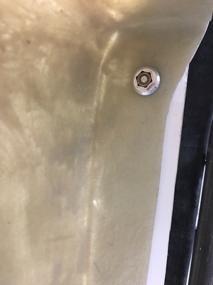
So instead of hood and radiator stuff I decided to tackle one of many little "attention to detail" items. The bed sides mount to the back of the cab sides. I wanted to make sure that I had enough surface support between the two pieces so I whipped out these little guys today:

They space the body panels .150" apart - which is the thickness of the washer in the middle of the top row.

I'm using two per side, upper and lower corners:
July 9, 2018
Hood mounting issues have been covered (thank you TALON!).
It'll be held on with six of these little bad boys from Quik-Latch
:
-----------
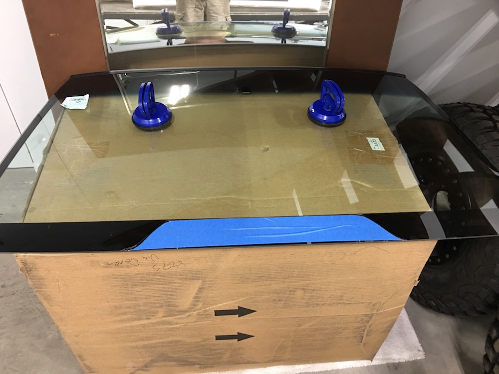
Sitting here on the phone on hold talking to a glass company. My first lead fell through.
And now my second lead falls through "Oh, we can't cut windshields (although we have the ability to cut laminated safety glass), that's a liability issue." Insert swear words...
Three no go...
Fourth one says "50/50 chance of it working, cost is $300 (twice what I paid for the windshield!) and it's not going to last in an off road vehicle." I'll pack up the glass and head that way and hopefully I don't end up with a $450 pile of broken glass held together with a plastic layer.
I think I'll get in touch with Tatum (the off road/sand car makers) and see who they use. (edit - addition) Their place said "Nope!"
Jul 10, 2018
No pics - will post tomorrow.
Glass has been successfully cut and hopefully successfully fit tomorrow. The guy only charged me 170 instead of the quoted 300. Yay me!
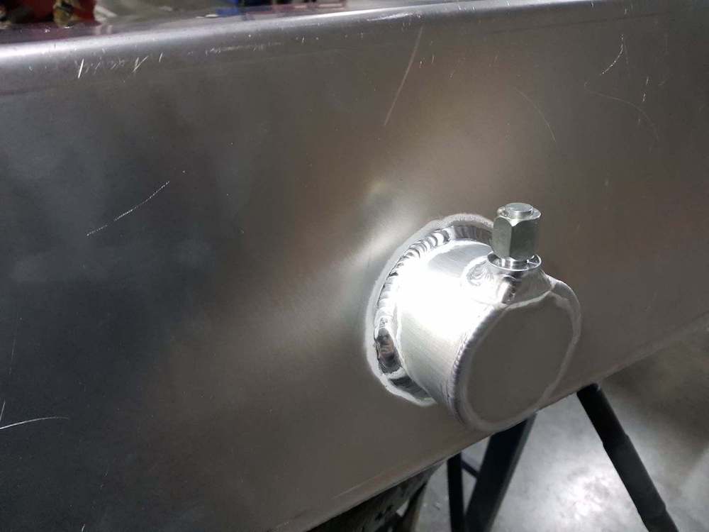
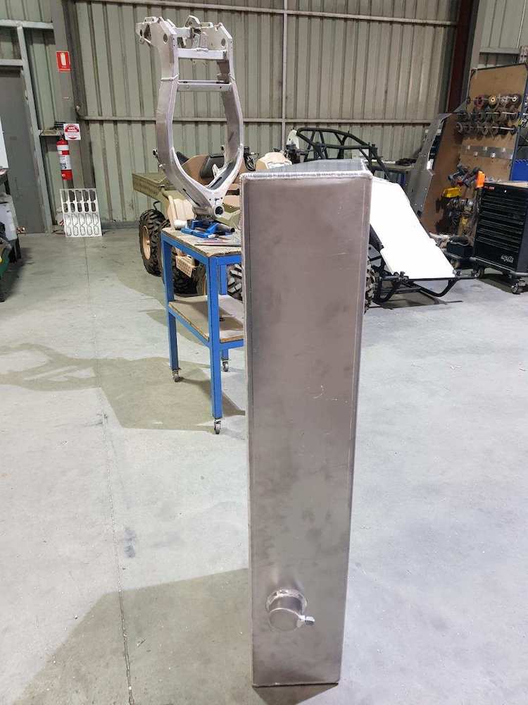
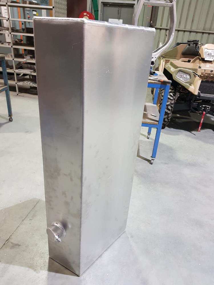
My B&B Off Road Engineering custom fuel tank showed up yesterday evening. It'
s beautiful and perfect.
THANK YOU TALON!
I' ve figured out my radiator mount - got the “shelf” part started and plan on getting the uprights done tomorrow too.
July 11, 2018
Been a great day.
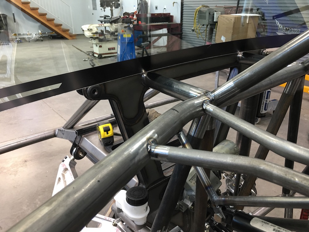
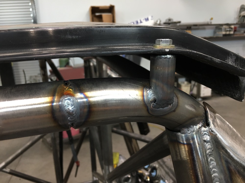
Windshield fits perfectly. I'll be making a lower frame that will tie into the two top main bars. The roof is extremely stiff and mounted solidly. I think it's gonna be good.


Got the body mounts today - must say I'm impressed. Just the two of them hold the hood on impressively well. I'll use six when all is said and done - nothing's moving anywhere.
The fuel tank fits a bit too perfectly - Dumb ass me didn't take into account the amount of angle in the sides of the chassis and while I have an inch at the bottom on each side of the tank, I have "no inch" anywhere at the top. I had to do a little BFH work and notch the tube just a tad to make it a slip fit.
Radiator mount is coming along nicely.

Just for grins - another side shot.
Jul 13, 2018
Lower radiator mount is almost done - still have to add two ears on the ends for a tie down point - this will make more sense when you see it.
Mount in place on the front clip. It bolts in:

Mounts in the tubes:
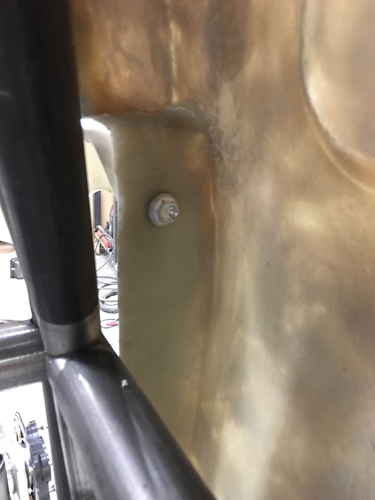
I'm finding it's faster to custom cut tabs and then squish them in the press to the correct diameter than trying to use off the shelf stuff. Makes for a really nice fitting piece. So they sit flush I recess the back side so the head of the insert has a place to go:

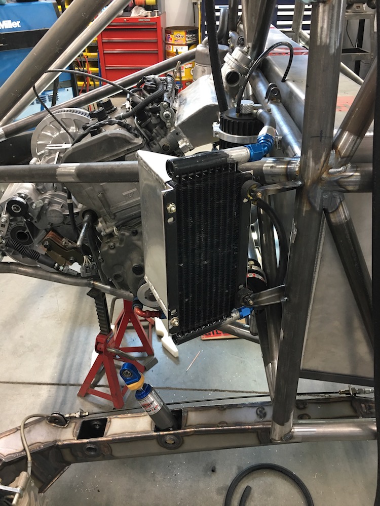
Radiator in place:
Hopefully I'll get the top brackets and hold downs done this weekend.
I get this done and it's time to install the fuel tank and start plumbing.
Jul 14, 2018
Had a good conversation with The Wizard.
Looks like the Mini-Raptor's gonna have Samurai! HVAC, provided it fits and I can figure out how to drive a compressor. The non-existent accessory drive belt is starting to get crowded. Wonder where it's gonna be???
So the radiator mount looked all sweet and such until I put the hood in place. Yeah.. sweet... everything lines up horizontally, like it's supposed to be. Then I decide to take a look from the side. WTF? The driver's side is recessed about an inch at the end of the radiator relative to the other end. AH SHIT. I've mounted it crooked.
So instead of making upper mounts today I cut the tabs off the rad mount, refit everything, put the hood on and off nine hundred and seventy six times, removed, installed, moved the rad one thousand six hundred and three times, cutting, grinding, swearing and now the damn thing is straight and square with new mounting tabs. There's a wasted afternoon!
There's a theme here of redoing things at least twice. I'd like this theme to stop.
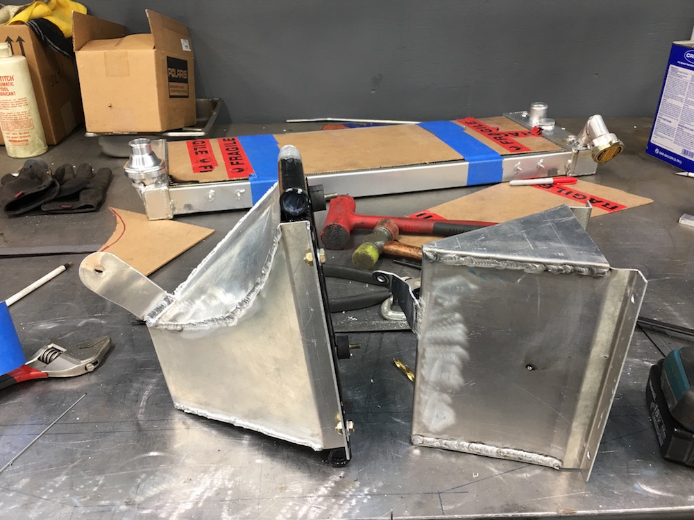
I'm still sticking with my original idea for an upper rad mount/stabilizer but I've added stuff so it's all held in place.The radiator sits in the lower mount, still uses the locating pins, will have foam like a mouse pad under the tanks where it's supported. The top is now held down with a pinch clamp setup so the radiator can't hop out and then I went to the original diagonal tube braces idea to keep the thing from flopping around.Got smart(er) this time - making one side at a time since the radiator doesn't seem to have ANY symmetry.
Driver's side is done:
Jul 17, 2018
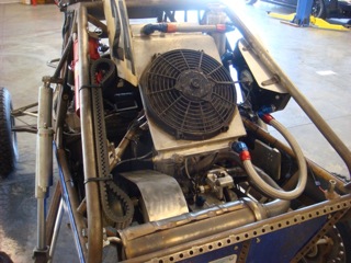
Radiator is installed both straight and level.
Fuel tank is now finding it's home:

Deranged
SWEET!! The speaker box fuel cell! The ole Rorty car had one just like it.
Me
AH HAHAHAHAHA!!! I need to draw two 16" speakers on it. - hmmm.... I know a guy that has a vinyl cutter.
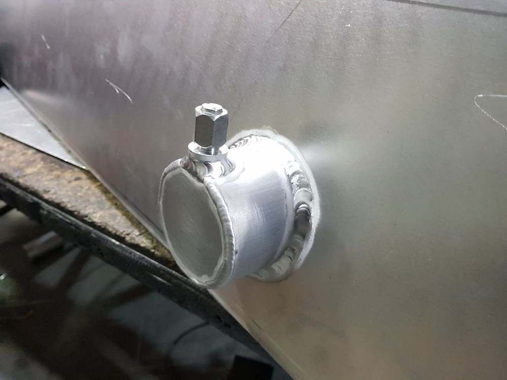
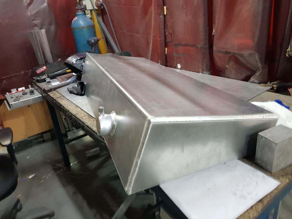
Speaking of the fuel tank, it's in.
Upper tank mounts - and of course one side has a nut capture.
My TIG welding is getting better:
Here's the bottom mount - and yeah, there's a nut capture in the bottom piece. I'm obsessed with the silly things.
So far the only time I'm going to need two wrenches is on the steering tabs - and I keep thinking "I could make a little piece that fits over the finger and holds the nut." It's a goal to use one wrench on any fastener on this ride.
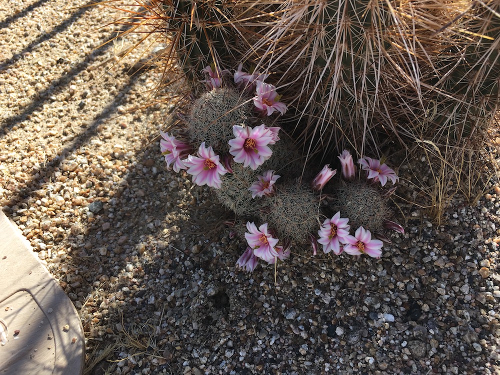
Cactus is blooming - figured I'd throw it up just 'cause it's purty.
Jul 19, 2018
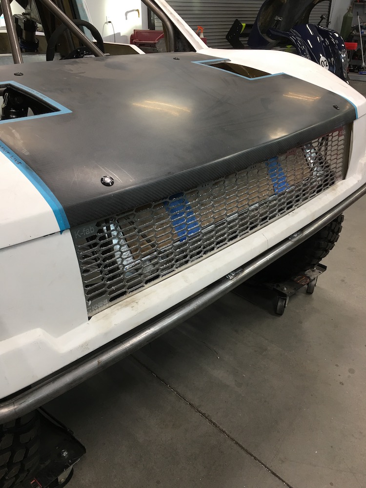
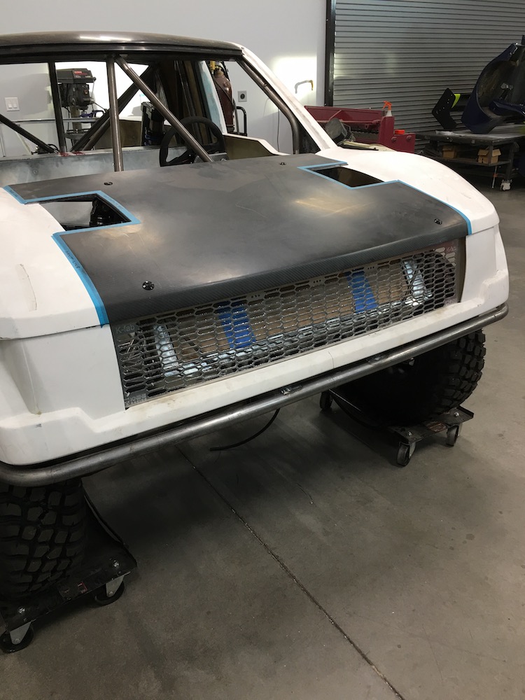
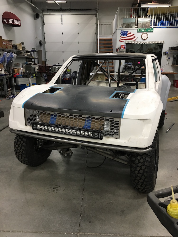
Radiator mount is complete along with the hood mounts:
The hood doesn't move at all. I can't believe how solidly these little Quik-Latches hold things in place.
Came to the realization yesterday that I have all the major components mounted and in place! It's plumbing, wire and then start in on the dash and interior work. There really is a light at the end of the tunnel. WOO HOO!!!
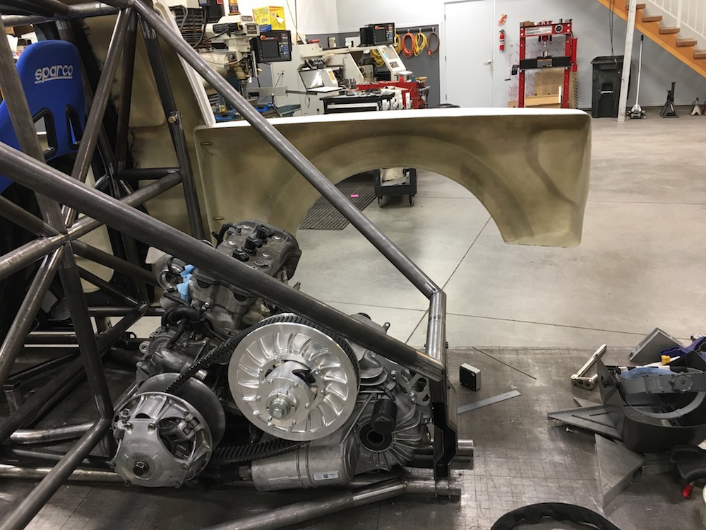
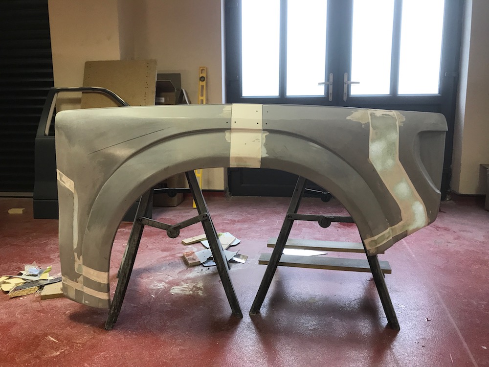
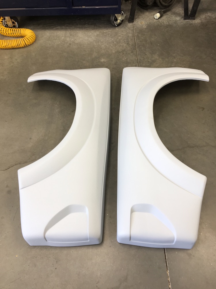
The fenders went out yesterday for some work. They'll be split in the middle of the arch and have 2" added to center the wheels a bit better and the back is getting stretched 4".
Here's an example that Benihana sent me:
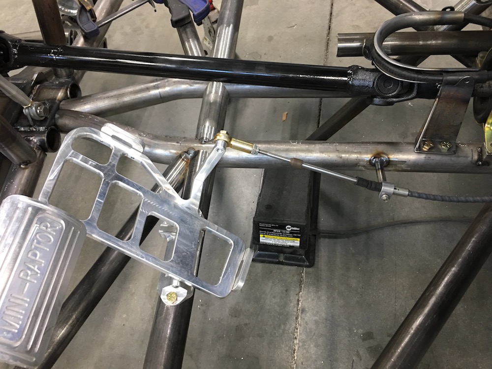
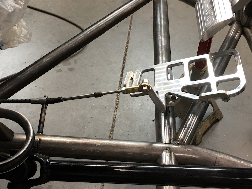
I got the throttle cable installed this morning (been up since 4:30 - the harder I tried to go back to sleep the more awake I was. Oh the fun....)
Jul 20, 2018
I've done a bunch of that today.
Throttle pedal is done, complete, finito. I actually had a cable (think it may have been a Briggs or original Deztaz) and it works. It's about six inches too long, so I'll go get one made that's correct but at least I was able to get the throttle done.

Then spent the rest of the day fitting stuff and figuring out where things are going. I have to run two coolant lines down the center. Easiest (maybe) way would be use the two center tubes. Block them off on the ends, install fittings and there you have it. BUT to block them off I'd have to cut them in two at the ends and then weld in a round plate that would seal everything. Not really liking the idea of cutting and welding the tube x 4...
I'm thinking an aluminum tube down each side of the center stuff and then wrap them with insulation and hide them under the center console. It makes the console wider at the bottom but it gives me room. Dunno...
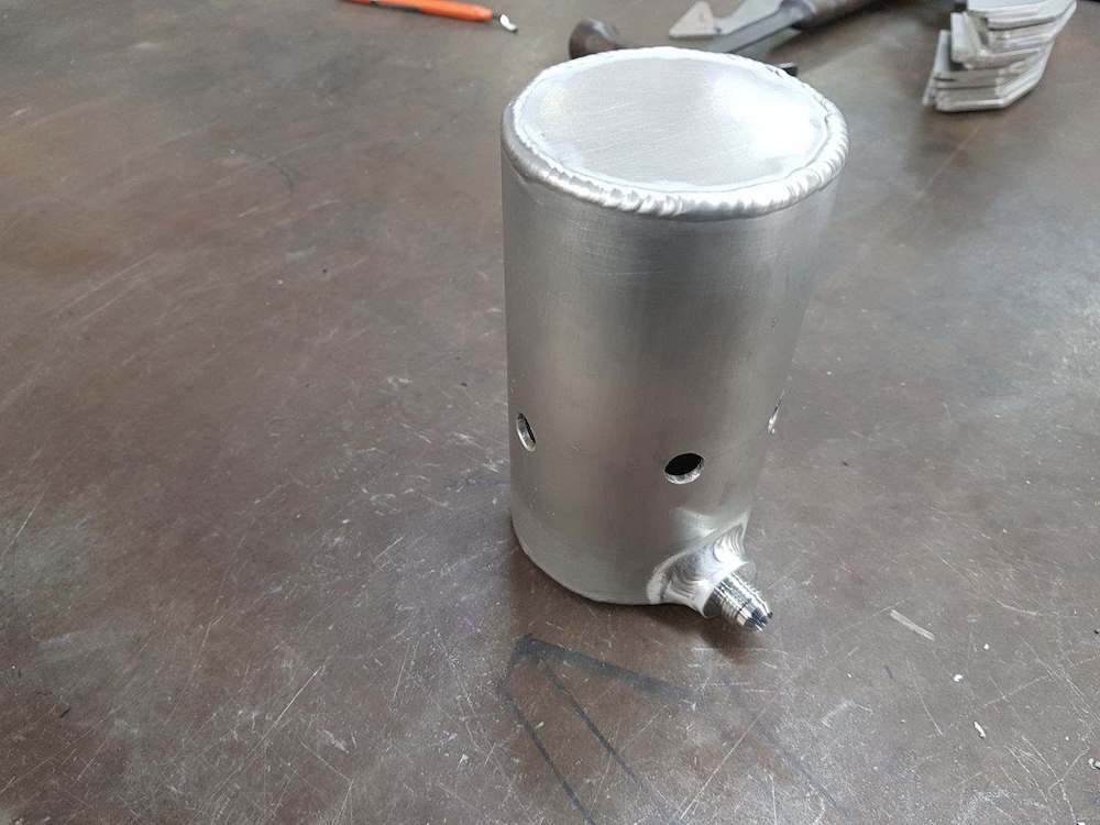
So I pulled out some of the other things that have to get installed and worked on them. Got the coolant and oil res's mounted by the end of the day.
Of course the coolant res's mount has nuuuuuuut pockets!


Mounted:

Yamaha's OEM oil tank. It has baffles and such in it so I want to keep it - did this with the Briggs. This one's gonna get powder coated, though. I'll probably have to move the fittings around - or get creative. This silly vehicle's already over the top so I'll do stainless lines with AN fittings on everything I can. I can probably weld them onto the can (or get someone that can actually do detailed aluminum TIG welding to do it for me... Hey Jay!).


I've gotta get my coolant system plumbing figured out...
July 21, 2018
Spent the better part of the day playing with tubing and trying to figure out where to put stuff.
Fortunately I realized that I'd put the oil tank right in the middle of the sway bar mount before I got too far. The bar was only tacked in so...
Now the tank is on the other side, above the sway bar and there's room for the reservoir for the supercharger next to it. Plumbing is partially responsible for placement too.
vI have a dilemma: Where do I put the supercharger's radiator? I don't think I want to fight with getting it up front. It's about 5x11 and it would be easy enough to put a fan on it. With a fan, will that keep it cool enough? I'm just not sure where to put it.Thoughts anyone? Getting it up into airflow is going to be an issue...
Maybe I can do like I did on the Briggs - radiator on the down tube, scoop to bring air over it.
Yeah, that may work. - figured this out as I sit here typing...
Jul 25, 2018
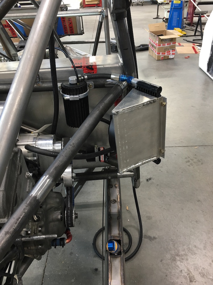
Supercharger's cooling system is mounted and ready.
The radiator sits inside the fender, tucked up near the back of the cab. I'll be making a shroud that puts the fan more or less parallel to the wheel so stuff from the wheel doesn't get into the system.
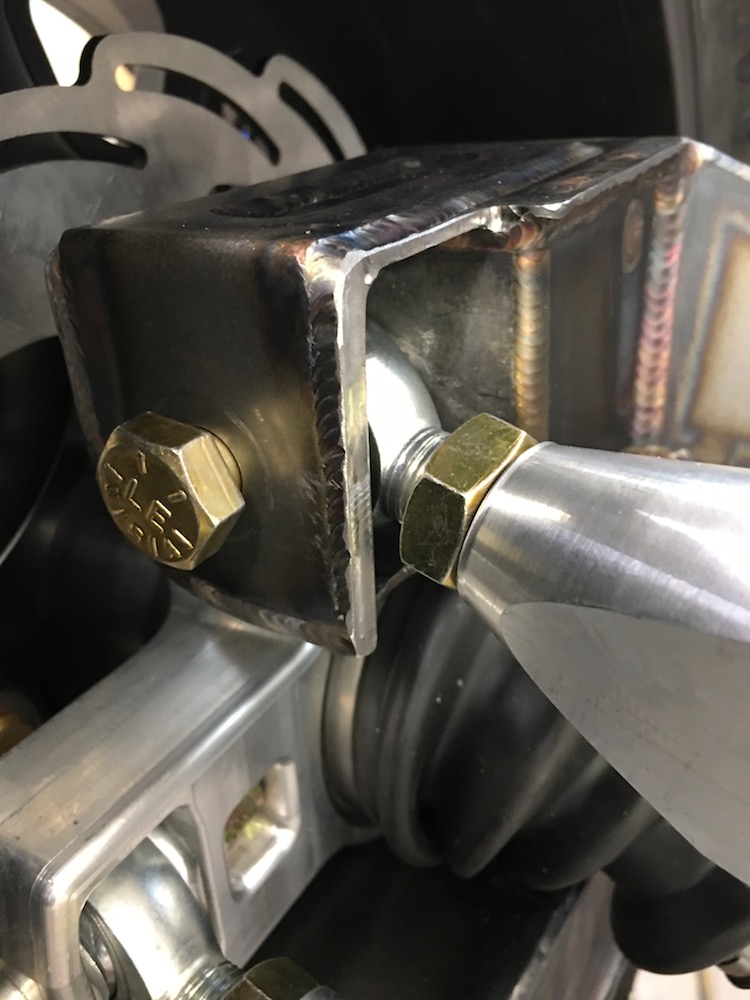
Been working on mounting brake lines today too. I have the hard lines run on the swing arms and lower front arms. Did the braided lines from the calipers to the hard lines too - and no finger pokes! I have to go get more hard line (had to order from NAPA) tomorrow so I can run the chassis lines.
Also picked up some 1.25x.065 aluminum tubing so I can start making the cooling lines. I see more NAPA trips for hoses - they had a huge selection of funky bends so I think I'll be able to find what I need there.
Fuel system will get tackled next - have to pull the engine/trans to get the nut inserts installed in the frame - will give me a chance to cut the back wall and fit it too.
Ah the little things - lots and lots of little things... This is the time consuming stuff.
Aug 5, 2018
Brake lines are all installed - ready to be taken apart when I pull everything apart.
Still wrapping my head around cooling lines - have tubing, need some more "study time" with it.
Got the supercharger radiator's shroud and fan done. I SUCK welding aluminium. I tried to channel my inner TALON but alas, I wasn't in touch...
Fortunately it's hidden in the fender so nobody will see just how badly I've melted everything together.
Suzuki Samari! blower - not sure how this is gonna work... I see duct work (oh fun) in my future, maybe. Don't know where I'm gonna put the heater box.
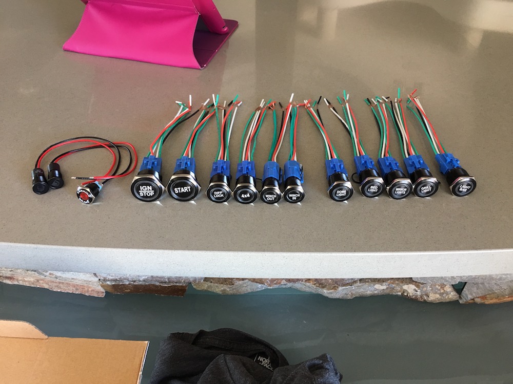
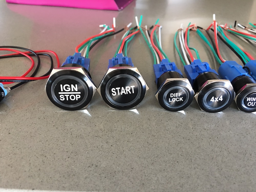
I also got my buttons! Ordered from Billet Automotive Buttons, down under. Killer quality, service and such. I'm impressed across the board with them.
Aug 7, 2018
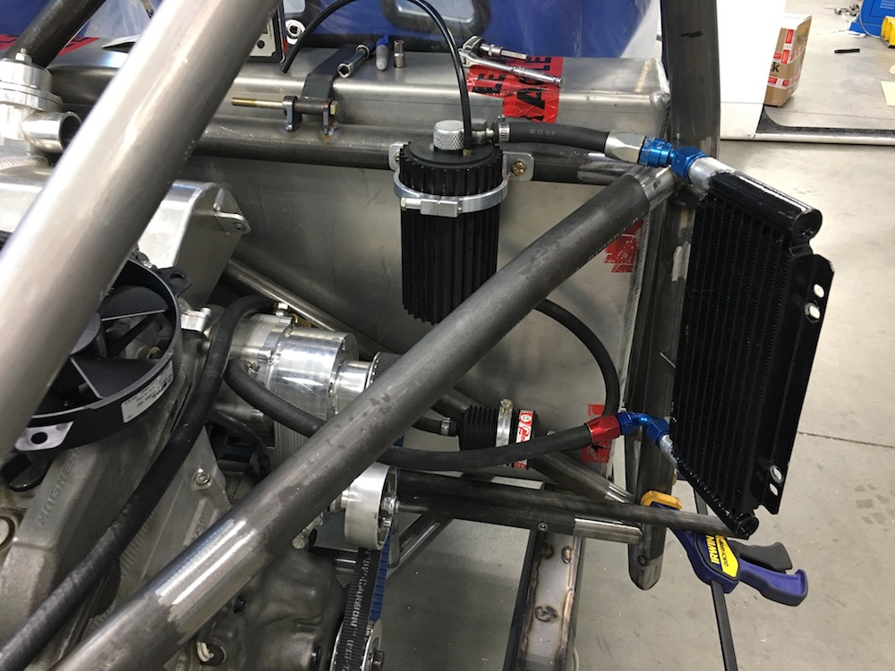
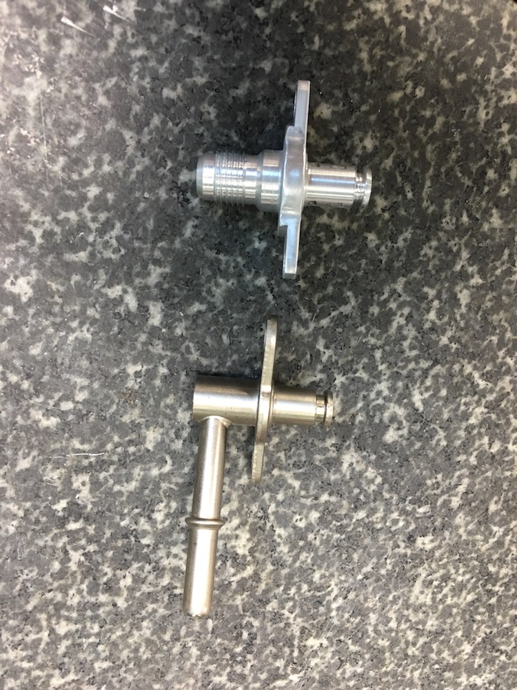
The MPI kit changes the water output from stock; they have the water coming out of the right side of the engine. There's also a throttle body warming circuit, a bypass that feeds water through the water/oil cooler and a temp sensor in their little manifold:
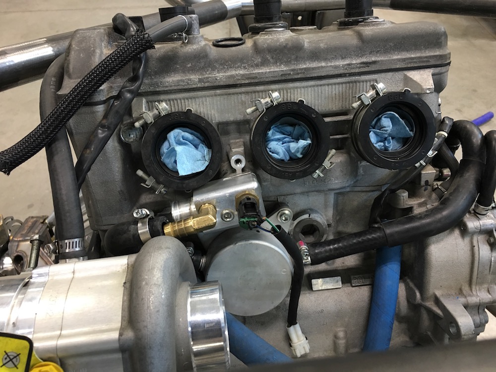
Not much about it was correct for this setup so I made a new one. Got rid of the throttle body heater circuit, made the water/oil line more direct and placed the temp sensor out of the way of everything and pointed the outlet down so I can plumb to it:
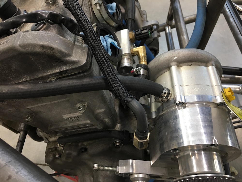
Got the transfer tubes in place (more or less). They'll get welded together and then put on mounts so they aren't up against anything. I want to be able to run some sort of insulation blanket around them too when it's all said and done.
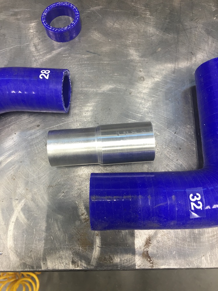
Time to get on the 'net and find silicon toooobing and elbows and stuff. I like the SFS tubing I have so that's what I'll get more of. Done a bit of searching and they offer a bunch of elbows and things I need. Cooling's moving along.
Aug 8, 2018
All my cooling system elbows, connectors and reducers have been secured. Shipping in two to three weeks - which actually works out as I' ll be taking a three week hiatus starting Sunday; have a multi-state “tour” with my better half to escape the summer heat.
The bed side mods will be done by then and hopefully I' ll see axles, my dashboard and associated sensors and such too.
I got some really pretty beads laid down yesterday - right up to the point of dabbing the tungsten... Seat time, just need more seat time.
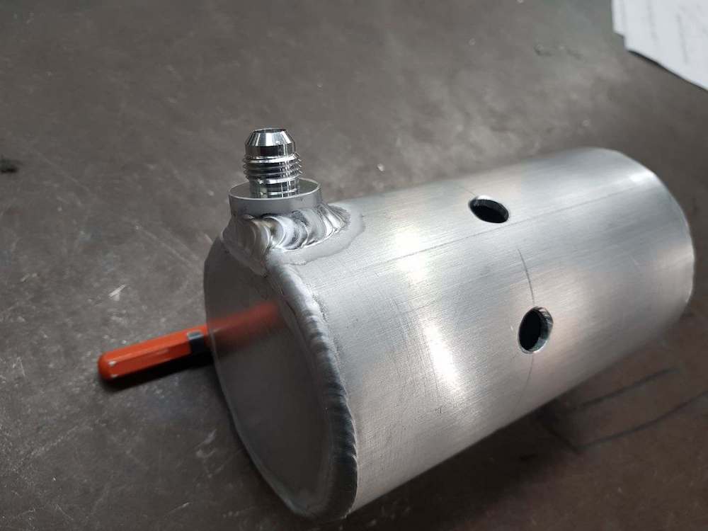
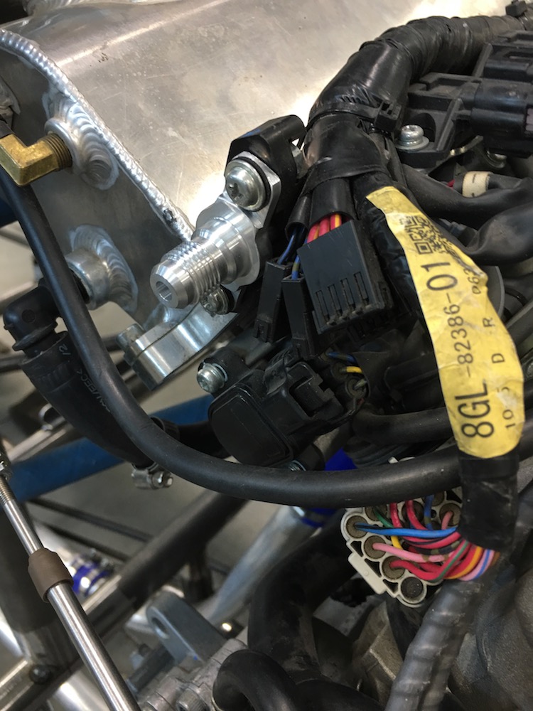
Made fittings today - learned, with a little internet searching, that AN fittings are a 37 degree cone. The magic number...
The Yamaha fuel rail has one of those clip on fuel leads and it's pointed in the wrong direction.
So I made a new input that's -6 AN so I can plumb away:
I'm now trying to figure out where the Donaldson air filter's gonna go. It's 16" long, 8" in diameter and that's almost exactly the size of the hole under the throttle bodies, behind the bed and... argh,,, gonna have to cut off an engine tab (you can see it in the picture above). I have two cans of paint taped together and they're pretty close in size to the Donaldson and they don't fit very well, yet.
I need to either figure out how to make it fit down there or it's going to end up above the clutches and hopefully not sticking out of the bed. I think I can make it fit. There may be some divots required in the canister and I'm not sure about the intake's placement. Need to get one in hand.
Also worked on the fuel system - I think the pump and regulator are going to get mounted to the bottom of the tank - is it okay to have the return line in the bottom of it? I can't see any reason why it would be an issue but I'm hoping if it is someone will chime in before I go welding bungs to the bottom of the tank.
Sep 5, 2018
Howdy all, I'm back.
Spent the past three weeks putting 6K miles on the pickup and trailer to escape the summer heat (for the record, I'm good with the temps - I just go into my shop and work. The wife, on the other hand, well... you know, they run the show so we went on vacation.)
I must say that if you've never been to the Black Hills in South Dakota and Yellowstone MAKE IT A POINT TO GO! Wow, just wow.
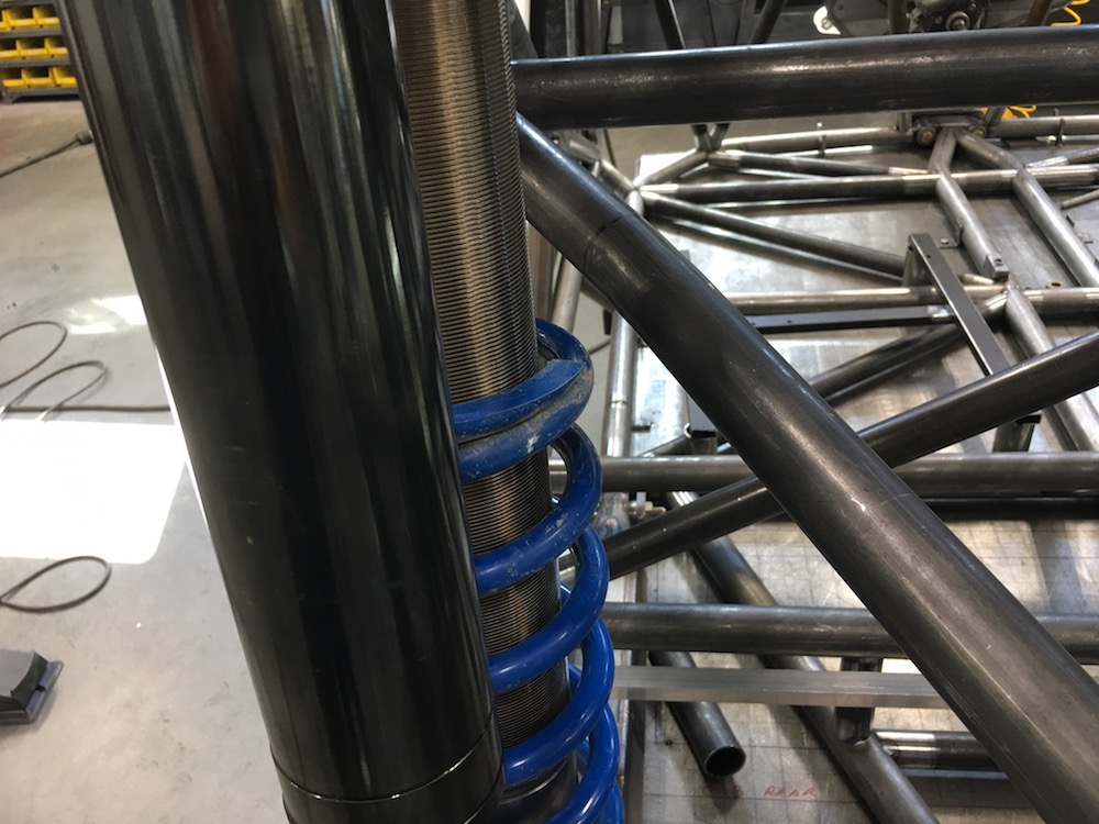
Got the sway bar mounts made and placed:
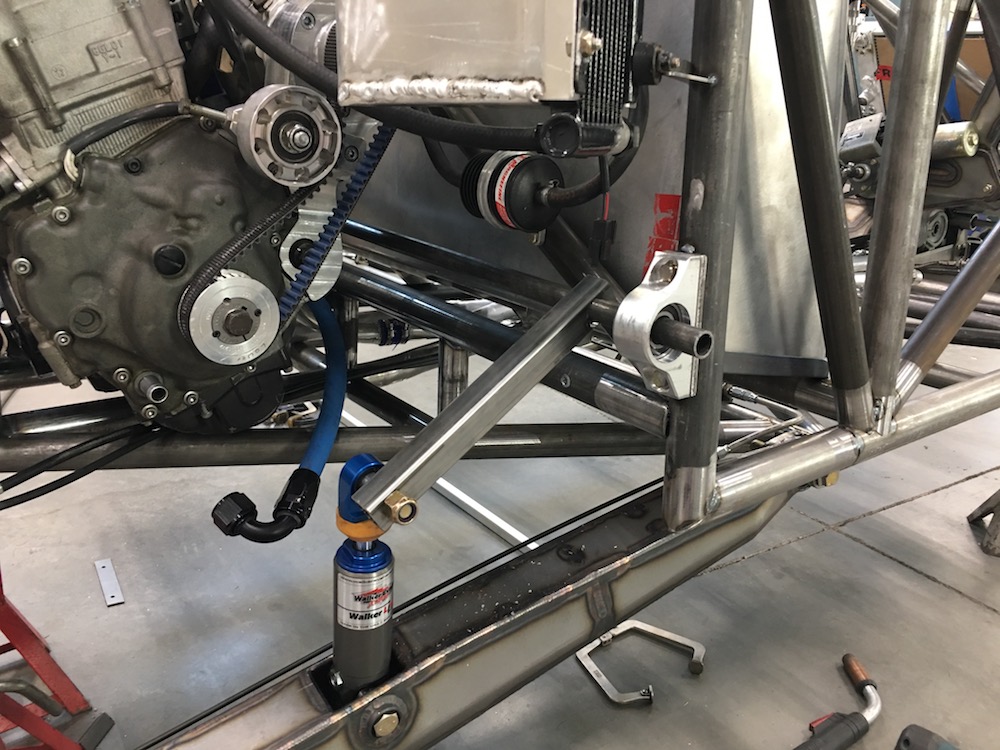


Yes, the bearings are parallel... (because I know the wizard's gonna say something about it)
Sep 14, 2018
Haven't had much of a chance to do anything this past week.
I did discover one really crappy thing yesterday, though.
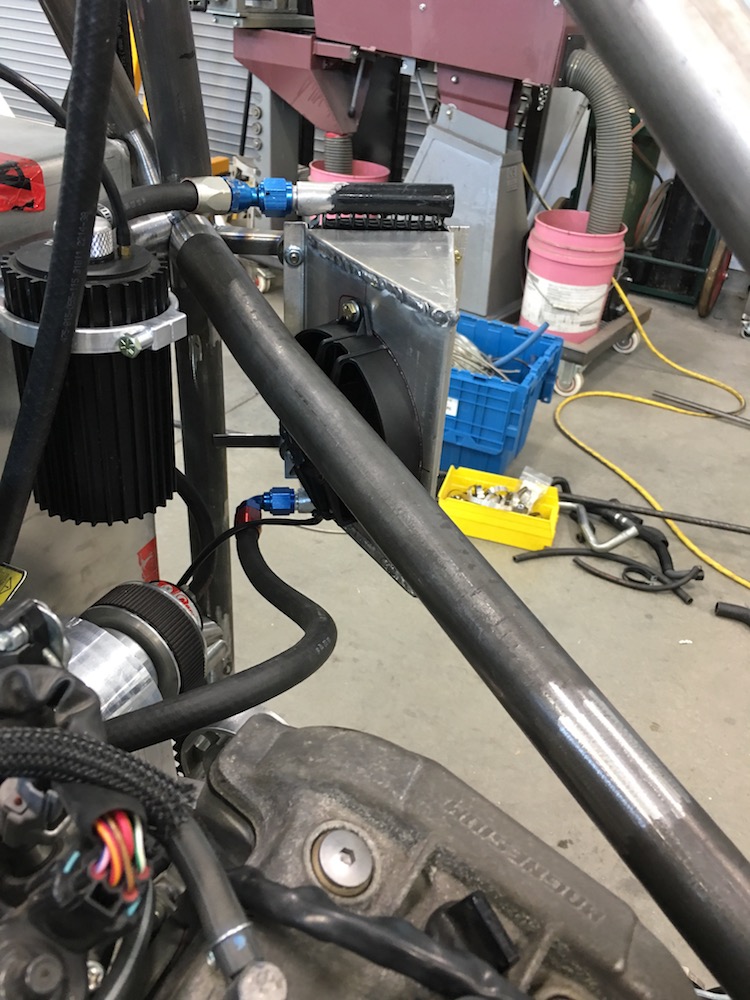
Was standing by the Raptor and looking at the shock mount on the passenger's side. Hmmm... If I put the shock back on it would appear that the supercharger's cooler shroud may be in the way. So I grabbed the shock, heaved it into place and then started swearing. Yup, the shock goes right through the top/back of the shroud. SHIT.
I'll be making a new one.
Three steps forward, two back, fall down, get up, two steps forward, one back... This project is a pain in the ass.
Sep 16, 2018
I spent yesterday making a new one.
It still has to have the mounts on the chassis modded - moved forward 6mm or so.
Here's a couple shots of the two boxes - the original boxy one and the new swoopy one. My welding improved majorly - discovered that the cooling line was plugged and also moved down in wire size. The new box is also just two pieces. I took the time to fold it all up and only have one seam on the single piece and then the curved cap that goes by the shock body.
I'd planned on working on things today but alas, I bailed over the bars of the bike this morning and have been reminded just how much I don't like having my breath knocked out. Don't think I broke any but the bottom two ribs on my left side sure like to let me know they're pissed at me for slamming them into the rocks. Ouch...
Been driving the couch all day instead.
Sep 26, 2018
In response to the crashing I have a tale to tell:
I've been due; not crashed in quite a while... Knew it was coming eventually.
Broken ribs suck
Got pitched off middle 3rd gear last Sunday 10 days ago.
Landed in some short bushes that were concealing a of couple large rocks and finished it off by sliding into an elk horn (thank god!) cholla. If you're gonna hit a cholla it's the one.
Jumped up (adrenaline is good!) realized I was getting ready to loose my breath so I took a deep one, bent over and grabbed my knees and held my breath as hard as I could. It worked pretty well. Didn't do the scary all my air is gone thing.
Pulled a couple dozen thorns outta my arm, side & leg and the rode off. About 30 min later I realized the pain was starting to break my concentration (went down two more times - both low speed cause I was getting sloppy).
Stopped and had a conversation with a rattlesnake and decided it was a day.
I got home and sat down on the couch and started getting spasms. Oh the joy! This past week has sucked.
Yesterday morning as I'm laying there pushing the tender spots and breathing deeply I can hear and feel "pop, pop". Not good can feel the broken end of one.
Kinda figured I'd at least bruised my side and x-rays today verified breaks in #9 & 10. Really easy to see the gap between the ends.
What makes it even better is the radiologist's comment about how #5 & 7 both showed signs of previous fracture. Yeah, ribs suck.
I'm still not too old for this shit!
Got the sway bar arms designed x hope to start working on them tomorrow.
Oct 6, 2018
Tomorrow will be three weeks since "touch down". I'm finally able to get back into the shop (and we've had company the past week).
Sway bar links and mounts are done. I still am not sure what I'll be doing for the actual torsion bar part of this assembly so I've left the pieces the links press onto fairly large so I have material to machine/weld to/do what ever happens...
Oct 15, 2018
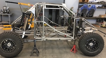
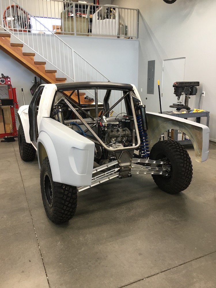
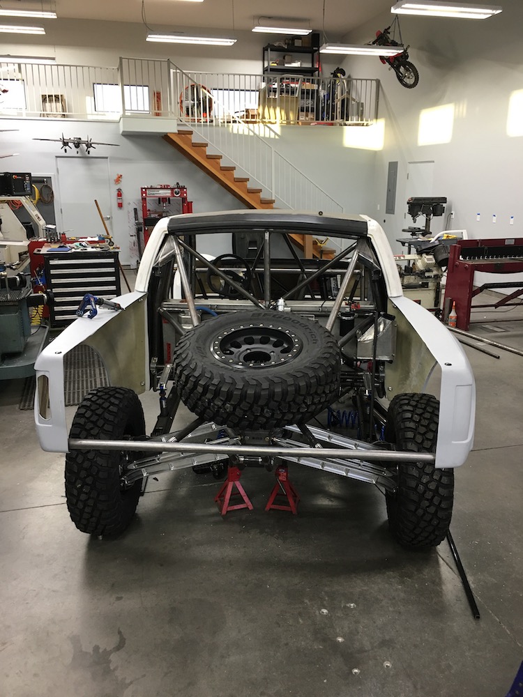
We have a roller!
Tossed springs that I had onto the shocks (rears are extremely stiff, fronts are single springs but in the ball park) and decided to see if it would hold itself up (no tack welds have popped yet) and how easily it rolls. I needed mobility for a good shop cleaning and some KTM prep.
It sits at least 2" too tall in ride height presently but that will all change with the correct springs.


Still waiting on the bedsides (supposed to have been done a couple of weeks ago but the guy's been slammed), plumbing (elbows, reducers, etc.) and all the stuff from Knine (axles, dash electronics, sensors and crap).
Once I get the bedsides back I'll be able to start doing the rear framing and exhaust.
So close...
Nov 28, 2018
I finally got the bed sides back so I can start the rear frame/support section.
Plumbing elbows and connectors are still lost in customs somewhere.
Axles and electronics are not here yet.
My present interest in this project is 0%, my frustration level with the whole thing is 80%.
Honestly, if someone were willing to give me 25k (probably less than half what's been spent on it) I'd send it right out the door...
It'll get finished eventually, though.
Dec 8, 2018
Part of my "writer's block" is waiting on plumbing and some other stuff.
I ordered a bunch of elbows and connectors and such out of England back in August. Was informed that it would be a six week wait (things are custom made). I was in to the tune of $271.78 in the silicon pieces.
Got a phone call from UPS customs:
"You owe us $807 and change import duty."
WTF??? How can I owe three times what the parts cost???
So we began tracking invoices and such and it turns out that someone missed a decimal point and I was being charged import taxes for $27,178.00.
Uh NO!!!
I'm still in limbo with UPS, Customs and have no clue where my box of blue silicon hoses is. I've called quite a few times and I get the same "You're in the cue. We'll be in touch when we've gotten to your stuff."
Shit.
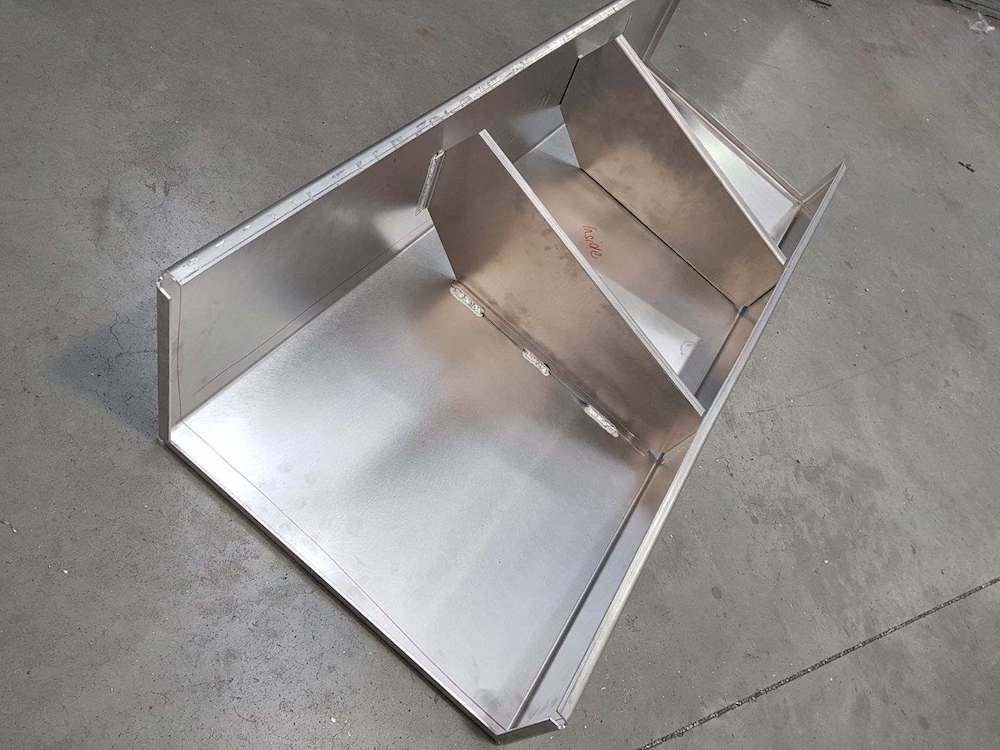
I was also on hold waiting for (another "I can do that in six weeks" that turned into two and a half months) aspect - I had the bed sides stretched; 2" in the fender well and then another four inches to the back, in front of the tail lights. They came out sweet and were worth the wait.


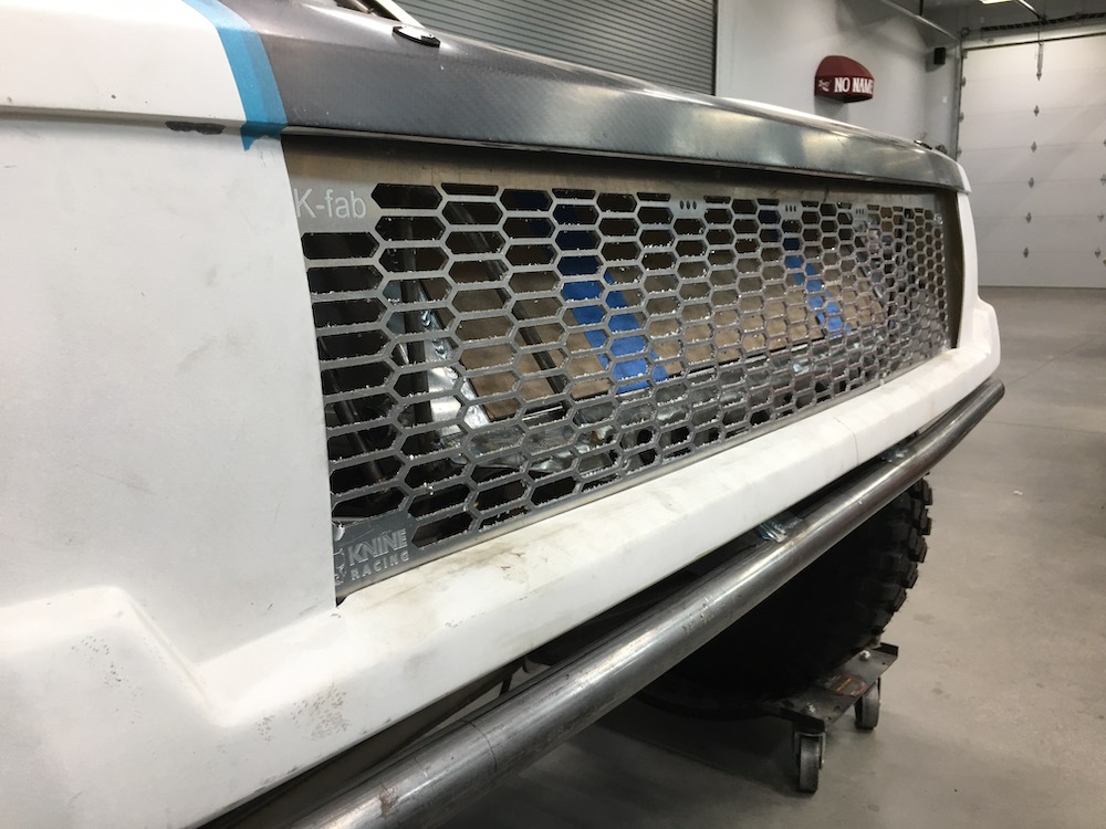
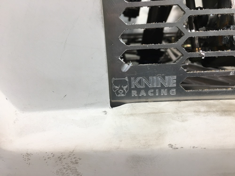
I also got the grill cut out (another month long fiasco). The fuzzies you see are chips stuck to the adhesive. I still need to clean it all up:

Benihana is supposed to be on the way to the States in a few days and will have all my electronics, lenses for lights and some other stuff. Once I get all my shit together and gathered up I'll start working away on the Mini-Raptor again. I do need to go ahead and start getting the back subframe done, though and I have at least a week's worth of welding on the chassis so I definitely have work to do. Gotta go get welding gas - all my bottles are fluffed.
--------
My focus on other things has also taken a bit of a turn for a while - half the bodywork is in a couple of the pix. I'll wait for Bull to call it out...
Dec 12, 2018
Started working on the bedsides - getting them in place, making the rear sub section and such.
Had to find out where the rear tail lights fit in the grand scheme of things before I start putting tubes all over the place.
These are Rigid Chase Lights - six functions: Tail, brake, signal, strobe, reverse and it also has a bed light in the side. We have them on our XP41K and they work really well.
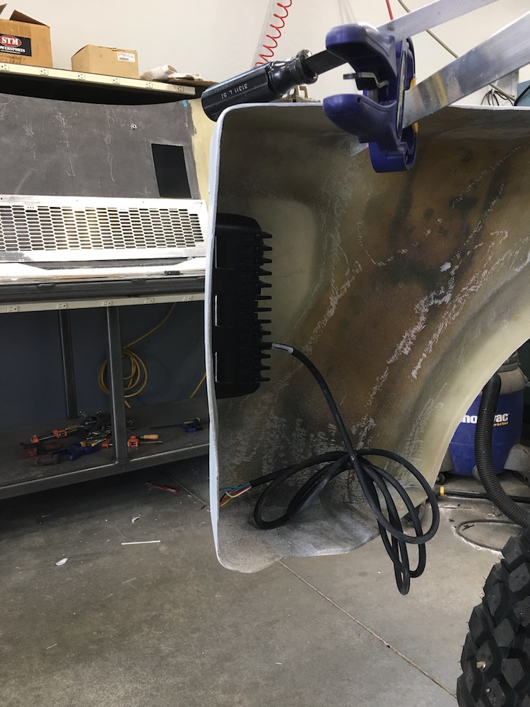
The lights will get covered with a smoked lens and I think there may be a side marker light or two in the vast open space on the side, in front of the light.
Working on rear bumper locating presently. Should have the majority of the rear clip done by this evening.
Dec 13, 2018
Got the grill 90 % installed (still have a couple bottom lip bolts to JB Weld in place) then had to put the light bar on the lip of the front clip to see what it's going to look like. The Rigid Industries bar has blue back lighting - looks pretty darned cool.
Started working on the rear sub frame/clip too. Getting the rear bodywork all parallel, spaced correctly from the wheels, located, etc. has been a bitch. Breath wrong and everything moves. you can see the pieces of wire strung across criss cross about the back to keep things from moving.
Bumper's a bit higher than I want - not sure if I'll redo the two bars coming off the rear bulkhead or if I'll just put a couple of bends at the top of them that drops it down a couple of inches and brings it out a tad. The back of the bed sides need to come up about an inch also.
The ends of the bumper will get cut off too - they don't need to wrap around the 6" or so that you see in the picture. I'll probably take about 3" off the length. I need to add another degree to degree and a half of bend also - the tips don't quite parallel the bed sides yet.
I'm still trying to figure out exactly how I'll be mounting the back end of the bodywork. The two holes in the top, where the supports are screwed to the glass, will get opened up and I'll be using Quik-Latches again (same thing that holds the hood clip in place) for securing the back of the bed sides.
Been looking at some of the other Mini-Raptor builds and some of the TT rear clips and still am not sure if I'll run a bumper across the back or if I just tuck a cross bar inside the lower lip. It'll make attaching the panels easier if I don't do a wrap around bumper as I need about 3/8" of clearance to get the Quik-Latches in place before they clip onto the mount.
Dec 17, 2018
Bumper tube tucked into bodywork - looks cleaner, better.

Still have a pair of Quik-Latches to install to hold the bottom corners of the bed sides in place. They're on a bit of an angled section so I'm still trying to figure out just where they end up - may not be visible when I'm done, we'll see...
I do like the way they hold stuff in place - extremely solid mounting:

Spare tire got tossed up into the back to get an idea of where it'll live.
The rear subframe will give me a lot of room for a nice, large QUIET muffler just behind the rear bulkhead. I'll be affixing the power plant to the frame rails next (it's presently just sitting in place) and then start working on the exhaust system.
Still waiting on the plumbing elbows and connectors to clear customs - what a clusterf*&k... I can't do anything forward of the engine w/o them either.
Dec 22, 2018
Tire mount complete. Now I have to figure out how I'll secure the wheel to the mount. More billet...
TOOOOOBING!!!!!

Ordered this on August 7th. I was at the point in the build that I had to get my plumbing done before I could move onward. I was told it would be a six week time period between order and receive. That's cool - we had a vacation and some other stuff so a six week break wasn't an issue.
I get a phone call around the end of October saying that I owe UPS something like 1100 bucks for a package from England. Huh? No, not right. The pieces only cost $270.
The fight begins...
Somewhere in the line of ordering the cost of the parts was put in at $27,000 instead of $270.00. I'm getting an import fee on $27K, not $270.
UPS asks for receipts, paperwork, etc..
I supply.
Middle of November, nothing.
I call UPS and get the run around and am given a phone number and name. Many calls later I talk to said person and am told "It's in the cue, we'll get to it."
End of November I send an email - same response, 'in the cue'.
Middle of December, not happy.... Start making phone calls and sending e-mails.
FINALLY get someone that has a clue who sends me to someone else that's supposed to have one too.
The number of recipients on the "TO" header for the email is now up to seven people.
"Can you send us hard copies of the order and proof of payment?"
Response from me:
Really? You're asking for that now? In this world of electronic retail you want a paper trail?
No, I don't have any hard paperwork.
I've provided everything I have.
The order was placed online (I've provided the copy I have of it). I live in Scottsdale and the items are from somewhere in England. I didn't stroll in and choose my items and get a receipt.
The payment was made via PayPal, online (I've provided a copy of the transaction) and I don't have a clue where to find a paper version of something that's always online with conformation email. Being that I've never received my product due to this silly customs issue I don't have ANYTHING physical in my possession.
We're talking about 8 dollars worth of import duty and this has gotten way out of hand, taken way too long and I'm sorry but this has put me right at the limit of my frustration level. Why must you make this so complicated?
Please call me if you think it will help so we can get this all taken care of.
Thanks
Five minutes later I get an email saying "Fill this out, scan send back" so I did.
Guess what arrived today???
WOO HOO!!!! I got my plumbing, I got my plumbing!
I wasn't charged the 8 bucks import duty either. BONUS!!
Now I just have to heal up from yesterday's surprise appendectomy. How's that for a birthday present (well... two days early). Can't lift anything over 15 lbs for the next 6, ahem, 4 weeks. Shit.
Still, I GOT TOOOOBING!!!!! This has been the stopper since August.
Dec 23, 2018 It's me birthday!
kustomfab2003
Glad to see you got your tubing, bummer on the appendectomy. Just curious, why did you have to order overseas? CBR and others have access to those same hoses don't they, or was it a initial cost thing?
Me
I tend to get blindly focused on items at times.
I already had a couple of feet of the stuff (no clue from where - it's been riding around in astorage box for years) so when I used some of it in the MR I figured I'd just stick with the same brand because, well, it's bad ass toooobing and I like the color.
Got on the Internet, discovered I could only find the pieces I wanted in England, where it's made (they're good making silicon, not so much with electronics) and pricing was actually very reasonable.
Placed an order and the fiasco began.
kustomfab2003
Got it. Because they were local to me and I helped set up their weld shop, I had always used CBR for my hose needs. But I can also understand wanting to stay the same as what you had already. When I was building my rail as well as my hybrid, they were always good about getting me the silicone hoses I wanted in the colors/sizes needed.
Me
Looking back I should have gone with CBR right off the start. Would have had my parts in a couple of weeks, if not days instead of months. Oh well.
Good god this getting old shit is getting old (54 today) - I'm realizing I get more and more stubborn about something silly like silicon hose being the same as something I had.
If I'd sat back and said to myself “just get another 2' long piece from CBR and put that one back in the box ‘o hose shit” I'd probably be done wiring the thing by now. But noooooo! I like THIS one, everything's gotta match IT...
Yeah and bite ya in the ass. Lol.
kustomfab2003
Hahaha... Been there done that!! Only 45 but the OCD and stubbornness still runs strong.
Dec 24, 2018
jimmy
Never a dull day at Yellow Dog.
Me
Nope, generally not. I'm, glad too. That same shit different day gets old quick. I'd be bored.
This morning I had to go get my paws grubby. Asked my wife to help me pull the hood so I had access to the radiator. She obliged with a grin.
Took me about 20 minutes to install all but two elbows, a reducer and two tubes. I need to shorten the long tubes that run thru the cabin and replace the OEM Yamaha pieces on the engine but my sore belly said "No, you're not doing that right now, go find the couch." so I'm sitting here at the computer instead - think I hear the guitar calling. There's a good couch activity.

As soon as I get the rest of the connectors in place and tubes to length I'll be able to mount all the plumbing and start working on the center tunnel that all this crap runs through.
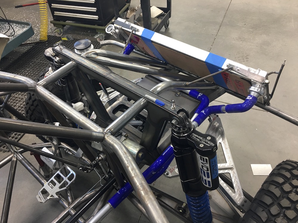
One of the biggest issues I've found with all the SxS that I've been in is with the radiator up front and the plumbing heading through the cabin, the heat starts to become an issue. The MR is going to be a fairly closed cabin (relative to an SxS) so I need to be very aware of air flow around and through it and heat control.
The radiator will end up having outlet ductwork that points the hot air down and out in front of the front wheels and out through the two vents on the top of the hood. The tunnel will get insulated with foil and I may even ceramic coat the panels that face the stuff inside.
Dec 27, 2018
Everything's mounted in place. Took four hours. One for each month of wait. DOH!
Had to make a reducer for one junction; the return line from the rad to the engine goes from 32mm to 28 so I made a set of smooth rollers for my knurling tool, chucked up a piece of the tubing I'm using for the cooling system and started making passes that were .5mm smaller each time. I'm actually quite impressed with how well the technique worked and how well the piece came out.
Here's the front section, all the tubing tucked in away from anything, mounted where it's safe and secure.
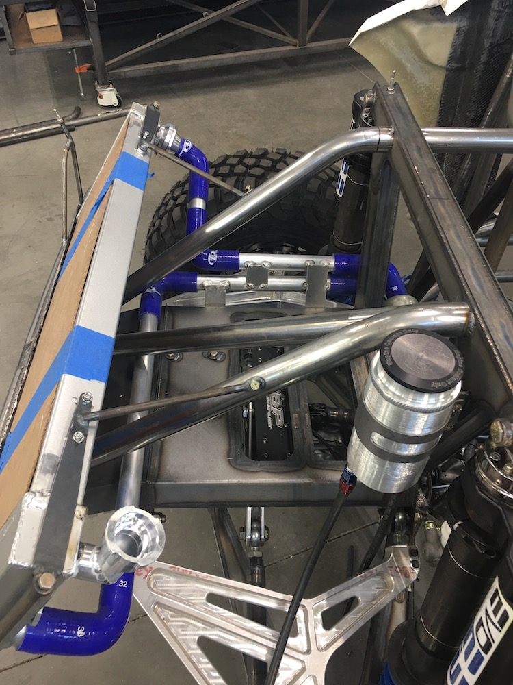
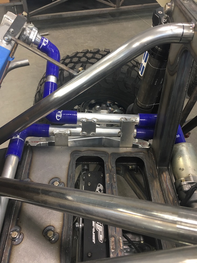

I was able to secure the two main tubes that run from front to back so they'll not argue with the drive shaft and/or anything else that happens to get stuffed into the tunnel that'll run down the middle of the cabin.
Now that I know where the coolant lines live it's time to tackle getting the fuel system plumbed and installed.
It's mill time. No, not Miller time, mill time. Gonna make some billet mounts for the pump.
Not sure how I'm gonna get the fuel tank out (not allowed or wanting to pick anything up over 15 lbs yet). I'll have to hit up my better half and see if she's willing to go pinch a couple of fingers pulling stuff outta the way with me.
This concludes the building that happened up through the end of 2018. Click on the link below to be taken to what happens in 2019.