
Home of K-fab
|
|
|
|
 Part IV - Let The Machining Begin
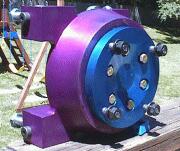
Making the hubs is a multi step process. First, I'll turn them down on the lathe to the basic dimensions. After I get the parts that attach to them, such as the rotors and bearings for the front hubs or the CVs for the rear hubs, I'll get the majority of the final dimensions machined. Next, I'll get the hubs close to final stage - that is not cut the bearing areas to tolerance, drill holes to full diameter or tap out the holes for the mounting lugs, I'll get them heat treated up to T6 values and then have them anodized. After the anodizing I'll go back and do the final machining processes. I can't have the bolts and bearings riding against the anodizing, so I'll remove it anywhere a bearing or bolt touches the hubs. I'm going to anodize the spindles and carriers purple and the hubs blue. All other small parts will end up green - I think.
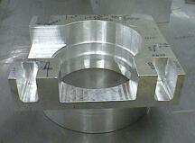
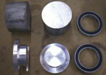 I received the round stock to make my hubs today (4/24/99). Four pieces of six inch diameter, four inch long 6061 aluminum. You can see that I ended up machining away about one half of the material to get 90% complete hubs for the rear. I still have to machine in the mounting lug holes, the CV mounting holes and the axle clearance pocket, but that shouldn't take too much time. I need the CV joints before I can do the rest of the work, as the hubs may end up being narrower than they are now. It all depends on the thickness of the CV. No matter how carefully I've taken measurements, there will always be variances that I'll have to deal with until I have the "parts in hand". Heck, it just makes it that much more fun.
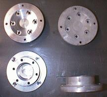
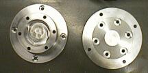 After getting the CVs, I was able to get the final machining done to the rear hubs. I had to drill the holes for the mounting bolts, counter sink pockets for the bolt heads, cut a pocket for rear axle clearance and also get the final hub thickness figured out. In the end, I was able to remove .500 of an inch off the thickness of the hub. They are ready for heat treating to take them up to T6 hardness and then they'll go off to get anodized.
 I'll start working on the front hubs as soon as I get my disk rotors. I finally decided on a 1999 YZ80 motocross bike's rear disk. It's 185mm in diameter and has a cut pattern that does not make it unidirectional. I need the rotors so I can get the mounting ring diameter on the hub the correct size. First I'll do the outside diameter work, cut the bearing holes and then finish the final shape between the wheel mounting side and the rotor side of the hub.
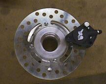 I cut the basic shape out of my pieces of billet. Getting the bearing holes cut in and getting the basic width cut down was the first step. About the same time I finished the first cuts, I received my rotors and my brake calipers. I purchased a set of Brembo F-04 calipers for the front brakes. These are very small, but powerful units that are quite often used on the rear of road racing motorcycles. I am familiar with the little Brembo because it's what I have on the rear of my Suzuki RG500 Gamma.
I have run into one snag with the front hubs. I have a clearance problem between the brake caliper and the bolts that hold the inner disk of the wheel in place. I'm looking into having new wheel centers done that have one half inch less offset. This will give me the clearance I need. If I can't get new centers made, I'll have to cut new front hubs that are one half inch wider. What a pain!
The final machining work, before sending them to heat treat and anodizing, was to get the disk mounting areas done and to get the finishing diameters and cuts done. The front hubs, like the rear hubs, are now ready for heat treating and anodizing. I'll do the final bearing areas, bolt holes and tapping when they all get back.
I purchased another piece of billet 6061 (18" x 6" diameter) so I could make another set of front hubs. After a lot of thought, I decided that I could make new front hubs instead of getting the new centers for the rims. I already have a couple changes I want to make to the front hubs anyhow. Being that the billet is not heat treated at all, it doesn't machine very well. I cut it up into pieces that are close to the hub sizes and then took it (and the rear hubs I made earlier) to heat treating. I have enough to make a spare set of rear hubs too.
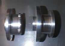
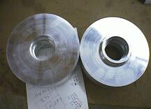
 The picture to the left shows the old hubs and the new hubs. See how much larger the new hubs (right side) are? I had to make them .600" wider so I would have enough clearance for the brake caliper. To make up for any loss in strength from moving the hub outward, I also moved the bearing out and made the area wider too.
I went ahead and cut a new set of rear hubs also. Notice the difference between the first set and the new pair? The discoloration is from going through heat treating. The hubs on the left are the new pair that I cut from the heat treated billet.
return to machining's table of contents
 I started working on the rear carriers last night (4-28-99) - boy this is going to take a while. Ever try to punch a five inch diameter hole in a four inch thick piece of aluminum?
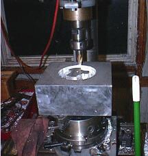
My first step was to use a four inch diameter bi-metal hole saw and cut down about an inch into the block, right in the middle of it. Then I machined three pockets down into the block inside the hole I cut with the saw that the jaws of the three jaw chuck would fit into. I turned the block over, set it on the chuck (which is on a rotary table) and began the long and tedious process of cutting down into the block. After about two hours of work, I had removed a ring that is five inches in diameter, two inches deep. I turned the block over and started the same process on the other side. I'm down about an inch and still have an inch to go. I figure I'll have the bearing hole roughed in with another hour's work or so. 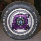 I'm guessing it's going to take me about four hours to get all the way through the block. After cutting the bearing hole, I'll still have to go in and machine out the link mounting lugs and do the main body shape too. I guess that by the time I've finished one carrier I'll have twelve to fifteen hours of work done. I HAVE to get a real milling machine!!! Yes, I'm in over my head, (uhm, neck deep is more like it) but I wouldn't have it any other way!
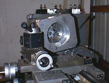
At first I was worried about working with a chunk of aluminum that is four inches thick, nine inches long and eight inches wide spinning away at 1,240 rpm, (it actually makes a whirring sound as it spins on the lathe, and just barely clears the lathe bed) but after a few passes with the boring bar I was quite a bit more comfortable working with it. I have the basic hole cut through the piece now. I'll finish the bearing areas and then get the rough cuts for the heim mounting lugs cut in soon. Then I'll work on getting the final shape of the carrier cut out. Once again, as with all my aluminum parts, I won't cut in the final bearing surfaces or bolt holes until after they come back from being anodized.
 (5-8-99) Chips, chips everywhere. The blocks of 7075 aluminum (8" x 9" x 4") for the carriers that I started with each weigh thirty pounds. I'm now about eighty percent done and down to just over eleven pounds on the left carrier. I figure that by the time I'm done, the carriers will weigh about eight to nine pounds. I turned down the area around the bearing housing section and what an amazing amount of aluminum chips and "worms" I encountered. I had to set up a small piece of clear plexiglass (to look through) and a large piece of cardboard to shield myself from the shower! I have little burn marks all over my arms from the flying metal. The pockets for the heim joints (mounting lugs) have been cut in, the holes for the drag link mounting points have been drilled and I've removed a lot of material that was between the pockets. I still have a one side to cut down and then I'll blend the mounting lugs into the body around the bearing housing.
 I did make one possible mistake in the order of my machining steps. I think I should have turned down the area around the bearing housing section of the carrier before I started cutting out the mounting lugs. The block of aluminum was fairly well balanced when spinning on the lathe before I did any of the pocket work. After I cut out a couple of the pockets, I noticed that the lathe vibrated a bit. Now that I've removed half of the material on the mounting lug side of the carrier, I'm sure the piece will be way out of balance. I still have to go back and remove some more material with the lathe, so I'm not sure how I'm going to go about it yet. I figure that I'll get as much of the aluminum around the mounting lugs removed first since the less there is spinning around, the less out of balance it will be.
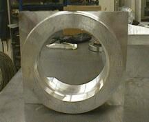
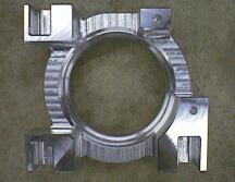 I've finished the left carrier! (Well, other than the final after anodizing cuts.) I ended up with a weight of seven and a half pounds and three trash cans worth of metal shavings and chips. I figure that I've put in approximately fifteen to sixteen hours of work on it. I'll keep track of the time it takes to do the right side carrier. I was really worried about turning down the bearing housing section of the carrier on the lathe, but it ended up being no problem at all. All the weight I removed on the mill around the mounting lugs ended up being my saving grace in keeping the balance of the piece while on the lathe and doing the final taper was a breeze. Looks pretty good, eh?
I started on the right side carrier two nights ago (5-10-99). Three and a half hours later, I had a hole through my block of billet. I used a slightly different process for removing the middle than on the last carrier. I drilled holes all the way through the block and then milled down over the holes. It gave the chips a place to go and also put less of a bind on the milling bit as I made my passes. I also got the hole cut to the required five and one half inch inner diameter. The basics are done and the next step is to rough in the shape of the carrier. More chips, more burns! Gee, just can't wait.
I'M DONE WITH THEM!!!
 The rear carriers are FINISHED! After about thirty hours of machining I'm done with them. This has been the hardest machining project I've ever attempted and feel like I've done a great job. To take a couple of large blocks of aluminum and actually make a mirror imaged pair of these carriers with my limited equipment and ability is pretty self satisfying. I was able to hold about a .010" difference between the two pieces which is just fine for my car.
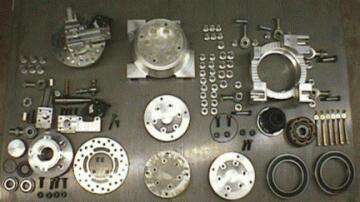
I also cut out the spacers for the heim joints. I had three different sizes of spacers to make and I made spares too.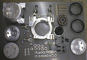
As soon as I make the spindles (my next step) I'll be done machining out the major parts.
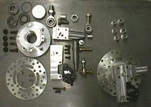
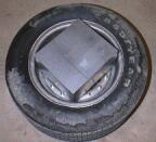
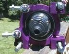
 I finished bolting up all the parts that make the rear carriers. Three different sized and shaped spacers, two different sized heim joints, a CV joint, a pair of bearings, a hub, CV joint cover and a hand full of bolts are all that's required. (as if that's not enough!) They fit into the rear rims perfectly with enough clearance that I don't have to worry about the rim being flexed into the carrier. All I need now are axles for the rear end and I'm done with the parts I need. I can't wait to get the frame to the point that I'm ready to attach the rear carriers!
return to machining's table of contents
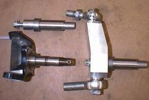
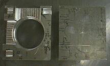
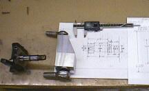 To see if I was going to be able to work with larger pieces of aluminum, I decided to make a prototype front spindle. I had a fairly large chunk of material to work with so I started milling away and after a few of hours, I ended up with a spindle that looked like the drawings I had done. I soon realized that the spindle I had designed was HUGE!!! I started taking off more material until I had a spindle that was the right size. After another couple of hours of hacking away, measuring and machining and I finally had the front spindle done to my satisfaction. I had to cut away around the mounting points of the heim joints so that they would clear through the travel and steering range and I also cut the thickness down quite a bit more too. So far, I've ended up with a spindle that weighs less than the stock Pilot spindle and has higher strength. You can see the difference in the machining between the two pictures.
Next I turned down an axle stub to the dimensions that I had and when I was done, I actually had two pieces that fit together and looked like the drawings that I had made. It looked like I was going to be able to make the parts as I needed. All I have to do now is wait until my material arrives.
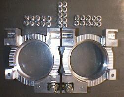
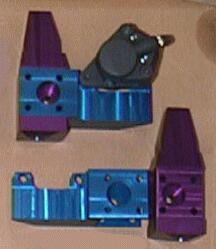
The New Spindle Design
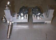
As you can see, I've done the basic work on the new spindles. They are two interlocking pieces. If you will look closely at the spindle assembly on the left side of the picture, you can see how the control arm/caliper mount slides onto the main spindle body.
Getting the calipers mounted in the correct position was tough. I machined the control arms and bodies in pairs so they were exactly alike. 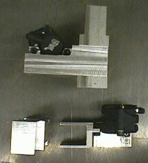 It paid off too, as the arms slip onto the bodies perfectly. They are tight enough that they don't have any play, but they slide on very easily. I'm getting better and better with the mill each time I use it. (I still wish I had a real milling machine!)
 I still have to cut out the axle mounting holes, drill a few bolt holes and do the final shaping of the bodies and control arms before they are done, but that shouldn't take too long. For once, every thing is going along smoothly and I've not run into any major problems (yet). I should have them done by Monday so hopefully, I'll be anodizing next week and starting the chassis.
The front spindles are FINISHED!!! I'm now done with the major machined aluminum parts. I had a bit of a clearance problem with the brake calipers and rotors but a quick trip to the lathe took care of that. I still have to cut pockets in the steering arms for the heim joints that the tie rods attach to and I need to make another set of axle stubs, but that should be pretty easy and quick. I have to tack down a piece of 1-1/4" 4130 chromoly to make the axles from too. Once again, I'm really pleased with the way my front end parts have come together. Making a hub, axle, bearings, caliper, disk rotor, spindle body and control arm all fit together as well as I have was a real challenge. Even my wife thinks it looks good!
return to machining's table of contents
return to table of contents (car building home page)