
Home of K-fab
|
|
|
|
 During my travels of roughly seventeen thousand driving miles this past racing season, I've had a LOT of time to think, ponder and design. I can visualize the majority of the final car and with the help of AutoCad, I've designed and drawn the parts as I see fit.
My starting point of my car is the overall width and wheel base allowed by the racing sanctioning bodies. Sixty-eight inches is the maximum width allowed and the wheel base can be anywhere from sixty-four to seventy-two inches in length. I've chosen to go with a basically square footprint of sixty-seven inches in width and a sixty-eight inch long wheel base. I'll be able to change the width of the car by about one inch either wider or narrower and the wheel base can be changed by approximately four inches, giving me a range of sixty-six to seventy inches long.
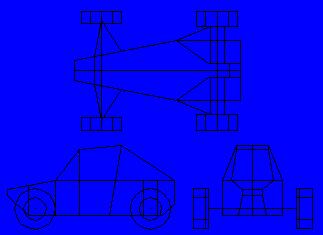
 As I begin my work with AutoCad, the chassis begins to take shape. All this work is preliminary and does not mean that it's the end product. The chassis is drawn as a stick figure designating the center lines of the tubing. No bends or bracing are shown either. This is just the beginning so I can get a feel for the locations of components and their mounting points, lengths of suspension pieces and an overall idea of what the car might look like. This is what makes AutoCad such a helpful building too. I can move, change, locate and modify anything I want with just a few keystrokes instead of cutting, grinding and rewelding an actual part on the car. I can calculate angle changes, camber and caster changes, and take measurements at any point through the suspension travel too.
Getting the basics of the front suspension's design down was not a problem. I knew that I wanted to have thirteen inches of travel, a-arms as long a physically possible and the chassis as narrow as possible where the a-arms attach. The challenge came in locating the actual suspension mounting points in a three dimensional drawing space. The shape and size of the a-arms would come from these location points. I was going to put Acad to the acid test (well, at least for my fairly limited Acad abilities). In order to get the true chassis design figured out, I was going to have to take three separates sets of drawings, blend them all together and then pull out a three dimensional model.
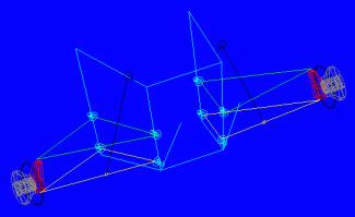 By starting with a view of the front of the car, I was able to place the front hubs and spindles in the proper location to give me a sixty seven inch overall width. Since the spindles have the mounting points for the suspension, I now had my first set of a-arm mounting points located in 3-D space. I already had a rough 3-D drawing of the car, so I was able to locate the front suspension and hubs in the proper spot on the chassis and then came the hard stuff. The way the suspension attaches to the chassis had me drawing in so many angles and location points that I about lost my mind. (anyone that's messed with Cad programs understands "construction planes". I had seven different construction planes intersecting each other!) The lower a-arms took shape, the upper a-arms were figured out and then I had to locate the shocks. More drawing planes, a lot of different arcs and circles and I finally had a shock mounting location that gives me the desired 1.75:1 motion ratio. The motion ratio is the ratio between the amount of travel of the suspension and the shock shaft travel. My front end's suspension design was complete.
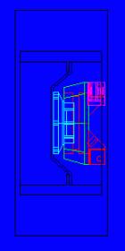
"Installing" the rear end of the car onto the 3-D drawing I now had was no where near as hard. The angles I was working with now were all square to each other. Just insert the drawing and move it to the needed location. The only part that posed any problem was locating the drag link and shock mounting points on the chassis.
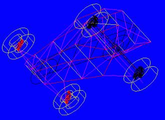
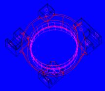 The rear carriers of the car have posed one of the biggest design problems for me. I have to attach five links and possibly the shock to it. Getting all these links onto an eight inch by nine inch block of aluminum has been a challenge. More than likely, I'll end up attaching the shock to a beefed up lower link that will come off the frame and be shaped very similar (gull wing style) to the front a-arm's leading leg. The rear carriers will have inboard bearings and CV's, meaning that the CV actually rides inside the bearing and the pivot point of the axle is inside the carrier. Also, this design eliminates any sort of stub axle. The CV will actually attach to the drive hub of the rear wheel (the blue part in the picture). By utilizing this type of design I can make the carriers fairly narrow, I have less parts to make/break and it will allow me to get most of the heim joints as close to the inner edge of the rim as possible, allowing for longer suspension arms. Machining these carriers is going to be a challenge, too. Getting the basic shape cut out will probably take fourteen to fifteen hours and then at least a couple more getting the final cuts in. And that's just one carrier! I'll have to duplicate it too!
The rest of the chassis, the engine location, seat and control's positions will all be placed as I build the chassis. The car will chassis will be built on a jig and as I position the other components, I'll jig up the locations of those mounting points too. When I'm all done, I will have all the cut angles, mounting positions, tube lengths and bends recorded so I'll be able to replicate the finished chassis. I'll also be able to use the jig to check that my chassis remains straight during my racing.
return to table of contents (car building home page)
Return Home