
Home of K-fab
|
|
|
|
The Gecko came to Ohio with some major problems and needed changes. I'll start at the back of the car and work to the front. As I start working on that section of the car, I'll make the list a link to follow along.
Steering - A VW Buss steering box? No Way! How about a nice Rack and Pinion? (12/04/00)
The Roll Cage - It needs bracing, BIG TIME! (2/15/01)
Frame - The lower rails must be moved up, including the engine bay. (10/29/00)
Drive Train - Engine and Tranny. (10/29/00)
Rear Suspension - New rear carriers and Suspension stuff.
 One of the big worries with the Gecko was how we were going to start it. Believe it or not, most snowmobiles don't have electric starters - even big bore triples. To start one, you reach down in front of your right knee grab hold of the handle and give it a quick yank. This just would not work for the car. Heck, we would have to run pulleys, extra cord and all sorts of monkey rigging to even get the pull start where we could reach it, much less be able to pull it!
  Fortunately (for us!), Arctic Cat offers a bolt on electric starter system for the Thunder Cat 900 (our engine). The kit includes everything from the starter to full wire loom complete with key start and battery. It truly is a bolt on system (very rare that "bolt on" really is!) that just required the replacement of one motor mount with the starter's mount and installation of a ring gear on the clutch.
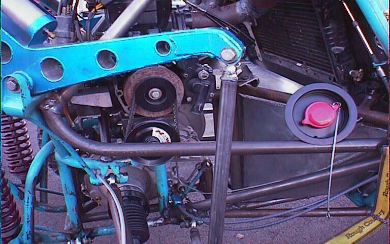
After getting the main components (starter, gear) installed on the motor, I decided to see what was going to be involved in mounting the power steering pump to the motor. I had the perfect spot for the drive pulley - just remove the pull starter mechanism and there sits the flywheel. A quick check and sure enough, with a little machining, a slightly longer bolt and a bit of case work and the drive pulley for the power steering bolted right on. I still have to make the bracket that will hold the power steering pump, but that shouldn't be too terribly hard to do. I need to get a belt first so I have a better idea how far out the pump is going to have to be mounted. Who knows, it may end up getting mounted below the motor, but I'm afraid it would be in danger of flying debris in that location.

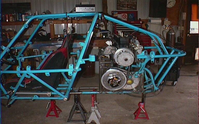
 The starting point of the car was to get the chassis set up like we want. As I've mentioned before, the guy that built the Gecko is something like 6'8" and over 400 lbs. To accommodate him, he dropped the chassis about three inches from just in front of the seat all the way back to the rear of the car. My original plan was to cut the lowered section out and raise it up so that it was level with the rest of the lower frame rails. This would mean that I would have to cut the rear suspension area out and shorten it up by three inches. Thing is, this would interfere with the way the shocks and cantilever parts mounted. The shocks were already to the point of just starting to bind against the cantilever arm and by raising the lower part, this would have compressed the shocks three inches, loosing travel. Instead, it made sense to just cut the entire rear end of the car off and then redo the upper rail where it mounted to the rest of the chassis. This way I wouldn't have to try to redesign the shocks and cantilever
  arms mounting points. It also made getting the transmission and engine mounting easier. I wouldn't have to climb in and out of the chassis while trying to fit everything in. (If you look closely in the picture on the left, you can see that I'd already cut the seat rails out. See how the rear frame rails mount below the main chassis line?)
I cut out the seat rails and then cut loose the back half of the chassis. Next I mounted the seat rails up in the chassis and was amazed at the difference in seating position! I was actually able to see out of the car, the wheel seemed to be much closer to the right position (although it's still tilted forward too much).
 The first step with the Gecko's drive train was to get the transmission mounted. The original setup that came on the car was nothing more than a large sprocket mounted to a spider gear that had bearing carriers and then CV flanges. This all sat in the middle of four down tubes that acted as suspension mounts and sprocket mounts. The Hymark tranny (only the world's biggest piece of shit) wouldn't fit in where the sprocket setup was. One of the down tubes would have to be cut out.
With the front left tube gone, the tranny fit in just about perfectly. I fabricated mounting plates, added a couple pieced of tubing and had the tranny mount done. I'll still have to redo the tube that was cut away, but until I get the motor mounts in, I'm not sure how and where braces will be placed yet.
One concern has been the alignment of the clutches. The Thunder Cat engine is pretty wide and I've never been sure of how well the motor would be centered in the frame. Sitting on a bench, it doesn't look like the tranny's clutch offset is nearly enough. But, by the time I got the tranny mounted, the drive clutch on and a test measurement of the engine, it appears that everything's going to line up really well.
 The next step was to hang the engine off the ceiling and move the rear end of the car into place. At first I was trying to keep the engine low and out in front of the tranny, but that put the exhaust pipes through the back of the seat - that wouldn't work! So, I started moving the engine upwards. By the time I had it more or less located, I needed to cut off more of the rear cradle. It looks like I'll end up integrating the motor mounts and the suspension's upper bracing all into one neat package. I'll also have to figure out how to get around the clutch. Naturally, it sits perfectly aligned with the frame rail. Some nice things about having the engine sitting right on top is that it's easy to get to, the carbs are easy to work on, the pipes will have a lot of clearance and there will be room for a fairly large fuel cell under the pipes.
After getting the majority of the original engine mounts cut out of the back half of the car and getting the transmission mounted, it was time to insert the engine.
Being that this is a torque converter set up, there are three really tricky things to getting the engine in correctly: 1) Correct distance between the centers of the clutches (happens to be 12.176") and 2) Getting the correct offset between the two clutches so that when the drive clutch closes down on the belt, the driven opens and the belt stays in the correct plane between the two. The offset of the engine we have is 1.367" and 3) Making sure that the axial lines of the engine and the transmission are parallel (they should be parallel along the engine's crankshaft and tranny's input shaft) . I set out by making a couple of jigs. The first one is the center to center jig. It's pretty straight forward. A piece of tubing with a washer on one end that's been turned down a touch so that it slips into the drive clutch and then can be bolted into place and the second is just two pieces of strap steel that have been welded together with the correct "step" (the offset distance). This one gets placed into the drive clutch and then the offset side is supposed to come up flat against the back of the driven clutch. With these two tools in hand, I was ready to tackle the task of inserting the motor into the rear half of the chassis.
I figured that the easiest way of getting the engine in position was to hang it from the rafters of the shop and lower it into position above the tranny. I carefully leveled out the engine and then began to lower it into position using the center to center jig to get the correct distance and then I put the offset jig into the clutch and got the engine located side to side. After finding this place in space, I started cutting and bending tubes to match the locations and tacked the engine into place. Right off the bat, I screwed up and somewhere along the line, I managed to get the alignment of the engine and tranny off. First time to cut the engine loose from the recently made mounts...
After getting them aligned again, I made an attempt to get them held in the correct position and tacked the engine cradle in again. Seemed like it went in really well. Then, I stepped back and realized that the rear frame section had "fallen" over to one side a touch. It was enough that the flywheel end of the engine was about a quarter inch lower than the driven pulley side. Once again, out came the cut off wheel and the engine cradle was loose again.
Third time's a charm, right? WRONG!!! (well, sort of). This time I made sure that the two shafts were parallel, the center to center distance was correct and the side to side spacing was good. Everything looked perfect. I started tack welding and checking alignment with each tack. So far, so good. Nothing moved and I went around all the mounts and welded them up. Next I pulled the engine off the cradle and then went in and welded everything up, added a bunch of braces and pretty much had the engine mounting done. I was going to have to add a couple more braces, but I couldn't do them until I got the rear of the frame reattached to the front half of the car - which was to be the next step...
I placed the rear frame, with the engine and transmission mounted, on a couple of jack stands, set up another jack stand for the front half of the chassis and then wheeled the front half over to see how everything was going to line up. The two chassis pieces came together quite well - even with raising the back piece up three inches compared to when I cut it off. Then I noticed something. It seemed like the engine was a bit farther forward than I had expected. I still have to mount three expansion chambers and a quick test fit showed that they were going to almost hit the rear of the seat! This isn't too much of a problem, as I'll have to cut them up a bit and custom fit them into the frame, but what was a problem was that they came right into the area that the radiator sits in. NOT GOOD!!! I mounted the radiator to confirm my fears and sure enough, they came right thru the bottom of the radiator. I was going to have to find at least six inches somewhere!
After two days worth of work building the engine cradle, I was standing there looking at the engine, the radiator and the area where the expansion chambers go thinking "This can't be happening". This arrangement wasn't going to work! My first thought was to see how far back I'd have to move the engine to make it all work - looks like about six inches. Where was I supposed to get six inches (easily)? I looked into lengthening the chassis right where the two pieced come together and it seemed like the right place, but still, it made for messy work trying to get the expansion chambers to clear the bottom of the radiator. More thinking - I knew what I had to do, but we're talking about TWO DAY'S worth of work...The engine cradle had to be cut out and the engine had to be moved back. In doing so, I'd gain about four inches of clearance between the engine and the radiator AND it would lower the engine too, so I'd gain vertical clearance too. Once again, out came the cut off wheel and the sawz all. All my freshly done work was cut out.
To gain the needed clearance, I'll have to do three things: 1) Move the radiator forward in its mounts. Right now, the air inlet to the radiator is built into the fire wall. It's set up so that the radiator is mounted to a flange that offsets it behind the fire wall about two inches. By cutting the lip down on the flange, I'll be able to move the radiator forward about AND by relocating the engine (damn) I'll gain another three to four inches. Should be just about enough. I may still have to add a couple inches in the frame area, but I'll see about that when I finish getting the engine BACK in for the fourth time!
 This time everything worked like a charm. I started out by making sure the transmission was level and with the jigs attached, I once again positioned the engine above the tranny from the rafters. As the engine was lowered into place, the jig let it rotate (around the axis of the transmission shaft) towards the rear of the frame. I was able to get the engine positioned so that the carbs were about one half inch from the brace that runs between the cantilever mounts, gaining about four inches of room up in front. And, as a bonus, the engine ended up being about two inches lower than the previous attempt. This worked great for two reasons; first, it lowers the center of gravity a touch and second (and more importantly) it allowed me to make all the mounting brackets and tubes shorter so they are stiffer and stronger. I also learned from my previous mistakes and was able to make the mounting cradle much stronger with fewer pieces. All in all, having to redo the installation over was really a good thing.
 After getting the basic engine mount made, it was time for a test run to see how the two frame pieces were going to fit. I took two pieces of one inch tube, inserted them in the lower frame rails of the back half of the chassis and then stuck them into the lower frame rails of the front half of the car. They lined up just about perfectly (Thank You!). I made sure that they were about a foot long so I would be able to slide the two chassis pieces back and forth so I would be able to get the correct spacing for the expansion chambers clearance from the radiator.
Next step was to fit in the radiator. As mentioned before, the radiator fits up against a flange on the fire wall. This flange was about two inches deep. I cut it down to one half inch. Bolted the fire wall in, fitted the radiator up against the fire wall and strapped it in place with tie downs. A quick hammer mod to one corner and removal of the filler neck (it will get relocated) and the radiator fit perfectly. A little jockeying of the two chassis pieces and the final decision of stretching the chassis five inches was made. I cut the spacers, made sure the two pieces were aligned and welded them together. It was back to being one chassis. New upper rear down tubes (the ones that come off the roll cage and go to the back upper frame loop) were made - this time they're high enough that they should protect the cantilevers a bit better in case of the dreaded roll over. This also made the chassis quit flexing while I was working on it. I had gone from having the expansion chambers come into the driver's compartment and about half an inch of clearance between the exhaust flanges and radiator to having close to eight inches of room to run the expansion chambers. It all worked perfectly.
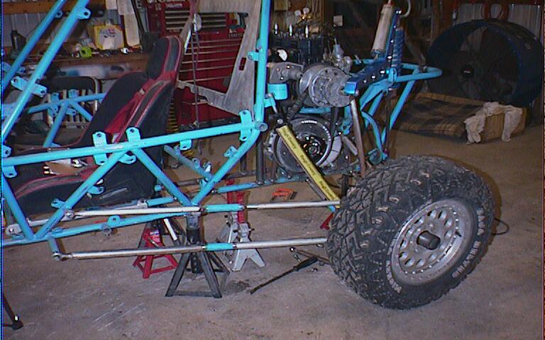
After getting the down tubes in, it was time to see how the suspension was going to fit up. Originally the rear end of the car was about 64 inches wide and the front end is 68. We wanted to have the rear end at least the same as the front, so I bolted up the rear suspension links and carrier on one side and started taking measurements.

 With my modifications to the rear carriers, the links were going to have to be at least four inches longer and since we wanted the car to be about four inches wider, the links had to be extended about six inches. Same for the drag links that come from the front of the chassis - they had to be lengthened by the same five inches that the chassis was. I cut up one set of links, extended them accordingly and test fit everything. In the end, I'll have to make new links all the way around, each out of a single piece of tubing instead of the cut and lengthened pieces. I'll probably end up making the links closer to eight inches longer over all because right now the heim joints are sticking out almost completely. Anyhow, a quick test of how things went together and the rear suspension looks like it's gonna work great.
 Last on the list for the night was getting the radiator mounted, not just hung in position. I had to modify the original brackets that hung the radiator. The upper mount was the one that took time. I had to cut off the tabs, figure out where the were going to have to be relocated and then put it all back together. It wasn't hard, it just took time. The lower mount was pretty much a breeze. Originally, it mounted to the upper frame rail on some tabs. Since this rail was no longer present, I tied in the upper frame rail from behind the roll cage to the front of the engine mounting frame on each side and then made new mounting tabs that held the bracket in position. Now I'll have room for some good cross bracing (that wasn't present) in the roll cage hoop. By this time it was 3:00 a.m. and I was done for the day.
My next step will be to work on fitting in the expansion chambers in and then finishing out the engine mount bracing and the frame bracing. The engine mount stuff won't be too hard, the frame rails - well...I have to go around the clutch on one side, making it so that removal of the clutch is easy and I have to do the same on the other side for the fly wheel. I'll also have to build in the mount for the power steering pump. It's going to get positioned below the engine.
 The Hymark tranny uses Ford (rats) Escort (double rats) transmission parts. So, the output shafts are, obviously, from a Ford Escort. I found the first output shaft at a local wrecking yard. Pretty much a "plug 'n play" scenario. I had the Hymark tranny with me, so I took it into the trailer where all the axles were and started seeing which one would plug in. Naturally, I was able to only find ONE! Twenty bucks later, a few greasy rags and I had one of my transmission stub axles. No big deal for now that I only had one, as I had to modify it quite a bit. (the one on the left is the modified one) First, the cup was cut off and then a steel ring was welded to the outside. After that, I machined the ring down to accept a 930 CV (go big so the car can come home!). After getting the first one set up, it was time to find output shaft number two. I pulled out the phone book (yellow pages) and started looking for the salvage yard section - and there it was - Axles, rebuilds, all makes, all models. "This sounds promising". I called the place and he said come on down. I took my stub with me, the man at the shop took one look at it, dug thru an old grocery cart and triumphantly pulled out a short axle. "This is what you need." he said. I pulled out the measuring tools, and sure enough, he was right. He took the axle apart, cleaned the cup up and handed it to me saying it was going to cost a whopping FIVE BUCKS!!! Talk about getting lucky! Not only that, but I was able to give him (get rid of) the rest of the axle that the other stub came from. Double points for me! (:
I'll get my new stub (boy that doesn't sound right) and the outer stub axles sent off to a buddy to get them modified for the 930 CV's. When it all comes back, I'll just have to plug in the stubs, bolt in the CV's and get the axle length figured out. Supposedly, I can order 930 axles from a couple different places that sell them in incremental lengths of 1/2". We'll see. Looks like the drive train is running along smoothly so far. Then again, I do remember all the hoops I had to jump through with the Moskito...

 One of the main things that has to be changed in the rear end of the car - besides raising the rear of the chassis three inches - is to redo the rear carriers so that they A) have more ground clearance and B) so that everything mounts inside the rim.
This helps in two aspects. First, it gets the links up out of the way of rocks and "bad things" in the desert and it will allow me to use longer links so that there is less angular change of the axles and of the CV's through suspension travel. The pictures on the left show the carrier as it came on the car and also shows how much the suspension that came on the car hangs out of the rear rim, just waiting to get torn off. The picture on the right shows the beginning of the new carrier - you can't see too well from this shot, but the mounting points are at least two inches inside the rear rim.

 I started out by taking the carriers that came with the car and stripping off all the suspension mounting hardware. This left me with just the bearing tube. I wanted to get the links up higher and mounted inside the rim, so I made the overall height of the carriers shorter and brought the mounting points in so that they are now just about even with the back side of the bearing tube. On the bottom of the carriers, I cut the bolt spuds out of the old carrier's horizontal mounting tubes, cut new lower link mounting tubes, welded the spuds in and redid the mounting of the lower tubes. For the top of the carriers, I pretty much just cut off the upper link mounts, shortened them, repositioned them so that they were straight above the lower link mounts and welded it all in place. Once again, by moving the mounting points, not only do I gain clearance and protection, but by moving them inward, the leverage stress put on the carriers has been drastically reduced. Originally, the suspension carriers pivoted about four inches out away (towards the car) from the bearing section of the carrier. And, with the wheel mount about four inches out the other way, the rear wheel acted like it was sitting on the end of an eight inch long lever where it attached to the suspension. This all equates to induced stress that just doesn't need to be there. I was able to shorten that lever down to about four inches - so I have about half the lever stress. Should make it all stronger.
The trickiest part of it all was figuring out how to mount the drag link/shock link section of the carrier AND get it to clear the 930 CV. After a bunch of tack welding, measuring and such, I finally figured out the correct location so that the drag links didn't hit the tire wall. A couple more braces and it all looks good to go. Now all I have to do is figure out how I'm going to mount the rear brakes and calipers. We decided to change the setup from inboard brakes (like the car came with) to outboard brakes - hidden inside the wheels. The reason for this is that if we loose an axle or CV, we still want to be able to use the brakes! If we kept them inboard, the brake would have no way to stop a tire that wasn't still attached to an axle. No brakes is a BAD thing. (trust me here, I lost them in the Moskito at Crandon and it wasn't fun!)
(10/29/00)One other problem with the carriers original design is that the lower links attached with a bolt that went through the heim joint and then threaded into the carrier. This type of mounting is called "single shear", meaning that there's only one point on the bolt that needs to break before the heim goes off it's own way. To fix this problem, I just added another strip of steel on the outside of the lower heims and brought it up just below the upper mount. This gave the entire carrier more bracing, better triangulation between the mounting points (more strength) and a place to hang the caliper on.
Brakes are the next step. The rotors that came with the car were off the same slug GPZ600 that the engine came from. These were originally mounted inboard off each inner CV. This wasn't going to work for us. We need the brakes outboard - that is in the rim. The rotors and calipers off the bike, and the rotor carrier, are not right for the setup we have. I called Wilwood Braking Systems and ordered a set of rotors, calipers and hats (rotor mounts). I'm hoping that they show up about the same time the inner and outer stubs get back. They were sent off to my buddy that has the ability to weld up flanges to accept the 930 CVs. Once I get everything, I'll be able to get the brakes mounted, get the wheels attached to the rear carriers and then get the rear suspension attached to the frame. The back end of the car's going to get widened and being that the new carriers have mounting points that are closer to the axle, I'll probably end up lengthening the links by at least eight inches. Once I get the carriers mounted up, then I'll be able to figure out the axle length and from what I understand, I should be able to call any of three or four off road places and purchase my axles without any problems. We'll see!
 After getting the rear rotors, hats and calipers, I had to redo part of the rear carriers again. I had to cut off the back half of the carrier's webbing to make room for the calipers to mount and then I had to make mounting tabs for to hold the calipers in the correct location. To start the project, I first worked on the rotors and hats.
 The plates (don't know the technical name - it's the part that slides over the axle and holds the wheel on to the entire assembly) that the wheels attach to had to be turned down about a quarter inch so that the rotor mounting hat would slide over the top of the plates - this gave me the correct offset for the disk rotors. If I went to the back side of the plate, the rotors hit the carriers. It also set the rotors in the correct spot inside the rims. After getting the rotor and hat assemblies set up, I had to install the calipers. The problem is that the calipers ended up hitting the inside of the rims. SO, off came the rotors
  and I cut a quarter of an inch off the diameter of the rotors. It was all the clearance I needed. I clamped the calipers to the rotors, figured out how/where I was going to mount the calipers to the carriers, and made the mounting plates. Bolt the whole thing together and don't you know, it actually worked! The calipers have about 1/8" clearance between them and the inside of the wheels and everything fits perfectly!
 The next step was to fit it all up to the chassis. I started out by using the original links - this put the wheel in really close to the car. Some use of a tape measure, and I was able to figure out how much the rear links were going to have to be lengthened. Turns out it's about six inches. I cut up one set of the links and extended them to the right length, and test fit again. The final overall width of the rear end worked out to be 70 inches. Right where we wanted it to be. I hooked up the rear suspension linkage, ran the suspension through it's travel and decided that everything fit just as it was supposed to. Then came the lathe and welding work...
The car originally had 1/2 x 1/2 heims everywhere. These are just not that strong. We decided that using 5/8" shank, 1/2" heims would increase the strength of the suspension components' mounting points drastically. Also, since the original heims were all right hand thread, adjusting the links was a pain in the butt. I cut the spuds out of the ends of all the links, drilled them out and then threaded them to accept the 5/8" shank of the new heims. Also, to make adjustment easier, half of the spuds were threaded with left hand threads. New links were cut, the spuds welded in and I had my suspension components done. I assembled the parts and everything fit together perfectly! The rear suspension was done!

 I dropped the rear of the frame down so that it's sitting 2" off the floor, put the shocks in full compression and then checked the links that go from the rear carriers to the cantilever arms to see if they were the correct length. Turns out they were perfect. I'll double up the links to 1-1/4" instead of the 1" single tube (like the lower drag links are). It worked out so that I have about 18" of travel and 20" of clearance at full droop and 2" of clearance at full compression. The front and works out pretty well already. It gives 3" of clearance at full compression. Install the limit straps and the rear end's done.
Quick lathe work on the inner stubs and I'm ready to figure out axle length. The guy that did the stub work for me sent me a 930 axle that has a tube welded to one end and then the other end slips inside and locks down with set screws. Will let me figure out the correct length. Then I'll just call German Auto or someone of the like, and order the axles.
I finally got the tranny shifting figured out - it has two buttons - one has three positions (H N L), the other has two (Forward, R). Now I have to figure out how to get the shift pattern figured out so that reverse is just "pull back" on the lever, low is forward position #1 and running gear is all the way forward. Naturally, the button sequence doesn't make this easy...we may end up with H N R L or N R L H or any screwy combination. Hell, it's something to tackle a bit later.
After seeing the rear suspension in place, I realized that I have all sorts of room to run the pipes right behind the seat/under the radiator and then send the stingers on out towards the back of the chassis. The power steering pump is gonna get put under the engine. Looks like there's just enough room. I still need to get the final engine cradle bracing in, but until I get the I get the pipes and pump in, I don't want to put the bracing in - we all know what happens when you do it the other way - you end up cutting the braces back out to make room for the stuff - and I've already made TWO engine cradles. Don't wanna play that game again! (:
Once I get the steering links, I'll get them in place and then mount the rack. It's gonna get positioned so the input shaft is angled about 45 degrees from horizontal and then the steering shaft will come in over the top of the brake pedal. The torque thingy that supplies the power for the steering will sit up just about where the dash board was originally. With the changes in the seating position (farther back, and up compared to the original placement) the steering wheel's getting moved back almost a foot! One cool thing about it is that when I make the mounts for the wheel, it will double as a frame brace from side to side in the chassis - and it needs a couple of those braces! It's pretty cool - everything's tying all together really

 After removing the VW Bus steering box, cutting out the mounts and moving the pedals to a place where they could be reached, I had a lot of room to install the steering rack. A Saco rack from German Auto was chosen. The general location of the rack was figured out and I started working on getting the mount set up.
The original setup had two flimsy idler arms that were attached at the front of the car's chassis with, of all things, heim joints. The heim joints were strategically placed so that they were right in front of the lower a-arm mounting bolts, making them almost impossible to remove without removing a bunch of steering links and they were also in such a place that they would be the first thing to find a rock and get ripped off. That, of course, would lead to the loss of steering and that's bad...
The new idler arms are now going to be positioned near the back of the lower a-arm mount. The a couple of the parts to make the idler arms are on back order, but I'm hoping to see them early next week. As soon as I get the stuff, I'll post pix.
 The mount for the rack was finally figured out and welded in and then the steering shaft with the torque amplifier (power steering drive) was mounted up.
I'm also still waiting on the front brakes. I've called German Auto a couple times now and all they'll say is the front rotors are still on back order. - come to think of it, I've not seen my shock rebuild kits yet either.
There's still quite a long list of small "attention to detail" items that has to be done - brake lines, air box, shifter cables, expansion chambers - just stuff. But the end is getting closer and closer. I'm going out of town for the holidays so everything's going to get put on hold until probably right after the new year.
Between the holidays and the time I left for Phoenix I had a chance to get the steering links installed. (and load, pack and thrash to get everything in order for my cross country trek) This steering link system has been dubbed the 'Weissman Link' - it's a long story...
 The steering system was a challenge. The original setup had a pair of drag links that actually pivoted outside the chassis. They were mounted out in the breeze on a set of heim joints with the pivot point ahead of the tie rod mounting point. (they swung opposite to the spindles instead of parallel to them) The reason for the location was to eliminate bump steer. They were both bent from use - one of them quite badly. I had to figure out how to redo the mounting location of the idler arms without having them outside of the chassis and make them as strong as possible. I also had to deal with the problem of the steering rack. The original setup was a VW Bus steering box stuffed into the nose of the chassis. The new steering rack was wide and had to be mounted farther back in the chassis. This lead to a bigger puzzle. Front steering spindles (tie rods ahead of the kingpin, not behind) rearward mounted rack. Turn the wheel to the left and the rack moves right - well, that would work with rear steering spindles (yes, I know, all I had to do was turn the rack over and the steering rack would move the same way as leading spindles). So, I came up with the 'Weissman Link'. It consists of a pair of lever arms that pivot in the middle. This setup allows for the use of a pair of short stout tie rods from the rack to the levers and then normal length tie rods from the levers to the spindles. The beauty of the links is that the pivot points where the tie rods attach are directly in line with the suspension pivot points. Which, as we all know (well, if you've read my stuff) leads to NO BUMP STEER!!! (hurrah, yippee, celebration and dancing in the streets) The killer thing about the link setup is that it puts all moving parts either inside the chassis or in between the a-arms so it's all protected very well. I pretty much copied ATV's Pilot bump steer setup and then modified it to fit. I'll post pics here in a few days. Anyhow, off to Phoenix...
(2/15/01) Ten Days in Phoenix, Lots of Work Done, Four Days of Work To Go
I made it out to Phoenix on Monday February 5th - a day earlier than expected. Originally my plans were to head from Cincinnati down to Lake Whitney (south of Dallas), hook up with my brother and spend Saturday and Sunday racing the motocross bikes, then head on out to Phoenix. I expected to arrive either late Monday night or early Tuesday, depending on how early the races were over on Sunday. Part of the plan worked, part didn't.
Lake Whitney is a fairly famous (in motocross circles) track. It was one of the premier tracks of the late 70's and early 80's. Bad management and loss of AMA sanctioning ended up being it's demise. Supposedly, this year was to be different. Honda of Houston has taken over the running of the track and claimed that they were going to bring it back to it's former national status. Boy, has Honda of Houston dropped the ball!!! At first, the track looked very well groomed and very nice. Problem was, the grooming was only surface deep. HUGE ruts, nasty grooves and crappy preparation, along with a poor track layout made the races on Saturday miserable. Team Spode was represented by Greg and Frank, part of the Texas Chapter, and myself. We all had a horrible time during our first moto and the second moto wasn't too much better. The track had also deteriorated to what we considered unacceptable levels. Sunday morning came around and the only track prep was that Honda of Houston had managed to flood a majority of the track. No disking, no rut removal, nothing but water. Team Spode packed up and headed out. This put me a full day ahead in my plans. I made it to Tucson Sunday night and pulled up to ATV's doorstep about 9:30 a.m.
I have to admit, I was pretty nervous about having Neil look over the work I'd done. He's used to quality manufacturing and modification. I'm an amateur - but getting better. Some of my welds are pretty darn ugly and a few things were still in rag-tag condition. To my surprise, he was pretty stoked about what I'd done and felt that it was a great start. Whew!!! There were a couple things that he wanted "upgraded", but all in all, said I'd "done good". - quick note - Jay showed me a couple tricks and my welding has improved 200%! Thanks Jay!
The first thing I tackled was the rear upper roll cage bars. I cut out the old ones, carefully followed the path of the suspension lever arms and then made new bars. The bend was farther back and more severe. Now everything cleared as the suspension went through it's travel.
 Next project was the rear carriers. We discovered that if we moved the mounting point of the rods that attach the carriers to the lever arms, we would gain an inch or so of travel and remove some of the angle that was induced by widening the rear suspension. I also made the new mounting points double shear for extra strength. The carriers were also braced extensively. True to form, the mounts promptly decided that they now occupied the same space as the front lower links at full droop.
DOH!
A few four letter words later, new front link mounts were installed on the frame. Good, no more rubbing.
Carriers done, axles next...
I finished up the transmission output flanges by drilling and tapping to accept the bolts that hold on the CV's and then mounted the CV's. It was time to check axle length and angle. Jay made a setup axle for me and started taking measurements. Length: 22 1/8" - O.K., Axle Plunge: 1 1/4" - not bad, Droop: 28 degrees - uh oh... The drive train was binding a bit (can you say Moskito?). A quick phone call and we discover that we're at the limit of safe angular deflection. Not good. "Neil! - We have problems." Neil walks out of the office, takes a quick look at the back of the car and calmly says "Drop the tranny. Make it even with the bottom of the car. That should be good for about an inch and a half." He points out that the axles and the suspension links are not quite parallel. "That should make everything parallel, lessen the CV angle and lessen the plunge too."
"Drop the tranny? You mean cut out the mounts and rock it back in the front mount and change the clutch center to center distance and cut out all my work??"
"Yea, drop the tranny".
A lot more four letter words and an afternoon later, the tranny was in its new location. Neil was right. Everything was parallel, the plunge had dropped to 1/4 inch and the CV angle was now just peachy. The only hitch was that now the tranny was pretty hard to get in and out. I fabricated some tabs and set it up so that the installation was now "bolt in". Nice, neat and easy.
Next came frame bracing.
 After much discussion the frame brace positions were figured out and I began to cut and weld. On the upper half of the chassis we went from the top of the roll cage down to the bar that the lever arms attach to. To keep engine removal easy, we decided to make one of the bars removable. Jay gave me a quick lesson in Pilot Roll Cage Tabs and sent me on my merry way. I got the upper mount made, and then worked on the lower mount. To keep the opening as large as possible, I tried to tuck the lower mounting tab as close to the end of the tube as possible. A finished bar bolted into position, reinstallation of the lever arm and, uh, hmmm... That lower bolt looks like might be pretty close to the lever arm on full extension. Let's see - lower the link and, oooh, uhh, darn, touches just a bit - but enough to bind. Darn. About twenty minutes later Neil comes walking by, takes a look at my newly installed brace and then say "Hey, that bolt's gonna rub - you might want to cut that off and redo the lower mount." MORE four letter words, an hour or so and the new lower mount was in and the bolts clear just fine. Argh.
The roll cage bracing was put in next. A new bar from the upper front corner to the lower rear was installed. That should keep the cage from caving in if we do a quality upside down slam dance. The corners of the cage were also braced too. We decided long ago that the first priority of this car was that we would be able to walk away from a 100 mph crash. I also put a brace across the chassis right behind the seat. This one doubles in use; it puts a brace straight across the widest part of the chassis and it doubles as the shoulder harness mounting points. This was one of the more tricky pieces I've attempted this week. I was going to have to bend the ends just a bit so the brace cleared the radiator and I was going to have to cope it into angled tubing. Get the bend right, get the blending right, install the spuds for the seat belt bolts. Should be easy enough.
 I worked out the location of the brace on the roll cage, the length of tubing I would need, the angles of the coping cuts the amount of bend on the ends and distance between bend points. Measure, cut, measure, bend, check fit, grind, check fit. So far, so good one side set up. Great fit. Time to start on the next side. To get the bend in the correct spot so that the tube hits it's mark on the roll cage, I worked backwards. Find the center of the tube, measure to the beginning of the bend, transfer this measurement to the other side. There. I now had my reference point to start my bend. Over to the bender (nice hydraulic, operate with your foot, not your upper body!), I get my tube in place, pull the bend, remove the tube, cut the end off and take it to the car. "What's This???" The tube is exactly two inches TOO LONG!!! I check my measurements, my marks and everything is in order, but wait, look here. The mark on the tube is two inches from the point that the bend is supposed to start. Baffled, I go back to the bender and discover that there's a little v mark for aligning the bend point. I didn't see it and aligned the bend point like I do on my bender - which is exactly two inches different than the ATV bender. Anyhow, I figured that I could put the tube back in and just pull the bend in the two inches - but, of course that would have worked too easily. Because I'd cut the tube down, all I was able to manage was to flatten the end. Damn. A bit later, I'd cut out the bad bend area, extended the end of the brace and welded it in. Made me feel a lot better when both Neil and Jay said that they'd done the same thing at the bender.
 So, here I am on Thursday night at Jay's house. We have a four day weekend so I won't work on the car until next Tuesday. Neil's going to tackle the pipe installation and I'll get the power steering pump installed and start on plumbing, wiring and cables. We have a Dunes Trip planned for next weekend. That gives us four days to get the Gecko in running order for it's first shake down. It always comes down to the eleventh hour and we always seem to manage a win. We'll see what happens next week.
(2/21/01)
Last night Neil and I pulled a late niter. We were able to get the exhaust pipes tacked together in their new locations and I was able to get a fuel tank mock up done. Shift levers got done today along with getting cables ordered and shock rebuilding underway. Tomorrow we hope to get the fuel tank formed, the power steering lines, brake lines and cooling lines installed. That will leave electronics, a good carb cleaning and fitting of the air filter. It looks like Jay, Neil and I will pull a late niter tomorrow too. I hope we can pull off the Friday Night Finish!
 Friday night rolled around and the Gecko was close to being finished, but still not complete. At closing time I started gathering up all the stuff that went with the car and made a list of things that had to be done to complete the car. Most of it was minor - put the body panels back on, redo the belly pan, install belts. There were a couple more important things that had to be done too - finish the pipes, build the fuel tank and intake system and install the air box, but this was stuff that I couldn't do. Brazing and TIG welding are not on my "skills" list (yet). Being that I was planning on heading back to Cincinnati on Monday, the shop being closed on the weekends and such, I figured that I was just going to have to leave it set until I got a chance to head back out and then hopefully get it all squared away and finished. Boy, that ruined the plan of getting it running and taking it to the dunes. Oh well.
So, to top off a great three weeks of working on the car, crashing remote control helicopters (killed one TWICE - finally decided that it's a transmitter problem - darn), and some good desert riding, Jay and I thought that it would be good to get to the dunes and see what sort of trouble we could find. Saturday afternoon we arrived at an area known as Ogilby. It's some of the more extreme area in the dunes, having some of the larger hills around. We set up camp, watched the sun go down and then headed out into the dunes for some killer night riding. Twenty miles later we were back at "Motel Dodge". We stoked up a fire, had dinner, sharing it with a friendly long tailed mouse, and then headed into the van for the night. I only manged to go over the bars once, but fell over in the deep soft stuff at least three or four times. Sunday morning, Jay and I got up and attacked the dunes again. The objective of the day was to find the largest dune around. I have a small GPS unit that rides in the middle of my handle bars and we were able to use it to check the altitude of the dunes. The majority of the desert floor is about 200 feet above sea level. We found one dune that topped out at 460 feet (would make it 260 feet high) and discovered that the majority of the big dunes were 160 to 180 feet high. I did managed one descent over the bars get off and a couple stick and fall overs - that soft sand is a killer - but never got hurt. All in all, it was a killer weekend at the dunes. I had hoped to get a ride in ATV's TAZCAR, but unfortunately, everyone's schedules and such didn't allow for the shop to make it out to the dunes. Darn - the thing looks wicked!
Monday morning I packed my van up with all my stuff, headed to ATV and told everyone that I was outta there and would see them when I came back to finish the Gecko. My plan was to head north on I-17 to Flagstaff, turn right on I-40 and head east. I was told that there was snow and ice in Flagstaff and to be careful. Oh boy, snow and ice in the van - not a fun trip ahead of me.
As I pull out of ATV's parking lot, I called my wife.
"Hi, I'm heading home! Should be there either Tuesday night or Wednesday morning."
"How was your weekend?" - my wife asked...
"Great. Jay and I had a blast at the dunes."
"So, how did the car work?"
"Uh, can't say. Didn't get it finished. Probably have another four to five days work to get it running."
This is where my wife just blew me away...
"Well", she says "The weather between here and there is terrible. There are ice storms in Oklahoma, Northern Arizona and bad weather most of the way. I don't have to work this week. Why don't you stay until next Monday, finish the car, test it over the weekend and then fly home?"
I was overwhelmed by her response. I talked to her about it a little more then turned the van around and headed back to ATV. I can't thank her enough for the support and graciousness she gives me.
 The rest of the week was spent finishing the Gecko. On Thursday I finally go the ignition system figured out and the engine started right up. The only snag that we found was that I had the power steering unit (servo) installed backwards. You couldn't turn the steering wheel to save your life, but move the front wheels and the steering wheel would just spin away. DOH! I set about getting the steering servo in correctly - managing to blow up the brand new battery when a spark from the plasma cutter hit it - and then we were ready to finish the pipes and intake.
 Neil, Jay and I pulled one last late nighter finishing up and on Friday March 2, at 10:20 p.m. Arizona time I climbed into the driver's seat, started the engine and drove the car out of the shop. We made a couple quick parking lot runs and realized that the jetting was extremely rich, but that was pretty easy to deal with. A front spring change was made and the we shut down for the night.
 Saturday Jay and I worked on the jetting and the car began to come to life. The brakes needed one more quick bleed and then they began to work. We desparately need front brakes, but that's going to have to wait until I get back out to Phoenix. We're gathering parts right now. Before long we were smoking the tires in the corners and the potential of the car was starting to show. Running over curbs was like hitting nothing - just a squishy thump was felt. We dialed the jetting in a bit more and then readied for Sunday, where we planned on taking the car to Dottie's place out in the desert and doing a bit of testing.
Even with the clutches not set up quite right and the engine still running rich on top, the Gecko was a total BLAST to haul thru the desert in. Bumps upwards of a foot are just swallowed by the suspension. Once I got used to driving the Gecko like a rally car, stabbing the brakes to get the rear end sliding out then work the throttle to carry the rear end thru the corner, avoiding or just running over small trees, and flying thru the desert on the off road loop that's by Dottie's house was a total blast. I ran over one wash that was about two feet deep and about four feet wide and the car didn't even act like it was there. I saw the wash, thought "Uh Oh, this may hurt a touch" and then proceeded to just flat smoke over it. Probably one of the coolest things I've ever done in a car.
After the first test session it was time for a ride on the bikes. Neil, Jay and I went out for a short jaunt - 40 miles short! I came back totally pumped and ready to get some video footage of the Gecko in action. Everyone - Donny & Jen in their golf cart (off road golf carts are HUGE out here), Johnny on the EX-400, Jeremy on my YZF, Jay driving and me playing camera man/passenger in Dottie's golf car and Neil in the Gecko - headed out to see what sort of nasty stuff we could find to do a bit of testing in. Didn't take long before we were parked in the bottom of a fairly large wash - probably 30 feet wide and about 6 to 8 feet deep. Neil set up, made one pass thru the wash - killer. The car never even looked like it was close to bottoming out. He came back the other way, dropped down into the wash, headed back up the other side and then there it was - a really nasty grinding noise followed by the engine going silent.
We still don't know why the case of the transmission decided to let go. Don't know if something inside decided that it wanted out and worked its way between the gears, if the casting had a weak spot or what, but the final drive was a total trashing of the transmission. I called Hymark and asked about them having any problems and was told that they've never heard of such a thing. They asked us to send the tranny back to them and they would see about fixing it. That was the last thing I've done on the Gecko so far. I'm really hoping that it was just a freak thing with the tranny, so I'm not making any judgments on the box yet. Up to that point, it worked really well.
Anyhow, here I sit on the plane, getting ready to land back home in Cincinnati after a four week long trip. The time spent on the car was well worth it. The time spent IN the car was a total blast and I can't wait to get it back together with front brakes, a repaired tranny and then head back out to the desert and SHRED!!!
(5/22/01) Hymark Tranny - Bust or Backing?
The problems with transmission in the Gecko seem to follow along the life line of this car. After having it eat itself an hour into testing, the car was put in temporary storage until someone from ATV would be able to get a chance to take it out. After about three weeks, Johnny was finally able to get a break from work and take the time to remove the Gecko's broken box.
A quick inspection of the transmission from our end showed that the driven clutch was destroyed, the case of the transmission was broken and there were teeth missing from the gears of the tranny. After a couple phone calls to Steve Benson (owner of Hymark), the tranny was boxed up and sent back to Hymark with the understanding that Hymark wanted to see what caused the failure and that more than likely, they'd "take care of it". Uh, yea....
Almost three months later, Neil gets a call from Hymark. (I'm still trying to get mine) Seems that Mr. Benson said that most of the teeth in the tranny were missing, parts were broken and they don't really have much of a clue as to what let go or why it happened. I didn't get all the information from Neil quit straight, but I did hear that Hymark wants $2,500 to FIX IT!?! A $3,500 tranny that runs for MAYBE an hour and blows up then needs $2,500 worth of repair? I DON'T THINK SO!!!
Until I talk to Mr. Benson, I still won't say one way or another as to what I think of the Hymark. I realize that there's a chance that we got a defective unit - if so, then Hymark should take care of it. We didn't do anything even close to abusive to it. Mr. Benson has made claims of some high horsepower being put through his transmission with no problems, yet we were running maybe 100 hp and boom? Doesn't sound good. As soon as I do finally get to talk to Mr. Benson, I'm not making any judgements, but if he decides that he's not willing to at least work with us on the tranny, I'll be saying "Buyer Be Ware of all the Hymark products".
(9/6/02) The Fate of the Gecko
After a few months of trying to figure out what to do, we finally met up with Mr. Benson of Hymark at the off road show in Las Vegas. We talked to him in detail about what happened to the tranny and no one's been able to come up with a definitive answer other than "It's Broken!"
Rumor has it that there is a guy that has a Tatum Chassis car - he's gone throught THREE hymarks - all the same problem of the intermediate shaft deciding to depart the transmission. Benson's not standing behind his product and we're not going to deal with that sort of crap. Hell, I've STILL not recieved my waisted tranny back from Hymark - that's not right!
After sitting in moth balls again for over a year, the Gecko project has taken a turn for the better!
Johnny, from ATV Racing, has had his eye on the Gecko for a while - he'd really like to get it up and running again. After a small powow with Neil and myself, the three of us have decided to put Johnny on the project. He's going to get the car up and running. There are a few options that we're looking at - one is to shelf the sled motor and put another street bike power plant back in it, with a chain driven differential - like it was when we got it. Another is to relocate the sled motor and then install a jack shaft setup with the sled clutches driving a differential. We're still weighing our options. I sure will be nice to see the Gecko run again and I'm happy that Johnny's the one to take this project up. More as it develops.
Return Home